manuals.online logo
Brands
  1. Home
  2. •
  3. Brands
  4. •
  5. Von Duprin
  6. •
  7. Door Opening System
  8. •
  9. Von Duprin 33A Series User manual

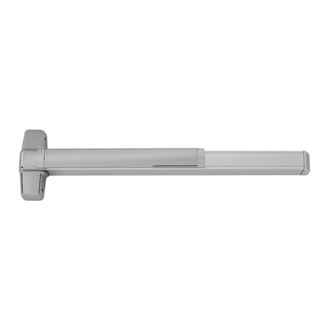
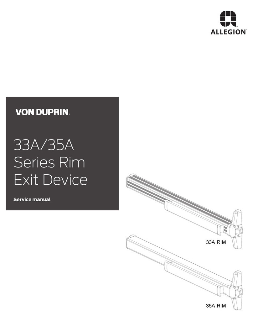
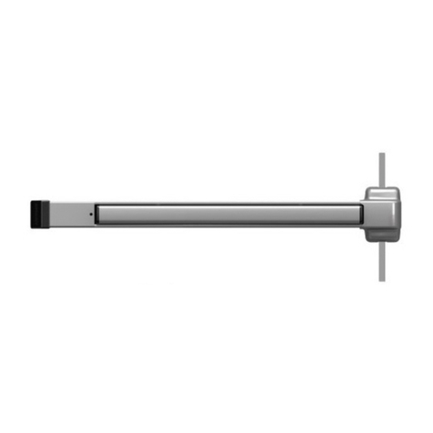
Von Duprin 33A Series User manual


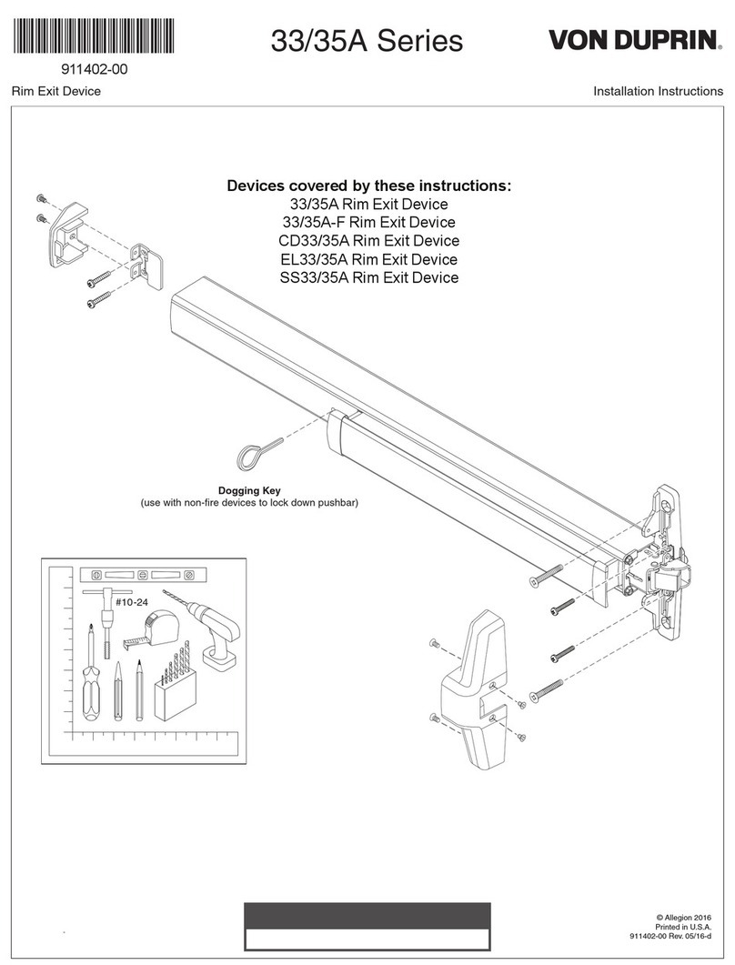
911402-00
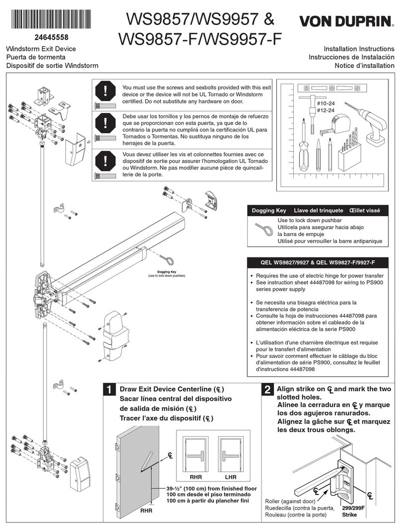
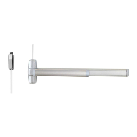
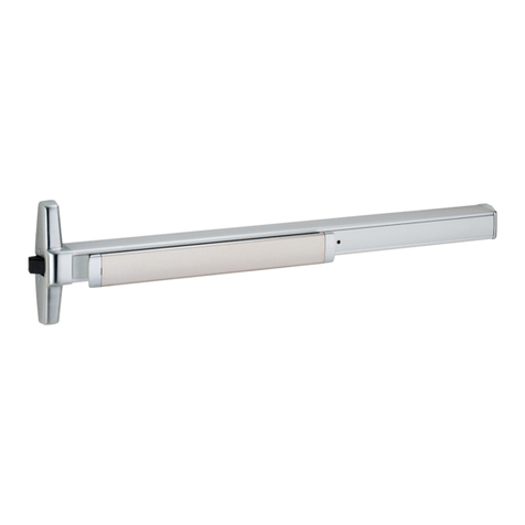
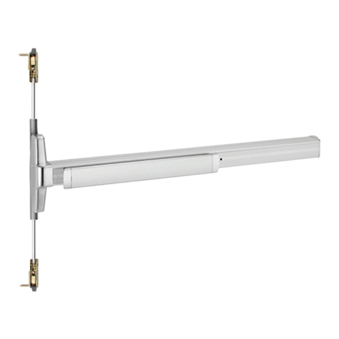
Rim Exit Device Installation Instructions
33/35A Series
Devices covered by these instructions:
33/35A Rim Exit Device
CD33/35A Rim Exit Device
EL33/35A Rim Exit Device
SS33/35A Rim Exit Device
Index:
Screwchart ............................2
Deviceinstallation................3-5
Optionalequipment.................6
Strike preparation ................7-8
Templates ........................... 9-10
Special tools needed:
5/64”hexwrench
#10-24 tap
Drillbits: #25,1/8”, 1/4”,
5/16”,13/32”
2
1/4-20x1”
1/4-20x1-1/2”
Trimmountorsexbolts:
(2-1/4”door)
(1-3/4”door)
SCREW CHART
#8-18x3/8”threadcutting Centercasecover
G
A
#10-16X3/8”Threadcutting End cap
#10-24X3/4”
#10X1-1/2”Woodscrew
Metalframe
Woodframe
#10-24X3/4”
#10-24X1-1/8”
C
Surface mountor
Sexbolts2-1/4”door(silver)
Sexbolts1-3/4”door(silver)
D
E#10-12x10-24x1-1/4”combination Metalorwoodframe
#10-12x10-24x1-1/4”combination Metalorwoodframe
F
H
B#10-24X1” Metaldoorsurfacemount
(Yellow)
#10X1-1/4” Wooddoorsurfacemount
3
Install strike using two
screws only at this time.
A. Center wear strip on strike as shown.
B. Mark and drill 1/8” dia. holes (4 places).
C. Installwear stripwith flat headdrive
rivets(4places) from1439 strike package.
1439 Strike (standard)
Wear
strip
299 Strike 1606 Strike
Mullion
Door
2
1
*Fordouble doors witha
mullionand strike already
installed, use existing
strike center line.
RHRshown
(LHR opposite)
Draw device center line ( )
on door and frame as shown.
C
L
4
3
Install strike
1/16”past door
side of stop
See pages 7 and 8 for strike templates
and frame preparation dimensions.
If using a 1439 strike, install
wear strip. If not, go to step 5.
Prepare frame for strike
using paper templates.
1439 strike
preparation
shown
E
F
G
*39-13/16”
tofinished
floor
Door
side
Door
C
L
4
5
Tape template to door and
mark door. Prepare lock side of door
for device and trim.
Seetemplatefordrilland
cut-outinformation
X
X
See trim instructions for
pullside doorpreparation.
Paper Template
(pages 9and 10)
Markvertical line X-X for trimalignment
Markdoor
cut-out
Mark 4
holes
Note: Line X-X is a reference line on the paper template used for
trim and exit device alignment. Line X-X shown here should
correspond to line X-X in the trim installation instructions
C
L
dengilaeciveD gnitnuomhtiw seloh
Cut device to length.
Measure to determine
length to cut device.
cutdevice
squareand
removeallburrs
Note:Device must
be cut square for
properend capfit
Tape
Coverplate
(flushto pushbar)
Pushbar
Anti-rattle clip
(removewhile cutting,then
replaceafter cutting)
Prepare device for cutting
Cut device square
If5/8” diameter wireaccess hole
hasbeen predrilled indoor,cut
device5/16” fromcenter ofhole.
”61
/5
Note
1-3/16” minimum clearance
(with end cap removed)
5
7
6
8
5
299/299F/1606 Strike
3/16”
Strike
plate #25 Drill
#10-24 tap
1/8” Drill pilot
1” deep
MetalWood
Adjust strike with shim (if
necessary) and secure strike.
1409 Strike
3/16”
299 - Add plate and middle screw
Shim strike for 3/16” clearance to chassis
Shim
(ifnecessary)
F
Shim
(ifnecessary)
Center
case cover
Removeprotectivefilm
frompushbar
Install 2 support screws,
center case cover, and end cap.
2support
screws
B
H
Center
case
Trim (optional)
OR
Install trim (if using) and secure
device center case to door. Install hinge stile
mounting bracket.
#325 Sex bolts
(requiredwhen
not using trim)
A
Secure mounting bracket
*Tailpiece
Tailpiece
guide
Cuttailpiece
ifneeded
1/8”
Door
surface
*Tailpiece is attached to
trimor cylinderdepending
onapplication
9
11
10
12
Rotate tailpiece
guide to match
tailpiece
Mounting
bracketflush
Leveldevice
Mark and prepare 2 mounting holes
Metal
Wood
1/4” drill
inside
13/32” drill
outside
13/32” drill
thru
End cap
D
C
#425
Sex bolts
(required)
6
OPTIONAL EQUIPMENT
1. Remove mortise cylinder cam and
reinstall in reverse (Figure 1).
2. Insert key and rotate cam to install
the cylinder to the cover plate (Figure 2).
3. Remove key to slide cover plate in
position in the mechanism case.
Std. mortise
cylinder
Mortise
cylinder
cam
Std. mortise
cylinder
Mortise
cylinder
cam
CD function conversion
Figure 1
Figure 2
Std. mortise
cylinder
Cylinder
collar
Dogging
platecover
Offsettoward
pushbar
Cylinder
locatingwasher Cylinder
lock nut
Mechanism
case
Turn cylinder key clockwise approx. 1/8
turnforstandard dogging
Dogging procedure
Depresspushbar
CD (CYLINDER DOGGING)
7
1439 Strike
FramePreparation
7/8”
7/16”
7/16”
1-9/16”to
faceof
door
Bladestop
7/8”
Cut-out
C
L
C
L
RHR shown
(LHRopposite)
1439Strike
#25Drill
#10-24tap
1/8” Drill pilot
1”deep
MetalWood
8
299 Strike
Template
Door
Stop
RHR
Cutpaperalong this line
and place on door stop
against edge of door
(seepicturebelow)
L
C
Template
LHR
5/8”
1-1/16”
L
C
1-1/16”
Door edge
#25Drill
#10-24tap
1/8” Drill pilot
1”deep
MetalWood
9
3/16”
1/4”
7/32”
7/8”
1-3/16”
3-1/8”
C
Lof device
33/35A Rim device
Template
LHR
C
Lof device
X
X
7/8”
1-3/16”
3-1/8”
7/8”
19/32”
1/4”
Radius
#25 drill inside
#10-24 tap
1/8”diameterdrill
1” deep pilot hole
Metal
Wood
Holes - 2 places
5/16” drill inside
13/32”drilloutside (sex bolts)
1/2”drilloutside (trim)
13/32”drill thru(sexbolts)
1/2”drill thru(trim)
Metal
Wood
Holes - 2 places
Cut-out
device side only
5/8” deep for
wood door
Align this line
with edge of
strike or roller
LineX-Xisareferencelinefor
trimandexitdevicealignment.
LineX-Xshownhereshould
correspondtolineX-Xinthe
trim installation instructions
10
33/35A Rim device
Template
RHR
3/16”
1/4”
7/32”
7/8”
1-3/16”
3-1/8”
C
L
Device
C
L
Device
Cut-out
device side only
5/8” deep for
wood door
7/8”
1-3/16”
3-1/8”
7/8”
19/32”
1/4”
Radius
#25 drill inside
#10-24 tap
1/8”diameterdrill
1” deep pilot hole
Metal
Wood
Holes - 2 places
X
X
5/16” drill inside
13/32”drilloutside (sex bolts)
1/2”drilloutside (trim)
13/32”drill thru(sexbolts)
1/2”drill thru(trim)
Metal
Wood
Holes - 2 places
Align this line
with edge of
strike or roller
LineX-Xisareferencelinefortrimand
exitdevicealignment.LineX-Xshown
hereshouldcorrespondtolineX-Xin
the trim installation instructions
11
This page
intentionally
left blank
12
© Allegion 2014
Printed in U.S.A.
911402-00 Rev. 01/14-c
Customer Service
1-877-671-7011 www.allegion.com

Other manuals for 33A Series

1

This manual suits for next models

10

Other Von Duprin Door Opening System manuals
Von Duprin Quiet One 9847WDC User manual

Von Duprin

Von Duprin Quiet One 9847WDC User manual

Von Duprin WS9927 User manual

Von Duprin

Von Duprin WS9927 User manual

Von Duprin WS9857-F User manual

Von Duprin

Von Duprin WS9857-F User manual

Von Duprin 33A Series User manual

Von Duprin

Von Duprin 33A Series User manual

Von Duprin Chexit CX33A/35A User manual

Von Duprin

Von Duprin Chexit CX33A/35A User manual

Von Duprin 35A-F User manual

Von Duprin

Von Duprin 35A-F User manual

Von Duprin QEL94/9547 Series User manual

Von Duprin

Von Duprin QEL94/9547 Series User manual

Von Duprin 33/3527A User manual

Von Duprin

Von Duprin 33/3527A User manual

Von Duprin 9849WDC User manual

Von Duprin

Von Duprin 9849WDC User manual
Von Duprin 33/35A User manual

Von Duprin

Von Duprin 33/35A User manual

Von Duprin XP98 User manual

Von Duprin

Von Duprin XP98 User manual

Von Duprin Allegion 3327A Series User manual

Von Duprin

Von Duprin Allegion 3327A Series User manual

Von Duprin 2227-F User manual

Von Duprin

Von Duprin 2227-F User manual

Von Duprin 98 User manual

Von Duprin

Von Duprin 98 User manual

Von Duprin 9950WDC User manual

Von Duprin

Von Duprin 9950WDC User manual
Von Duprin 98/9927 User manual

Von Duprin

Von Duprin 98/9927 User manual

Von Duprin 3550AWDC User manual

Von Duprin

Von Duprin 3550AWDC User manual
Von Duprin 98/9949 User manual

Von Duprin

Von Duprin 98/9949 User manual

Von Duprin 98/9975 Series User manual

Von Duprin

Von Duprin 98/9975 Series User manual

Popular Door Opening System manuals by other brands

Helm MK-L 80 G 120 installation instructions

Helm

Helm MK-L 80 G 120 installation instructions

Assa Abloy Yale 2500 Series installation instructions

Assa Abloy

Assa Abloy Yale 2500 Series installation instructions

Saxco RG-AT40S-I/O manual

Saxco

Saxco RG-AT40S-I/O manual

SUGATSUNE LAMP DC Series installation manual

SUGATSUNE

SUGATSUNE LAMP DC Series installation manual

Henderson HUSKY 100 Fitting instructions

Henderson

Henderson HUSKY 100 Fitting instructions

Dorma ES 68 user manual

Dorma

Dorma ES 68 user manual

fadini APROLI 380 LB instruction manual

fadini

fadini APROLI 380 LB instruction manual

Fireco Freedor SmartSound user guide

Fireco

Fireco Freedor SmartSound user guide

Sesamo Puma Millenium Installation instruction

Sesamo

Sesamo Puma Millenium Installation instruction

Pima 8841202 instruction manual

Pima

Pima 8841202 instruction manual

Assa Abloy Corbin Russwin DC8200 Series installation instructions

Assa Abloy

Assa Abloy Corbin Russwin DC8200 Series installation instructions

BLUM SERVO-DRIVE Instruction leaflet

BLUM

BLUM SERVO-DRIVE Instruction leaflet

Assa Abloy Corbin Russwin PED5400 FE installation instructions

Assa Abloy

Assa Abloy Corbin Russwin PED5400 FE installation instructions

ForceDoor FS 1000 Installation instructions and user guide

ForceDoor

ForceDoor FS 1000 Installation instructions and user guide

CAME A4364 manual

CAME

CAME A4364 manual

PDQ DOOR CLOSER instruction sheet

PDQ

PDQ DOOR CLOSER instruction sheet

Norton 1600 Series installation instructions

Norton

Norton 1600 Series installation instructions

Ribind VERTIGO 8 Assembly

Ribind

Ribind VERTIGO 8 Assembly

manuals.online logo
manuals.online logoBrands
  • About & Mission
  • Contact us
  • Privacy Policy
  • Terms and Conditions

Copyright 2025 Manuals.Online. All Rights Reserved.