manuals.online logo
Brands
  1. Home
  2. •
  3. Brands
  4. •
  5. Von Duprin
  6. •
  7. Lock
  8. •
  9. Von Duprin 371-L User manual

Von Duprin 371-L User manual

*941098-00*
941098-00
XX
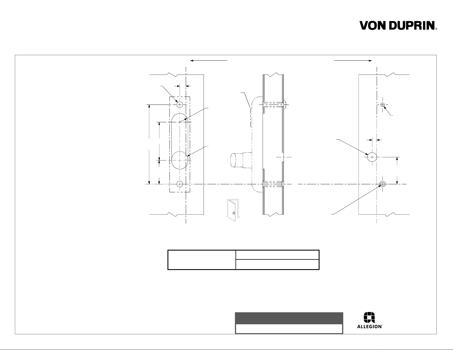
Line X-X corresponds to line X-X on exit device instructions
C
L
Corresponds to
center line of exit
device on exit
device instructions
11/16” R, 2 places
(omit for BE)
1/2” dia.
2 places
6-1/4”
Outside
face of
lock stile
Inside
face of
lock stile
LHR shown
RHR opposite
5/16” dia.
3”
1/2”
1-7/8”
3/4” dia.
thru one
wall
3/8”
2-1/8”
5/16” dia.
c’sink 1/2” dia x 82 degree
XX
1. Prepare door for exit device. Seeexit
device instructions for locations of
holes, backset (line X-X), and center
lines.
2. Prepare door for control:
A. Transfer line X-X from inside (exit
device side) of door to outside
(control side) of door. Use extra
care if edge of door is beveled.
Be sure line X-X is parallel to edge
of door.
B. Locate and prepare holes as
indicated.
3. Install rod member (Figure 1):
A. Slip top rod assembly in door until
bottom of rod is visible in control
cutout.
B. Slip rod member on top rod
according to handing of door. Keep
rod member visible in cutout and
lower top rod assembly until latch
release is in position on latch release
reinforcement. Slightly tighten socket
set screws in rod member to
maintain this position.
C. Complete the installation and
adjustment of top and bottom rod
assemblies. See directions for
vertical rod device.
4. Install cylinder if required (Figs. 2 &3).
Insure cylinder cam is set for required
function and replace if necessary.
5. Install control and adjust member so
that the bottom surface is against top
surface of control cam. Secure rod
member by tightening socket set
screws.
6. Apply device and test key, control,
and device action.
1-3/8” dia.
(BE only)
Omit cylinder
for BE function
For cutouts on inside face
of door see instructions in
device carton
Device Application Schedule
8847-F Vertical Rod Exit Device
Control
371-L & 371-L-BE
Installation Instructions
Customer Service
1-877-671-7011 www.allegion.com/us
© Allegion 2014
Printed in U.S.A.
941098-00 Rev. 01/14-b
Cylinder cam in
this position with
key removed
NL TL
TL Function - Control remains unlocked
when key is removed
NL Function - Control relocks when key is
removed. Requires use of key to operate
For NL function replace TL cylinder plate
(std. on all controls) with NL cylinder plate
(included in polybag) replacing screw and
washer.
Note: Control must be in locked position
when installing cylinder plate.
Mortise
cylinder
Cylinder locating
washer
Cylinder nut
Hexagon mounting
extension
Socket set
screw
Figure 2
Figure 3
Outside face
of door
Edge of
door
Install rod member
in this position for
LHR door
Install rod member
in this position for
RHR door
Figure 1

This manual suits for next models

1

Other Von Duprin Lock manuals

Von Duprin 7500 User manual

Von Duprin

Von Duprin 7500 User manual

Von Duprin 2227 Series User manual

Von Duprin

Von Duprin 2227 Series User manual

Von Duprin LGO User manual

Von Duprin

Von Duprin LGO User manual

Von Duprin 370L User manual

Von Duprin

Von Duprin 370L User manual

Von Duprin StrikeForce 6224 User manual

Von Duprin

Von Duprin StrikeForce 6224 User manual

Von Duprin 6211 User manual

Von Duprin

Von Duprin 6211 User manual

Von Duprin 388NL User manual

Von Duprin

Von Duprin 388NL User manual

Von Duprin StrikeForce 6210 User manual

Von Duprin

Von Duprin StrikeForce 6210 User manual

Von Duprin 9975 User manual

Von Duprin

Von Duprin 9975 User manual

Von Duprin StrikeForce 6211WF User manual

Von Duprin

Von Duprin StrikeForce 6211WF User manual

Popular Lock manuals by other brands

Salto Aelement installation guide

Salto

Salto Aelement installation guide

COMPX Stock Locks C2174-70-DC-KD Dimensional drawing

COMPX

COMPX Stock Locks C2174-70-DC-KD Dimensional drawing

Carrier LENEL S2 manual

Carrier

Carrier LENEL S2 manual

COMPX Chicago Tubar IC-12L instruction sheet

COMPX

COMPX Chicago Tubar IC-12L instruction sheet

Babypeta Stick'n'lock installation instructions

Babypeta

Babypeta Stick'n'lock installation instructions

Axim PR-7085P Series technical information

Axim

Axim PR-7085P Series technical information

Snap-loc E-TRACK SINGLES manual

Snap-loc

Snap-loc E-TRACK SINGLES manual

BELLEVUE ELB-45 Fittings guide

BELLEVUE

BELLEVUE ELB-45 Fittings guide

Burg Flexo.Code operating manual

Burg

Burg Flexo.Code operating manual

SilverCloud YR300 user manual

SilverCloud

SilverCloud YR300 user manual

Andersen 100 Series Application guide

Andersen

Andersen 100 Series Application guide

Relcross Door Controls Keylex K900 Installation & operation

Relcross Door Controls

Relcross Door Controls Keylex K900 Installation & operation

Assa Abloy Sargent ELR Series installation instructions

Assa Abloy

Assa Abloy Sargent ELR Series installation instructions

Assa Abloy Access Control Electric Locking Catalog

Assa Abloy

Assa Abloy Access Control Electric Locking Catalog

Command access MLRK1 Series Insert Instructions

Command access

Command access MLRK1 Series Insert Instructions

SECO-LARM SD-231-ND1Q user manual

SECO-LARM

SECO-LARM SD-231-ND1Q user manual

Schlage BE489WB reference guide

Schlage

Schlage BE489WB reference guide

Anviz L100K installation guide

Anviz

Anviz L100K installation guide

manuals.online logo
manuals.online logoBrands
  • About & Mission
  • Contact us
  • Privacy Policy
  • Terms and Conditions

Copyright 2025 Manuals.Online. All Rights Reserved.