10 933.HK18 1.18.198.12 2019 Hyundai Santa Fe
©2023 Directed. All rights
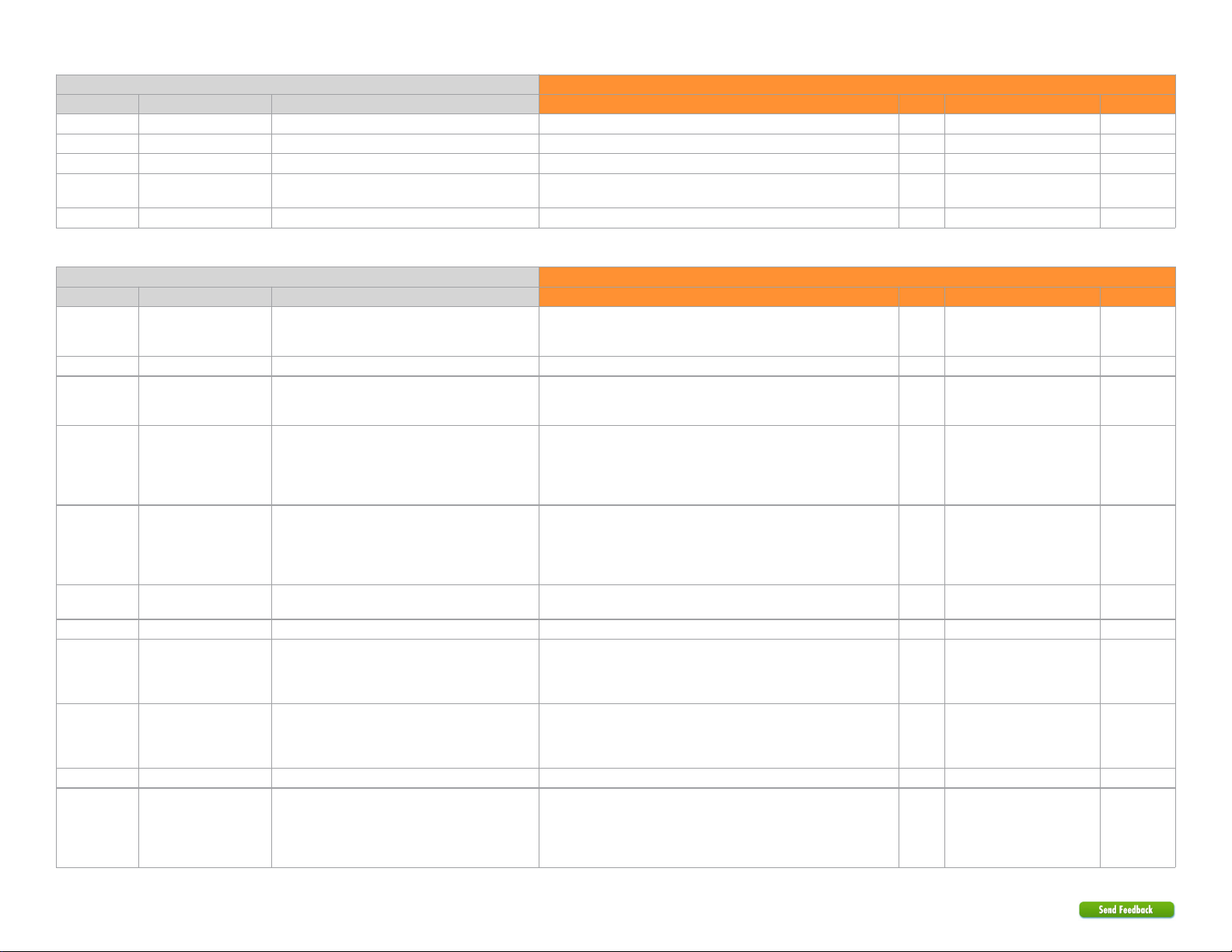
Module Connects To
Conn./Pin Color Description Wire Location (+/-) Wire Color Connection
H2/18 Orange/Black (+) Instant Trigger Input No Connection
H2/19 Blue (-) Trunk Trigger Input No Connection
H2/20 Green (-) Door Trigger Input No Connection
H2/21 Gray (-) Hood Switch Input [1] The installation of an aftermarket hood pin is ONLY required on vehicles
that are NOT equipped with a factory hood pin.
H2/22 Violet/White (AC) Tach Input No Connection
Main harness, 12-pin black connector (H3)
Module Connects To
Conn./Pin Color Description Wire Location (+/-) Wire Color Connection
H3/1 Blue/White Relay N.C. - Immo. Data Interrupt (vehicle side) [4] Driver Kick, red 54 pin plug (EM11), pin 40
The EMS COM connection is NOT required in US vehicles without
transponder.
Data White/Orange or Black Remote Start
Only
H3/2 Blue/Red Relay N.O. - No Connection No Connection
H3/3 Blue Relay COM. - Immo. Data Interrupt (connector side)
[4]
Driver Kick, red 54 pin plug (EM11), pin 40
The EMS COM connection is NOT required in US vehicles without
transponder.
Data White/Orange or Black Remote Start
Only
H3/4 White/Brown Relay N.C. - Ignition Interrupt (vehicle side) [5] ICU Junction Block-Dash Fuse Box, rear, white 47 pin plug (G), pin 1
Do not insert 15A fuse
The connection is only required to maintain OEM remote functionality
during remote start. The TPMS light will come ON during runtime or idle
mode and will go out after vehicle takeover.
Cut Gray/Orange Remote Start
Only
H3/5 White Relay COM. - Ignition Interrupt (connector side) [5] ICU Junction Block-Dash Fuse Box, rear, white 47 pin plug (G), pin 1
Do not insert 15A fuse
The connection is only required to maintain OEM remote functionality
during remote start. The TPMS light will come ON during runtime or idle
mode and will go out after vehicle takeover.
Cut Gray/Orange Remote Start
Only
H3/6 Red (+) 12 Volt Input Ignition Switch, black 6 pin plug, pins 1 and 5 + Blue/Orange and White
(15A)
Mandatory
H3/7 Lt. Green/Red Relay N.O. - No Connection No Connection
H3/8 Lt. Green Relay COM - Accessory Interrupt (connector side)
[5]
ICU Junction Block-Dash Fuse Box, rear, white 47 pin plug (G), pin 45
The connection is only required to maintain OEM remote functionality
during remote start. The TPMS light will come ON during runtime or idle
mode and will go out after vehicle takeover.
Cut Pink Remote Start
Only
H3/9 Lt. Green/White Relay N.C. - Accessory Interrupt (vehicle side) [5] ICU Junction Block-Dash Fuse Box, rear, white 47 pin plug (G), pin 45
The connection is only required to maintain OEM remote functionality
during remote start. The TPMS light will come ON during runtime or idle
mode and will go out after vehicle takeover.
Cut Pink Remote Start
Only
H3/10 Black (-) Ground (chassis ground) Mandatory
H3/11 White Relay COM. - Ignition Interrupt (connector side) [5] ICU Junction Block-Dash Fuse Box, rear, white 47 pin plug (G), pin 1
Do not insert 15A fuse
The connection is only required to maintain OEM remote functionality
during remote start. The TPMS light will come ON during runtime or idle
mode and will go out after vehicle takeover.
Cut Gray/Orange