OSVWT20A-EN
9/12
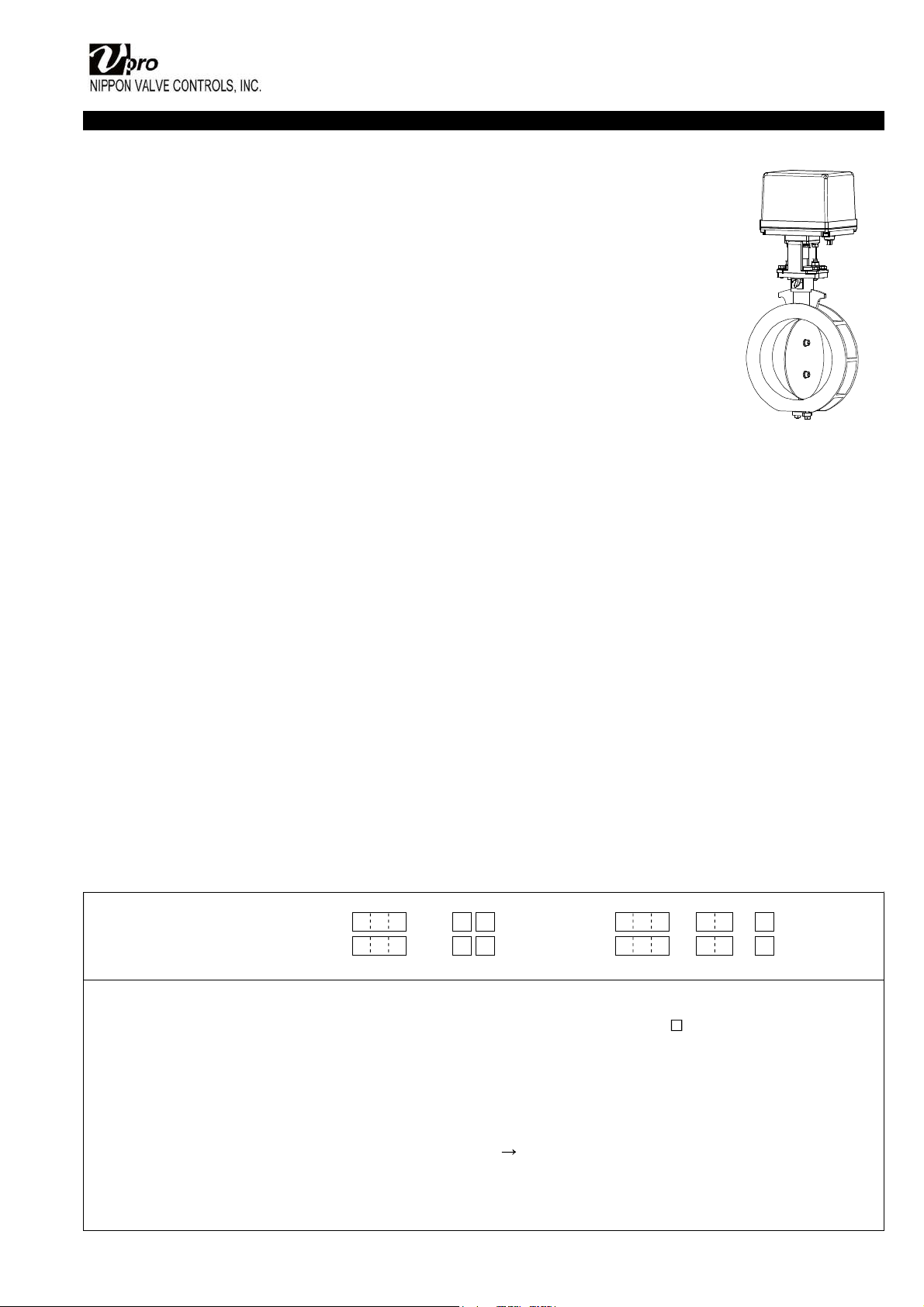
INSTALLATION, OPERATION & MAINTENANCE INSTRUCTIONS
HANDLING & STORAGE
HANDLING
Proper care in handling the damper should be taken
to prevent damage. Do not drop or throw it.
STORAGE
Store the actuator in the protected area from dust,
moisture, and direct sunlight. If possible, should be
kept in the original packaging.
CHECKING
• Check the product code, power supply, and voltage
before installation.
• Make sure that the bolts are not loose.
• DIP switch be sure perform set up before a power
supply injection.
Should not change an unnecessary switch.
INSTALLATION
PRECAUTIONS
• Before installing, clean pipe and damper ends.
Make sure they are free of dirt, dust and etc.
• The butterfly damper should be piped upstream of
the elbow. When piping downstream from the elbow,
considered a straight line that is at least five times the
length of the pipe.
• The damper stem should be mounted perpendicular
to the flow for biased fluid.
• Disc interference may also occur when damper is
installed in pipeline with smaller than normal inside
diameter such as thick wall pipe, or lining pipe.
Suitable corrective measurement must be taken
(taper boring the pipe or pipe liner, etc.)
PIPING FLANGES
• It has a flow direction. Install the damper accordingly.
• Gasket should be selected appropriately to suit the
fluid, pressure and temperature.
Use spring washer to prevent from decreasing surface
pressure gasket when the temperature change
happens frequently.
• Wafer type ball damper is put between two seats of
flanged-end and tightened with long bolts.
• Center the damper to the flanges accurately.
• After installation of the damper, operate the damper to
make sure the disk does not touch any part of the
piping.
• Tighten all bolts using crossover method to load the
joint evenly.
ENVIRONMENT
• Do not install in place where corrosive gas is present
or where vibration is heavy (0.5 G or more).
• When radiant heat causes the surface temperature of
the control unit to exceed 55°C, provide an
appropriate shielding plate.
• If there is a possibility that the fluid and drive part
freeze, please take measures to prevent freezing.
POSITIONING
Should be positioned through 90° upward from
horizontal. Provide space around the product to allow
manual operation, inspection and replacement work.
Maintenance space for upper part of actuator.
AEX PEX More than 105 mm
AEX (02K / 06K) More than 120 mm
CAUTION AFTER PIPING
Until the wiring is completed there must be no
condensation or flooding in the interior of the actuator,
after piping. Protective caps on the cable gland are
not waterproof.
INSULATION WORK
• For maintenance of gland packing, insulation should
be below the ground part.
• The upper part of the ground plate part is a heat
dissipation part, do not insulate it.
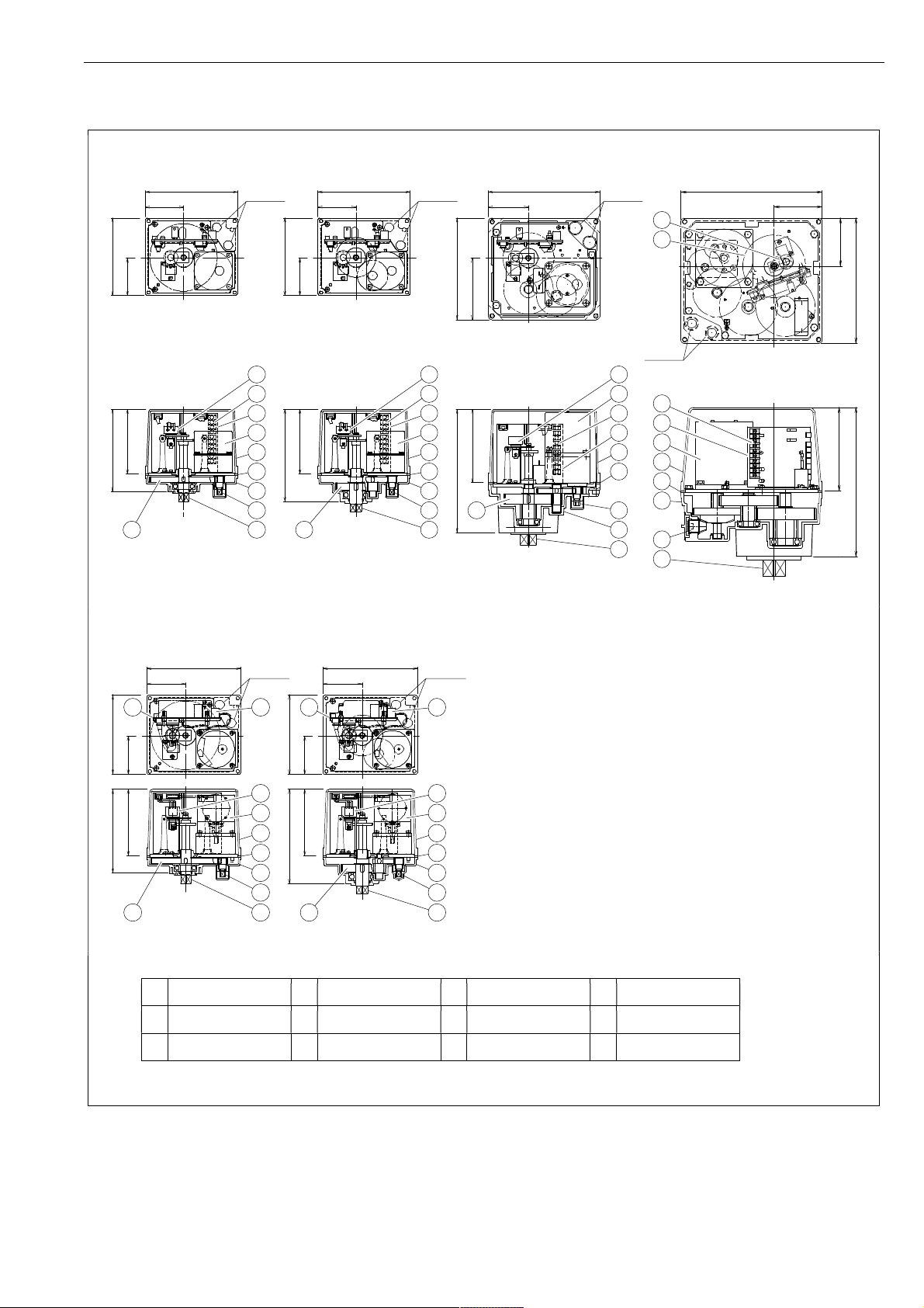
TIGHTEN THE GLAND NUTS
• Check that there is no leakage from the gland
packing.
• If it leakage, tighten gland nuts by alternately.
Do not over-tighten the gland nuts.
Recommended torques [Nm]
Size [mm] Torque
040 to 065 1
080 to 125 2
150 to 300 5
350 to 400 8
Slow Fast Slow Fast
Gland nut
Gland plate
Stem