10
HAGAB – INSTALLATION, OPERATION AND MAINTENANCE
INTACT
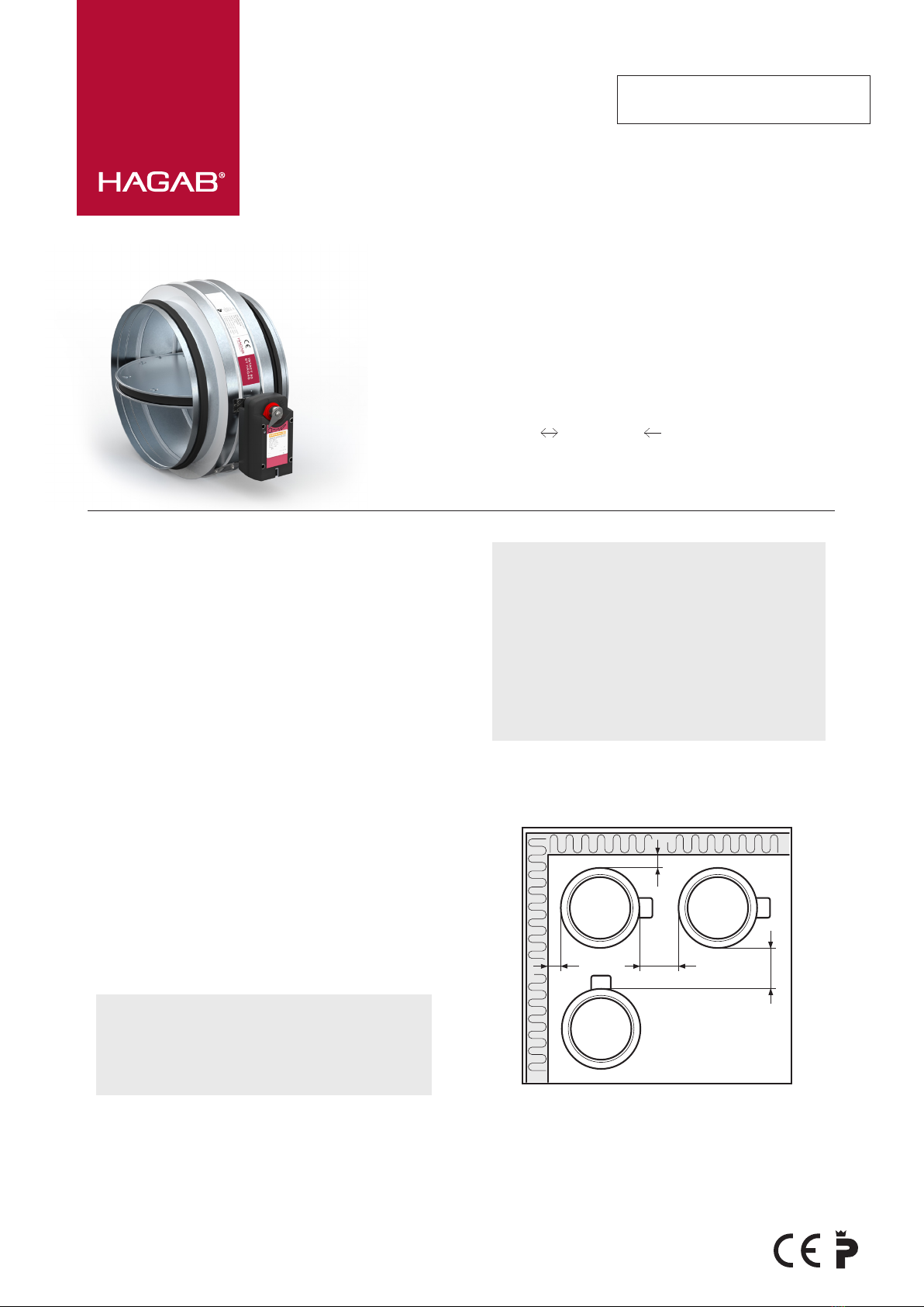
Fire/Fire gas damper
There is a handle on the engines for dimension 100-315
mm. The handle shall be in position 1, with exception for
when the control require position 2.
1. (0)2-10 VDC
2. 2-10 VDC
3. Do not use, hinders rotation of the blade
4. Do not use, hinders rotation of the blade
CONTROL
The fire gas damper must be function tested at least once
every 48 hours. The function test means that the dampers
must close and open at intervals as above.
The function test must be performed automatically and can
be controlled by e.g. a control and monitoring system.
05 2022
Hagab Box 135, 562 02 Taberg
|
Visit Industrivägen 5, 562 41 Taberg
|
Phone 036-36 30 90
|
Fax 036-36 30 99
|
www.hagab.com
|
Sales Office Jönköping Phone 036-36 30 90
|
Stockholm Phone 08-689 90 10
21
L1N
M
S2S1
<5˚ <80˚
S5S4 S6S3
-+
~AC 24 V
DC 24 V
AC 230 V
21 S2S1
<5˚ <80˚
S5S4 S6S3
3 4
U
Y
-
+
~
DC (0)2...10 V
DC 2...10 V
TF1 TF2
LED
Test
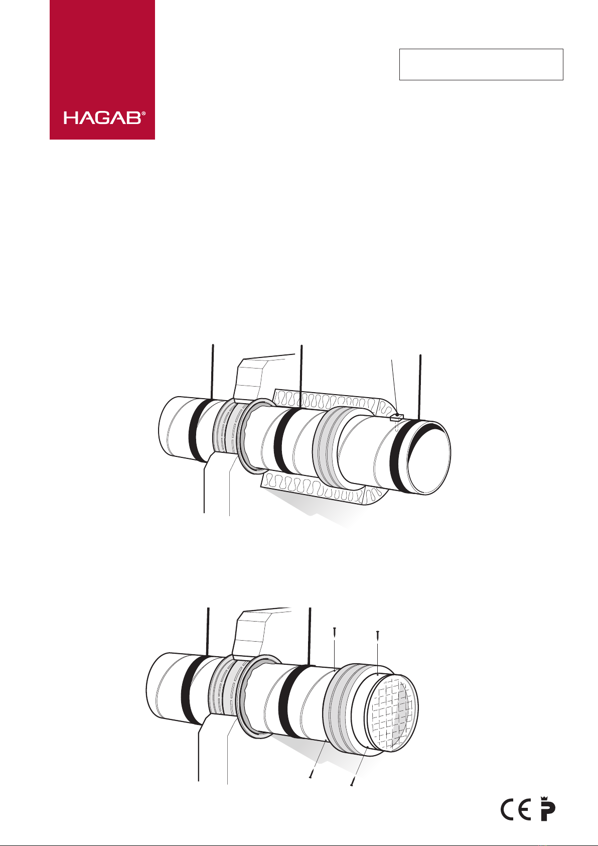
OPERATING AND MAINTENANCE
INSTRUCTIONS
Periodic inspection once per year.
INTERNAL CONTROL VIA INSPECTION COVER
OR CLEANING HATCH IN CONNECTING DUCT
– Check by triggering the smoke detector so the damper
closes.
– Check that the damper blade closes and opens freely by
switching off power to the actuator. If the junction box
KBHA-1 is installed, press the “DAMPER TEST” button.
Keep the button pressed to interrupt the voltage to the
actuator. Alternatively, the voltage can be interrupted by
pressing the “Test” button on the damper’s thermal sensor.
– Check the fitting of the sealing strip on the damper blade.
– Check the cleaning requirements in conjunction with the
ventilation system function test.
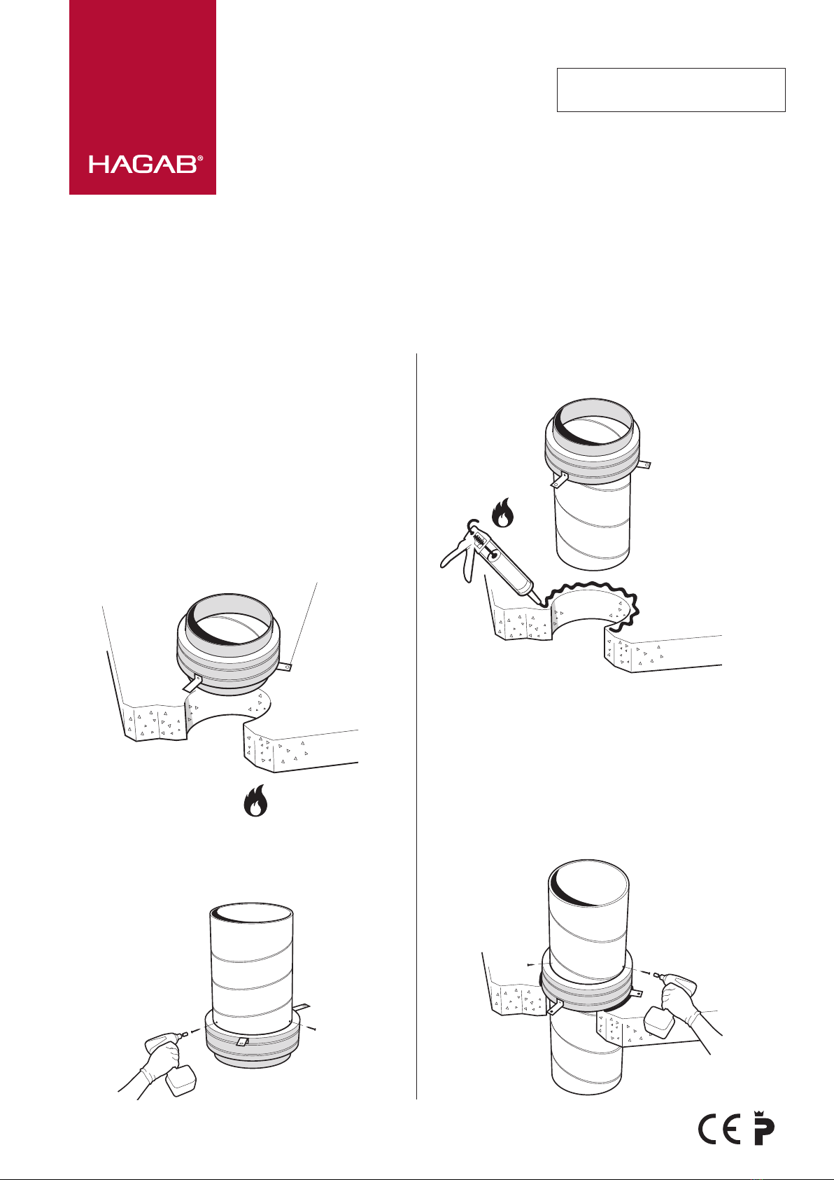
EXTERNAL CONTROL
– Check that the damper frame has not been
subjected to mechanical damage.
– Check that the seal in the structural element has
not been damaged.
– Check the fitting of the actuator on the shaft and frame.
– Check that the actuator cabling is not damaged.
– Check that the damper is clean. If necessary, wipe with
a slightly dampened cloth.
CLEANING
– When cleaning the inside of the damper, always choose
a gentle cleaning method such as a nylon brush and/or
compressed air.
SPARE PARTS LIST
See rating plate on the actuator.
WIRING DIAGRAM
HANDLE
WIRING DIAGRAM (ADJUSTABLE)
Drawing name: