manuals.online logo
Brands
  1. Home
  2. •
  3. Brands
  4. •
  5. VPro
  6. •
  7. Fire And Smoke Damper
  8. •
  9. VPro MA Series User manual

VPro MA Series User manual

OSYWT206-EN
1/4
Instruction manual
MA
-
SERIES
Butterfly Damper
WT
SP-1362
Please read this manual before installation and use.
GENERAL
Damper body and disk made by precision processing ensure
reduced leakage from damper seat.
This series can be used at fluid temperatures ranging from
-40 °C to 550 °C.
Manual operation
Lever
Gear
Damper
WT : For Wafer (JIS 5K)
PRODUCT CODE
WT type (Without seat) M A - W T - 2 T G 0 - -
(With SUS316 seat) M A - W T - 2 T G S - -
(1) (2) (3) (4) (5) (6) (7) (8) (9) (10)
(1) Actuator
MA-
(2) Damper
WT
(3) Manual operation
L : Lever
G : Gear
(4) Sizing code
- : Hyphen
(5) Connection
2 : JIS 5K
(6) Body material
T : SCS13A
(7) Packing material
G : Expansion graphite
(8) Seat material
0 : (Zero) None
S : SUS316
(9) Size [mm]
ex. 80 A 080
(10) Option
XM : Heat insulation
OSYWT206-EN
2/4
DAMPER SPECIFICATIONS
Water Oil Air, Gas Steam Chemicals Sea water Slurry Negative pressure
Damper type WT (Without seat) WT (With SUS316 seat)
Design 2-way, Wafer 2-way, Wafer
Connection JIS Flanges 5K JIS Flanges 5K
Fluid
Max pressure 20 kPa 20 kPa
Size [mm] 040 to 250 300 to 400 040 to 400
Material Body SCS13A SCS13A
Disk SUS420J2 SUS420J1 SUS410S / SUS420J2
Seat None SUS316
Stem seal Packing Expansion graphite Expansion graphite
PRESSURE & TEMPERATURE RATING
Temperature range : -40 to 600 °C
Option XM: High ambient temperature
more than +250 °C or less than -20 °C.
SEAT LEAKAGE VOLUME
Size [mm] Remarks
WT-2TG0 (Without seat) 040 to 050 Less than 2 % of rated Cv.
065 to 400 Less than 1 % of rated Cv.
WT-2TGS (With SUS316 seat) 040 Less than 1 % of rated Cv.
050 Less than 0.5 % of rated Cv.
065 Less than 0.2 % of rated Cv.
080 to 400 Less than 0.1 % of rated Cv.
INHERENT FLOW CHARACTERISTIC
Cv value (%)
D
amper
opening (%)
Range ability 50:1
Max
OSYWT206-EN
3/4
INSTALLATION, OPERATION & MAINTENANCE INSTRUCTIONS
HANDLING OF MANUAL LEVER
• The lever handle is removed and shipped.
• The lever mounting direction can be changed in units
of 45 degrees.
• Do not apply excessive torque to the lever.
• Do not strike or extend the lever with a tool.
Manual lever
Damper size [mm] Lever [mm] Hex bolt
L H A
040 to 125 115 36 9 M5×15
150 to 250 145 46 11 M5×15
300 220 52 14 M6×15
350 to 400 320 55 17 M8×15
HANDLING OF MANUAL GEAR
• Insert the handle into the gear shaft.
• Insert a pin into the hole in the handle.
Damper size [mm] K Actuator
080 to 400 150 MAG-F07
Butterflynut
BoltLever
Valvestem
OPEN/SHUT
indicator
L
H
A
φK
OPEN SHUT
Handle
Pin
OSYWT206-EN
Document is subject to change without notice.
NIPPON VALVE CONTROLS, INC.
1-21-19 Meieki minami, Nakamura-ku, Nagoya 450-0003 JAPAN
TEL: 81-52-582-6435 FAX: 81-52-582-6439
4/4
INSTALLATION, OPERATION & MAINTENANCE INSTRUCTIONS
HANDLING & STORAGE
HANDLING
Proper care in handling the damper should be taken
to prevent damage. Do not drop or throw it.
STORAGE
Store the damper in the protected area from dust,
moisture, and direct sunlight. If possible, should be
kept in the original packaging.
CHECKING
• Check the product code before installation.
• Confirm that there is no screw loose or part
deformation.
HANDLING OF MANUAL OPERATION
• Be careful about temperature of a lever / handle part,
when using it for the fluid of the high temperature or
low.
• Avoid the operation with bare hands, and make a
protective measure.
• For manual operation, loosen the butterfly nut before
operating. After operation, tighten the butterfly nut to
secure the position.
INSTALLATION
PRECAUTIONS
Before installing, clean pipe and damper ends.
Make sure they are free of dirt, dust and etc.
PIPING FLANGES
• It has a flow direction. Install the damper accordingly.
• Gasket should be selected appropriately to suit the
fluid, pressure and temperature.
Use spring washer to prevent from decreasing surface
pressure gasket when the temperature change
happens frequently.
• Wafer type ball damper is put between two seats of
flanged-end and tightened with long bolts.
• Center the damper to the flanges accurately.
• After installation of the damper, operate the damper to
make sure the disk does not touch any part of the
piping.
• Tighten all bolts using crossover method to load the
joint evenly.
• If a plastic flange used, do not over-tighten the bolts,
as this may deform the flange and cause leakage.
ENVIRONMENT
If there is a possibility that the fluid and drive part
freeze, please take measures to prevent freezing.
POSITIONING
Should be positioned through 90° upward from
horizontal. Provide space around the product to allow
manual operation, inspection and replacement work.
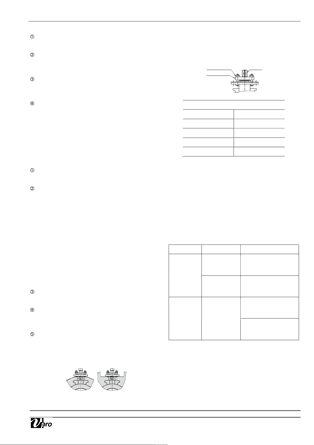
INSULATION WORK
• For maintenance of gland packing, insulation should
be below the ground part.
• The upper part of the ground plate part is a heat
dissipation part, do not insulate it.
TIGHTEN THE GLAND NUTS
• Check that there is no leakage from the gland
packing.
• If it leakage, tighten gland nuts by alternately.
Do not over-tighten the gland nuts.
Recommended torques [Nm]
Damper size [mm] Torque
040 to 065 1
080 to 125 2
150 to 300 5
350 to 400 8
MAINTENANCE
Do the routine maintenance at least once in half a
year.
Inspection items
• Confirm operation of opening and closing.
• Confirm whether screws are loose or not.
• Confirm the fluid temperature or pressure.
• Confirm the leak from damper stem.
• Confirm the bolt tightening torque.
TROUBLESHOOTING
Problem Cause Solution
Stop in the
mid position.
There is a
foreign object
in the damper.
Remove a foreign
object.
Damper is
distorted.
Replace the damper.
Leakage
from damper
gland
Gland packing
is worn or
distorted.
Tighten the gland nut.
Replace the gland
packing.
For more information contact
NIPPON VALVE CONTROLS, INC. for consultation.
Gland nut
Gland plate
Stem

Other VPro Fire And Smoke Damper manuals

VPro WT User manual

VPro

VPro WT User manual

VPro WT User manual

VPro

VPro WT User manual

VPro MA Series User manual

VPro

VPro MA Series User manual

VPro WT Series User manual

VPro

VPro WT Series User manual

Popular Fire And Smoke Damper manuals by other brands

Greenheck HPR Series Installation, operation and maintenance manual

Greenheck

Greenheck HPR Series Installation, operation and maintenance manual

Schako BSK-RPR Installation, mounting and operating instructions

Schako

Schako BSK-RPR Installation, mounting and operating instructions

Arzel RegiDamper installation instructions

Arzel

Arzel RegiDamper installation instructions

SagiCofim HTE 400 Assembly, installation and maintenance manual

SagiCofim

SagiCofim HTE 400 Assembly, installation and maintenance manual

klimaoprema FDC25 Series manual

klimaoprema

klimaoprema FDC25 Series manual

Greenheck EHM-601 Installation, operation and maintenance manual

Greenheck

Greenheck EHM-601 Installation, operation and maintenance manual

Schako BSK-RPR Additional operating instructions

Schako

Schako BSK-RPR Additional operating instructions

Mandik RKM Instructions for use

Mandik

Mandik RKM Instructions for use

mercor mcr WIP Series Operation and maintenance manual

mercor

mercor mcr WIP Series Operation and maintenance manual

Mandik FDMC Series instruction manual

Mandik

Mandik FDMC Series instruction manual

Wildeboer FR90 manual

Wildeboer

Wildeboer FR90 manual

Mandik FDMA-PM manual

Mandik

Mandik FDMA-PM manual

Trox Technik FK2-EU Installation and operating manual

Trox Technik

Trox Technik FK2-EU Installation and operating manual

LAJAC AUDA manual

LAJAC

LAJAC AUDA manual

Trox Technik FK2-EU installation manual

Trox Technik

Trox Technik FK2-EU installation manual

Wildeboer FK90 quick start guide

Wildeboer

Wildeboer FK90 quick start guide

SOLID AIR FDC25 manual

SOLID AIR

SOLID AIR FDC25 manual

SMAY CDH-F Operation and maintenance manual

SMAY

SMAY CDH-F Operation and maintenance manual

manuals.online logo
manuals.online logoBrands
  • About & Mission
  • Contact us
  • Privacy Policy
  • Terms and Conditions

Copyright 2025 Manuals.Online. All Rights Reserved.