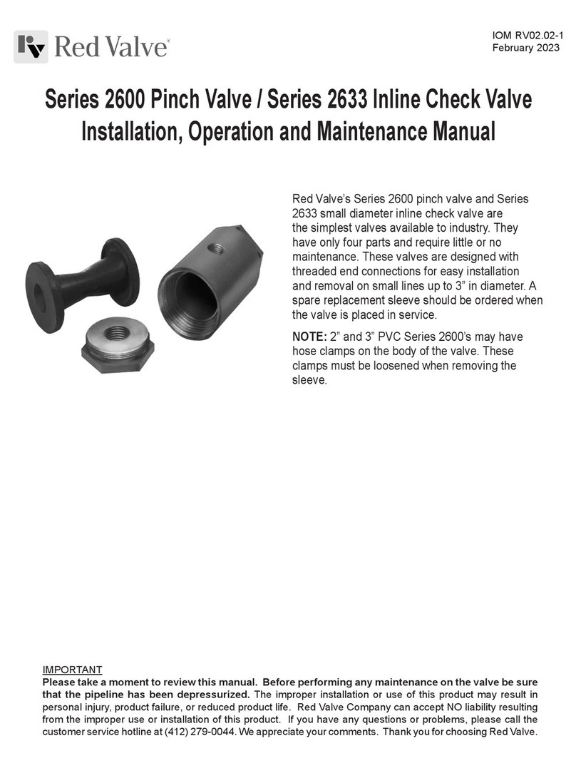
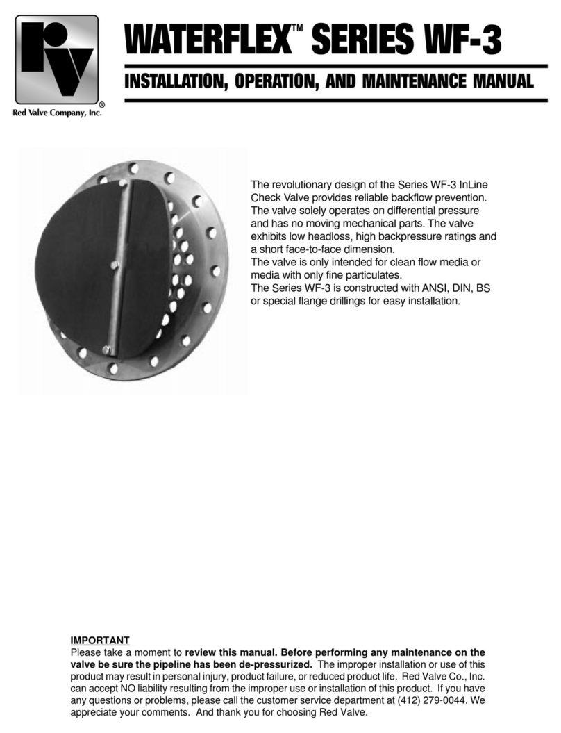
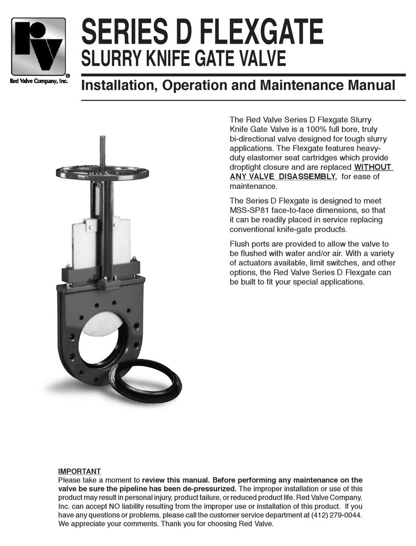
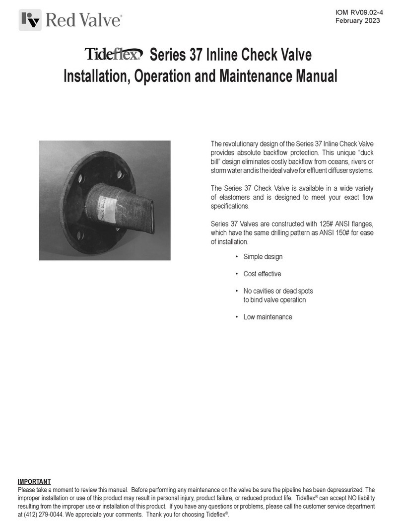
Red Valve G Series User manual

IMPORTANT
Please take a moment to review this manual. Before performing any maintenance on the
valve be sure the pipeline has been de-pressurized. The improper installation or use of this
productmayresultinpersonalinjury,productfailure,orreducedproductlife. RedValveCo.,Inc.
can accept NO liability resulting from the improper use or installation of this product. If you have
any questions or problems, please call the customer service department at (412) 279-0044. We
appreciate your comments. And thank you for choosing Red Valve.
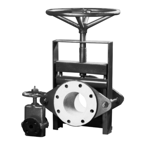
The Red Valve Series G Knife Gate Valve
is a 100% full bore, all-metal knife gate
valve designed for the toughest applications.
The Series G features heavy-duty cast-iron
body, stainless-steel wetted parts, and either a
metal or resilient seat.
The Series G is designed to meet MSS-SP81
face-to-face dimensions, so that it can be readily
placed in service replacing inferior knife gates.
Series G Knife Gate
Metal and Resilient Seated
Installation,Operation,andMaintenanceManual

The Series G Knife Gate Valve has A.N.S.I. B16.5 Class 125/150 flange
bolting dimensions, and a 150 psi cold working pressure rating. During
installation, great care must be taken to install the gate valve in the
proper direction. The gate must be installed so that the gate is pushed
against the seat by the flow pressure.
1. Remove the flange covers from the valve.
2. Check the flange faces of the pipe and valve for rough spots and
dents. Remove any damaged areas with fine sandpaper or file.
3. Check the valve for proper operation and any damage to the gate or
seat. Repair any damaged areas.
4. Clean the gasket surfaces of both the valve and the mating pipe
flanges.
5. IMPORTANT: Install the valve so that the gate is pushed against
the seat by the flow pressure. The seat must be placed on the
downstream or low pressure side of the gate. The word "SEAT" or "S"
is cast into the body, showing the position of the seat.
NOTE: Great care must be taken to properly install the valve, if the
valve is installed backwards the line pressure will push the gate away
from the seat, causing the valve to leak.
6. When installing the valve, be sure that the faces of the pipe flanges
are parallel to the raised faces of the valve. If the flanges are not parallel
the face gaskets may leak. 7. Install the face gaskets between the
flanges. Be sure that the inside diameter of the face gasket has the same
or slightly larger inside diameter than the raised face for the valve.
8. Install the flange bolts. Stud bolts should be installed in the chest area
of the valve. Be sure that the bolts are the proper length.
NOTE: Be sure that the bolts do not bottom out on the liner. If the
bolts bottom out on the liner, they may damage the pressure containing
part of the valve.
9. Tighten the flange bolts. Tighten the bolts to the recommended
torque and tighten all of the bolts evenly. NOTE: If the flange bolting is
not tightened evenly the valve may be damaged.
10. Apply grease to both the stem and grease nipple. Operate the valve
open and close, repeat the application of grease. Repeat this every three
months or as necessary.
11. IMPORTANT Tighten the packing bolts before applying pressure
to the valve. Packing bolts are loosened to increase the life of the
packing during storage.
ACTUATORS All actuators are furnished completely assembled and
fully operational. All valves with positioners and limit switches or
other instruments are properly set at the Red Valve factory.
HANDWHEEL The standard Series GSR has a left hand stem thread.
This allows the valve to close when the handwheel is turned in the
clockwise direction. The handwheel is labeled O-S (open and shut). The
handwheel is turned in either direction until the gate stops moving or is
fully seated.
BEVEL GEAR Bevel gears operate the same as the standard handwheel.
The handwheel is turned clockwise to close and counter clockwise to
open.
CHAINWHEEL Chainwheels can be furnished on both standard valves
and valves with bevel gears. The chain must be fed through the guides
and over the spokes around the outside diameter of the rim. The ends of
the chain are then connected with a connecting link.
CYLINDER ACTUATORS Cylinder actuated valves require a 50 psi
air supply to operate the standard cylinder. Actuators may be sized for
higher or lower plant air supply. A four-way valve must be used to
operate a standard cylinder. The open air supply is connected to the
lower cylinder head and close air source is attached to the upper
cylinder head. The valve must be assembled so that one side of the
piston is exposed to plant air, the other side of the piston must be
vented. If the valve has a fail safe system, air only needs to be supplied
to the open connection for fail close systems and the close connection
for fail open valves. The spring side of the piston should be vented.
If a pneumatic positioner is used, a 3 to 15 psi instrument signal is used
to control the positioner. Other pressure ranges of instrument signals
are available. Unless otherwise specified, the positioner will close the
valve upon increase of signal pressure.
Electronic positioners require a 4 to 20 mA control signal to position
the valve. As with pneumatic positioners, other control signals may be
provided and the standard positioner closes on increase of the
instrument signal.
ELECTRIC ACTUATORS Electric Actuators come completely
operational, with limit and torque switches set. Please refer to the
individual actuator manuals for additional operation or maintenance
information.
INSTALLATION OPERATION

RESILIENT SEAT REPLACEMENT
1. Make sure there is no pressure on the valve.
2. Remove the valve from the pipeline.
3. Close the valve so that the metal retaining ring is pushed away from
the body.
4. Insert a standard screwdriver between the body and metal retaining
ring. Do not insert the screwdriver too deeply or it may damage the
gasket. Gently twist the screwdriver several times around the
circumference of the seal retainer ring. NOTE: Be sure to remove the
retaining ring evenly.
5. Remove the two alignment pins. Remove the seat and the gasket.
6. Remove any rough spots with a fine file or sand paper. Only remove
enough metal to smooth the surface. Clean the metal retaining ring.
Make sure that the faces of the valve and seal retainer are clean and free
of scratches and dents.
7. Replace the seat ring and gasket it necessary. Use silicon seal to keep
gasket in place.
8. Open the valve.
9. Insert the retainer ring assembly. NOTE: Be sure that the alignment
pins are installed and the retainer ring is installed evenly.
10. Install the valve and new flange gaskets per the Installation Section.
NOTE: Be sure that the valve is installed in the proper direction, with
the seat on the low pressure side of the valve.
CYLINDER MAINTENANCE
The air used to operate the pneumatic cylinders, should be free of water
and other debris; it is not necessary to lubricate the air, but an air filter
is recommended. If water and other debris are in the air supply, cylinder
life may be shortened.
1. Check the piston rod for scratches and damage. Repair any minor
damage with a fine sandpaper or file. Only remove enough metal to
smooth the damaged area.
2. Make sure that there is no pressure in the valve.
3. Close the valve and remove air pressure from the cylinder. For valves
with fail open cylinders, closing pressure must be maintained on the
cylinder. Remove the bolts that connect the piston rod to the gate.
Operate the cylinder to the open position. For valves with fail close
cylinders, remove the cylinder assembly from the yoke.
PISTON ROD SEAL REPLACEMENT
4. Remove the adapter plate on the end of the piston rod.
5. Remove the four (4) bolts that connect the bronze seal retainer to the
lower cylinder head. Remove the bronze seal retainer.
6. Apply approximately 3 to 5 psi to the open side of the cylinder.
This should push the piston rod seal down the piston rod. Remove the
piston rod seal from the piston rod.
7. Replace the piston rod seal. Be careful not to damage the seal during
installation. Inspect the wiper ring in the seal retainer and replace it if
necessary. Reinstall the seal retainer and tighten the four bolts evenly.
PISTON SEAL AND CYLINDER GASKET REPLACEMENT
8. Cylinders with failsafe systems may remain bolted to the valve body.
Remove the four upper cylinder head nuts.
CAUTION: Make sure there is no pressure on the cylinder. If the
system has a spring loaded fail safe system, remove the top
cylinder head nuts evenly. If the nuts are not removed evenly, the
tie rod studs may be bent or broken, possibly causing Injury.
9. Remove the upper cylinder head. Remove the spring if the cylinder
has a fail safe option. Remove the cylinder from over the piston.
10. Clean the inside of the cylinder of any scale or buildup that has
developed. If the cylinder walls are scratched, use a very fine sandpaper
to remove the scratch or debris.
11. Clean both cylinder gasket grooves and replace the gaskets if
necessary.
12. Remove the nut that retains the piston to the piston rod. Remove
the upper piston stop and piston head and small o-rings.
13. Replace the first small o-ring that seals the piston rod and piston
head. Install the piston head and second small o-ring. Install the upper
piston stop and retainer nut. Tighten the retainer nut, use the hole in the
piston rod to keep the piston rod from turning. NOTE: Do not use a
pipe wrench or chain wrench on the piston rod.
14. Remove the o-ring on the piston head with a blunt instrument. Be
very careful not to scratch the outer edge of the o-ring groove or piston
O.D. If the areas are damaged, remove any scratches of damaged areas
with a fine file or sandpaper.
15. Lubricate the piston o-ring. cylinder gaskets and inside of the
cylinder. Use only compatable lubricants. Install the cylinder over
piston head. NOTE: Install the spring if the valve has a fail safe system.
Install the upper cylinder head, tighten the cylinder head nuts evenly.
16. Attach the adapter plate to the end of the piston rod. Slowly close
the piston, be sure that the groove in the adapter plate lines up with the
gate. Install the bolts that connect the gate to the piston rod.
17. Operate the valve open and close several times and check that all
nuts and bolts are tight.

INSPECTION Valves should occasionally be inspected for damage and
wear. The inspection period should be determined by the severity of
the service and environment. If valves are periodically inspected and
preventative maintenance done, the valve will last longer and operate
better.
CAUTION: Do not remove any valve parts or bolting with pressure in
the valve. It is very easy to inspect the valve for obvious problems.
Several items should be checked, they are as follows: Check the stem
for wear and any damaged threads. If threads are damaged, use a small
file to remove the damaged portion of the thread. Check the stem and
stem bushing for small pieces of bronze which may have worn away. If
excess material is noticed the stem bushing should be removed and
inspected closer. If the stem or stem bushing is severely worn or
damaged, replace the damaged part. After the stem and stem bushing are
inspected, lubricate the entire stem and apply grease to the grease
nipple until clean grease begins to appear.
The next item to be inspected should be the exposed portion of the gate
when it is in the full open position. Check for scoring and excessive
wear. If the gate is excessively worn or scored, the valve should be
removed from the line and both the seat and entire gate inspected. If the
gate and seat show only slight damage, they may be repaired by using a
fine grinding wheel or fine sandpaper. If the gate is severely damaged it
should be replaced. If the metal seat is severely damaged the valve body
must be replaced. Severely damaged elastomer seats or seat rings may
be replaced.
Leakage through and gland packing can be easily checked. If the packing
is leaking, tighten the packing bolts. All packing bolts must be tightened
evenly. If this does not eliminate or reduce the leakage to a satisfactory
level, another ring of packing may be added, or the packing may be
replaced. If the outside of the valve is exposed to a corrosive
atmosphere or fluids, the flange bolting and cast iron body should be
checked for severe corrosion. CAUTION: Do not remove any valve
parts with pressure in the valve.
ADDITIONAL PACKING INSTALLATION
If the gate packing leaks and the leak can not be stopped by tightening
the packing bolts, check to see if the packing gland is bottomed out on
the body or the base of the yoke. If additional packing needs to be
added, follow the instructions below.
1. Be sure that there is no pressure in the valve.
2. Open the valve. For large cylinder sizes, open pressure may have to
be maintained. For valves with a fail close cylinder, open pressure must
be maintained on the cylinder.
3. Remove the bolts from the packing stuffer. Lift the packing stuffer,
exposing the upper layer of packing.
4. Insert one ring of packing around the gate. Packing should be scarf cut
(on a 450 angle). If packing is cut straight across, be sure that the ends
of the packing butt together and do not overlap.
5. Tamp the packing down with a wood, plastic or brass rod, be sure
that the packing contacts the gate and wall of the gland all the way
around.
6. Lower the packing stuffer and partially tighten the bolts. Tighten the
bolts evenly.
7. Operate the valve open and close several times to break in the
packing. Fully tighten the packing bolts.
PACKING REPLACEMENT
1. Be sure that there is no pressure in the valve.
2. Close the valve. Disconnect the stem from the gate by removing the
pin or bolts from the gate.
3. Raise the stem or piston rod. Open pressure must be maintained on
fail close cylinders.
4. Remove the bolts from the packing stuffer. Remove the packing
stuffer. Remove the old packing. NOTE: Be very careful not to damage
the gate or lining.
5. Insert one ring of packing around the gate. Packing should be scarf cut
(on a 45 degree angle), to make the packing seal better. Great care must
be taken to make sure that the gate is flush against the seat. NOTE: If
the packing is cut straight across, be sure that the ends of the packing
butt together and do not overlap. Alternate the cut ends of the packing.
6. Tamp the packing to the bottom of the gland. Use a wood, plastic or
brass rod and be sure not to scratch the gate or wall of the gland.
NOTE: Be sure that the gate is against the seat, and that packing
contacts wall of the gland and the gate all the way around.
7. Repeat steps 5 and 6 with another strip of packing. The end joints of
the packing should be alternated to reduce the possibility of leakage.
8. Install the rubber secondary seal and push it to the bottom of the
gland.
9. Repeat steps 5 and 6 with the third and final layer of packing.
10. Install the packing stuffer and tighten the bolts evenly. The bolts
should not be completely tightened. Reconnect the gate to the actuator.
11. Operate the valve several times to break in the packing. Be sure that
the gate is against the seat. Fully tighten the packing bolts.
MAINTENANCE
PARTS – Pneumatic Cylinder
1. Cylinder Top Head
2. Tie Rods
3. Cylinder
4. Cylinder Bottom
Head
5. Seal Assembly
6.*Spring
7.*Piston Stop
8. Piston with O-ring
9. Piston Rod
2.
1.
3.
4.
5.
7.*
8.
6.*
9.
* Spring Return Cylinders Only
1.REQUIREMENTS
A four-way valve must be used to operate a standard
cylinder. The open air supply is connected to the lower
cylinder head and close air source is attached to the
upper cylinder head. The valve must be assembled so
that one side of the piston is exposed to plant air, the
other side of the piston must be vented. If the valve has
a fail open or fail closed spring system, air only needs to
be supplied to the open connection for fail close systems
and the close connection for fail open valves. The spring
side of the piston must be vented.
If a pneumatic positioner is used, a 3 to 15 psi instru-
ment signal is used to control the positioner. Other
pressure ranges of instrument signals are available.
Unless otherwise specified, the positioner will close the
valve upon increase of signal pressure.
Electronic positioners require a 4 to 20 mA control signal
to position the valve. As with pneumatic positioners,
other control signals my be provided and the standard
positioner closes on increase of the instrument signal.
2.ACTUATOR REMOVAL AND REFURBISHMENT
WARNING
: SPRING LOADED ACTUATORS MUST BE SERVICED WITH
EXTREME CAUTION TO PREVENT INJURY. THE SPRINGS ARE
COMPRESSED AND HIGHLY STRESSED. THE TOP CYLINDER HEAD
OR OTHER PARTS CAN FLY OFF AND CAUSE SERIOUS INJURY IF
THE SPRING COMPRESSION IS NOT RELIEVED PROPERLY.
ACTUATORS

NUMBER & SIZE OF BOLTS PER VALVE
VALVE THREAD # OF STUD # OF
SIZE BOLTS
SIZE LENGTH STUDS
LENGTH SIZE BOLTS LENGTH
2" 83/8"-l 1 UNC 1.375" 25.50" 5/8-11UNC 41.375"
3”83/8"-l 1 UNC 1.500" 26.00" 5/8"-11 UNC
41.500"
4" 16 3/8"-l 1 UNC 1.500" 66.00" 5/8"-11UNC 41.500"
5"16 3/8"-10UNC 1.625" 66.50" 3/4"-10UNC 41.625"
6”16 3/4"-10UNC 1.750" 66.50" 3/4"-10UNC 41.750"
8”16 ¾"-10UNC 1.875" 87.25" 3/4"-10UNC
41.875"
10”24 7/8"-9UNC 2.000" 87.75" 7/8"-9UNC 82.000"
12" 24 7/8"-9UNC 2.125" 88.00" 7/8"-9UNC 82.125"
14" 24 1 "-8UNC 2.250" 88.50" 1 "-8UNC 82.250"
16”32 1 "-8UNC 2,000" 10 9.25" 1 "-8UNC 12 2.375"
18"32 11/8"-7UNC 2.500" 10 9.75" 11/8"-7UNC 12 2.500"
20" 40 11/8"-7UNC 2.750" 14 11.00" 11/8"-7UNC 12 2.750"
24" 40 11/4"-7UNC 3.000" 14 11.50" 11/4"-7UNC 12 3.000"
*Thru bolted Flanges are drilled and tapped in the chest area. Bolt lengths assume standard ANSI 150.
Flange and 1/8 to 1/16 thick gasket.
RED VALVE WARRANTY
WARRANTIES - REMEDIES - DISCLAIMERS - LIMITATION OF LIABILITY
Unless otherwise agreed to in writing signed by Red Valve, all Products supplied by Red Valve will be described in the specifications set forth on the
face hereof.
THE WARRANTIES SET FORTH IN THIS PROVISIONARE EXCLUSIVE AND IN LIEU OF ALL OTHER WARRANTIES WHETHER STATUTORY,
EXPRESS OR IMPLIED (INCLUDING ALL WARRANTIES OF MERCHANTABILITY AND FITNESS FOR A PARTICULAR PURPOSEAND ALL
WARRANTIES ARISING FROM COURSE OF DEALING OR USAGE OR TRADE).
Red Valve Products are guaranteed for a period of one year from date of shipment, against defective workmanship and material only, when properly
installed, operated and serviced in accordance with Red Valve’s recommendations. Replacement for items of Red Valve’s manufacture will be made
free of charge if proved to be defective within such year; but not claim for transportation, labor or consequential damages shall be allowed. We shall
have the option of requiring the return of the defective product to our factory, with transportation charges prepaid, to establish the claim and our
liability shall be limited to the repair or replacement of the defective product, F.O.B. our factory. Red Valve will not assume costs incurred to remove
or install defective products nor shall we incur backcharges or liquidated damages as a result of warranty work. Red Valve does not guarantee
resistance to corrosion erosion, abrasion or other sources of failure, nor does Red Valve guarantee a minimum length of service, or that the product
shall be fit for any particular service. Failure of purchaser to give prompt written notice of any alleged defect under this guarantee forthwith upon its
discovery, or use, and possession thereof after an attempt has been made and completed to remedy defects therein, or failure to return product or
part for replacement as herein provided, or failure to install and operate said products and parts according to instructions furnished by Red Valve,
or failure to pay entire contract price when due, shall be a waiver by purchaser of all rights under these representations. All orders accepted shall be
deemed accepted subject to this warranty which shall be exclusive of any other or previous warranty, and shall be the only effective guarantee or
warranty binding on Red Valve, anything on the contrary contained in purchaser’s order, or represented by any agent or employee of Red Valve in
writing or otherwise, not withstanding implied warranties. RED VALVE MAKES NO WARRANTY THAT THE PRODUCTS, AUXILIARIES AND PARTS
ARE MERCHANTABLE OR FIT FOR ANY PARTICULAR PURPOSE.
Red Valve Company, Inc. 700 North Bell Ave. Carnegie, PA 15106 (412) 279-0044
Table of contents
Other Red Valve Control Unit manuals

Red Valve
Red Valve WATERFLEX SERIES WF-3 Installation and operating instructions

Red Valve
Red Valve Tideflex Series User manual

Red Valve
Red Valve Tideflex Series User manual

Red Valve
Red Valve TIdeFlex 37 Series User manual

Red Valve
Red Valve Tideflex Series User manual

Red Valve
Red Valve Flexgate D series User manual

Red Valve
Red Valve 2600 Series User manual

Red Valve
Red Valve Tideflex 35 Series User manual

Red Valve
Red Valve 75 Series User manual