VTS Medical Systems VVS005s User manual

VTS reserves the right to implement changes without prior notice
OMM_HE_SEC_ver 1.1
Electric Heaters - Power Slices
Operation and Maintenance manual

Table of Contents
1Installation options ..............................................................................................................................................................................1
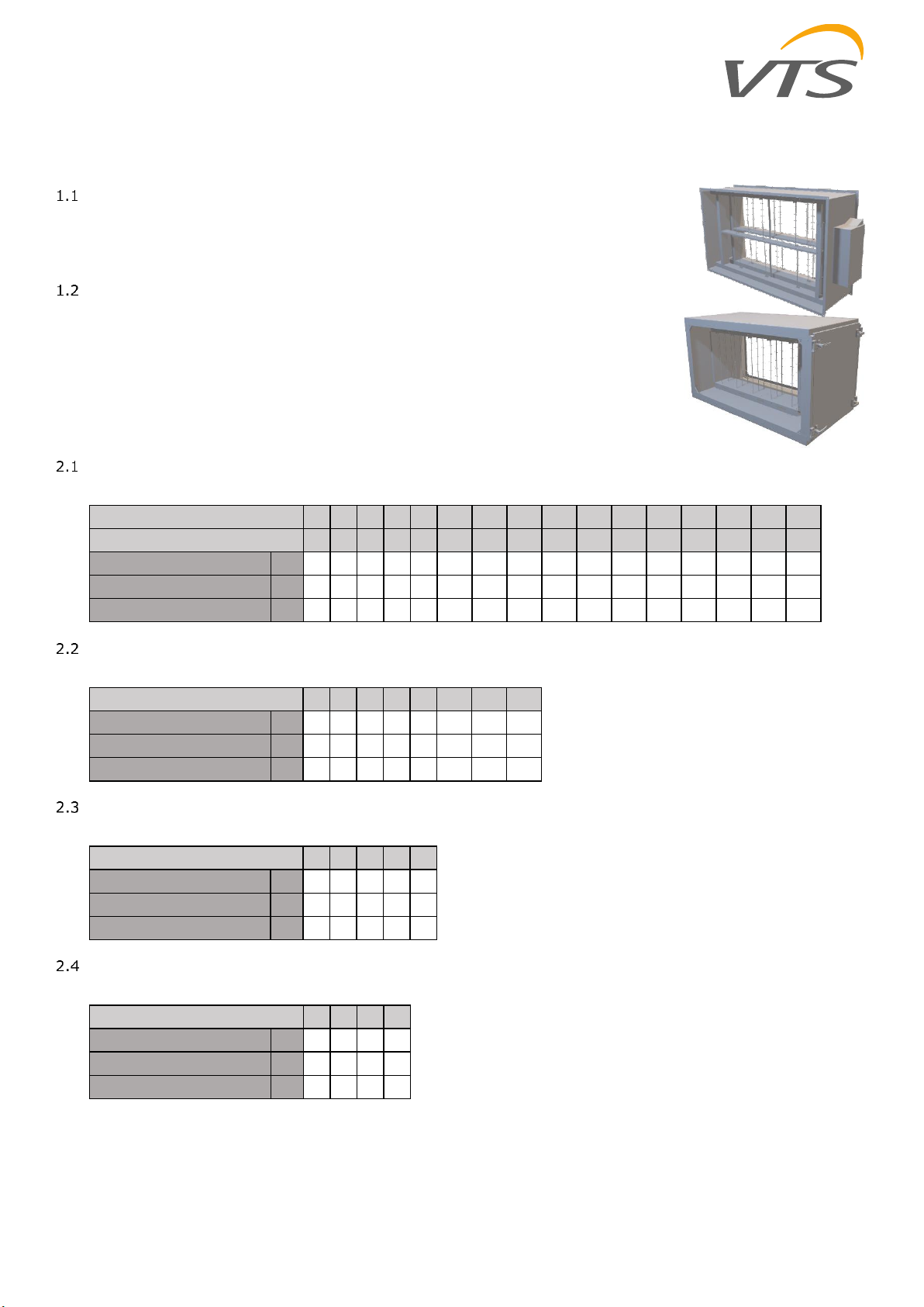
1.1 Electric heater in the non-insulated duct...................................................................................................................................1
1.2 Power slices in original AHU casing............................................................................................................................................1
2Range of the application ......................................................................................................................................................................1
2.1 VVS Standard & AVS...................................................................................................................................................................1
2.2 VVSc compact floor mounted air handling unit .........................................................................................................................1
2.3 VVSs suspended compact air handling unit ...............................................................................................................................1
2.4 NVS ducted air handling unit......................................................................................................................................................1
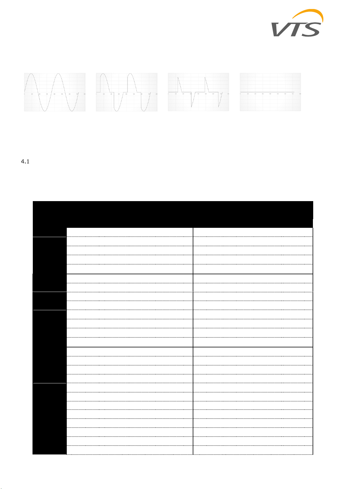
3SSR control...........................................................................................................................................................................................2
4Technical details...................................................................................................................................................................................2
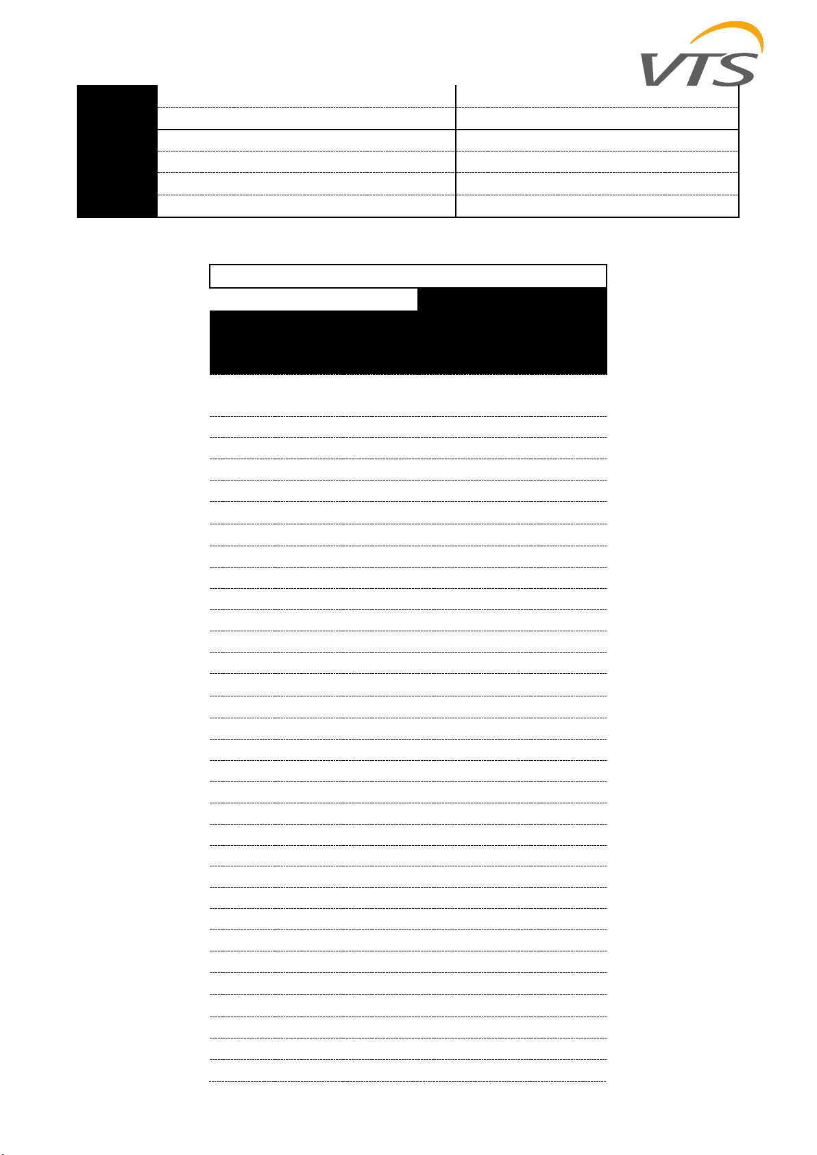
4.1 Power and current details..........................................................................................................................................................2
4.2 Electrical supply system details..................................................................................................................................................5
5Electrical connection............................................................................................................................................................................6
6Wiring cable types details....................................................................................................................................................................7
7Wiring schematics................................................................................................................................................................................8
7.1 1x18kW High power...................................................................................................................................................................9
7.2 1x18kW Low power..................................................................................................................................................................10
7.3 2x18kW High power.................................................................................................................................................................11
7.4 2x18kW low power ..................................................................................................................................................................12
7.5 4x18kW High power.................................................................................................................................................................13
7.6 4x18kW Low power..................................................................................................................................................................14
7.7 6x18kW High power.................................................................................................................................................................15
7.8 6x18kW Low power..................................................................................................................................................................17
8Maintenance Procedure ....................................................................................................................................................................19

1
VTS reserves the right to implement changes without prior notice
OMM_HE_SEC_ver 1.1
1Installation options
For the following AHU ranges: VVS Standard, AVS (with all subranges) and VVSc floor mounted units, the electric heater made of power slices
can be applied in two different ways:
Electric heater in the non-insulated duct
As per default, the electric heaters made of power slices will be available as shown on the rights. All power
slices will be simply installed in the short duct with the power junction box on the side.
Power slices in original AHU casing
If the electric heater needs to be a part of the AHU –in terms of being installed in the body of the unit –an
option of full assembly in the original casing will be available.
For this option, the heater and its power junction box will be installed inside the “empty section” of the
relevant air handling unit.
For such installation –the power slices will not be installed in the duct. The power slices will be directly
mounted to the internal surface of the AHU empty section.
2Range of the application
VVS Standard & AVS
For the VVS standard and AVS (with all subranges), the following heating power splits will be available for relevant AHU sizes:
VVSc compact floor mounted air handling unit
The VVSc compact floor mounted AHUs have electric heater power options as per below table:
VVSs suspended compact air handling unit
For the range of VVSs ceiling suspended unit, we have only 5 AHU sizes with heaters availability as listed below:
NVS ducted air handling unit
The NVS air handling units are the last where new power split for the electric heaters has been developed:
21 30 40 55 75 100 120 150 180 230 300 400 500 650
812 16 20 30 40 55 65 85 100 130 170 230 300 380
Max number of slices pcs 2 2 2 3 3 3 3 3 3 3 3 3 3 3 3 3
Individual slice capacity kW 12 18 18 18 24 30 30 36 36 36 36 36 36 36 36 36
Max total capacity kW 24 36 36 54 72 90 90 108 108 108 108 108 108 108 108 108
VVS Standard size
AVS Standard size
21 30 40 55 75 100 120 150
Max number of slices pcs 1 2 2 2 2 2 2 2
Individual slice capacity kW 18 18 24 30 30 36 36 36
Max total capacity kW 18 36 48 60 60 72 72 72
VVSc size
510 15 20 30
Max number of slices pcs 1 1 2 2 2
Individual slice capacity kW 10 12 18 18 18
Max total capacity kW 10 12 36 36 36
VVSs size
23 39 65 80
Max number of slices pcs 1 2 3 3
Individual slice capacity kW 18 18 18 24
Max total capacity kW 18 36 54 72
NVS size

2
VTS reserves the right to implement changes without prior notice
OMM_HE_SEC_ver 1.1
3SSR control
The idea of the SSR power regulation is based on cutting heater supplying voltage phases. See below charts, how the voltage supplying the
adjustable power slice changes depending on the required heating demand:
100% heating demand
70% heating demand
30% heating demand
0% heating demand (heater
off)
Each time the adjustable power slide reaches its full capacity, its effort is passed to the following slide which starts to run with its full capacity.
Any additional heating capacity will be realized by smooth increase of the adjustable power slide heating power.
4Technical details
Power and current details
High power
Low power
Heater
power
Slice
power
Slice qty
Total
power
Heater
power
Slice
power
Slice qty
Total
power
Device
[kW]
[kW]
-
[kW]
[kW]
[kW]
-
[kW]
VVS005s
5
10
1
10
1,25
2,5
1
2,5
VVS010s
6
12
1
12
1,5
3
1
3
VVS015s
6
18
2
36
2
6
1
6
VVS020s
6
18
2
36
2
6
1
6
VVS030s
6
18
2
36
2
6
1
6
VVS021c
6
18
2
36
2
6
1
6
VVS030c
6
18
3
54
2
6
1
6
VVS040c
6
24
3
72
1,5
6
1
6
VVS055c
6
30
3
90
1,5 / 2,0
9
1
9
VVS075c
6
30
3
90
1,5 / 2,0
9
1
9
VVS100c
6
36
3
108
2
12
1
12
VVS120c
6
36
3
108
2
12
1
12
VVS150c
6
36
3
108
2
12
1
12
VVS021
6
18
2
36
2
6
1
6
VVS030
6
18
3
54
2
6
1
6
VVS040
6
24
3
72
1,5
6
1
6
VVS055
6
30
3
90
1,5 / 2,0
9
1
9
VVS075
6
30
3
90
1,5 / 2,0
9
1
9
VVS100
6
36
3
108
2
12
1
12
VVS120
6
36
3
108
2
12
1
12
VVS150
6
36
3
108
2
12
1
12
VVS180
6
36
3
108
2
12
1
12
VVS230
6
36
3
108
2
12
1
12
VVS300
6
36
3
108
2
12
1
12
VVS400
6
36
3
108
2
12
1
12

3
VTS reserves the right to implement changes without prior notice
OMM_HE_SEC_ver 1.1
VVS500
6
36
3
108
2
12
1
12
VVS650
6
36
3
108
2
12
1
12
NVS23
6
18
1
18
2
6
1
6
NVS39
6
18
2
36
2
6
1
6
NVS66
6
18
3
54
2
6
1
6
NVS80
6
24
3
72
1,5
6
1
6
High power
L1/L2/L3
L1/L2/L3
Device
Total
power
[kW]
Control
box type
Current: wire 1
[A]
Current:
wire 2 [A]
VVS005s
10
1x18
21,6/12,5/12,5
-
VVS010s
12
1x18
26/15/15
-
VVS015s
18
1x18
26/26/26
-
VVS015s
36
2x18
52/52/52
-
VVS020s
18
1x18
26/26/26
-
VVS020s
36
2x18
52/52/52
-
VVS030s
18
1x18
26/26/26
-
VVS030s
36
2x18
52/52/52
-
VVS021
18
1x18
26/26/26
-
VVS021
36
2x18
52/52/52
-
VVS030
18
1x18
26/26/26
-
VVS030
36
2x18
52/52/52
-
VVS030
54
4x18
52/52/52
26/26/26
VVS040
24
2x18
41/41/26
-
VVS040
48
4x18
41/41/26
41/26/41
VVS040
72
4x18
52/52/52
52/52/52
VVS055
30
2x18
52/41/41
-
VVS055
60
4x18
52/52/52
41/41/26
VVS055
90
6x18
78/78/78
52/52/52
VVS075
30
2x18
52/41/41
-
VVS075
60
4x18
52/52/52
41/41/26
VVS075
90
6x18
78/78/78
52/52/52
VVS100
36
2x18
52/52/52
-
VVS100
72
4x18
52/52/52
52/52/52
VVS100
108
6x18
78/78/78
78/78/78
VVS120
36
2x18
52/52/52
-
VVS120
72
4x18
52/52/52
52/52/52
VVS120
108
6x18
78/78/78
78/78/78
VVS150
36
2x18
52/52/52
-
VVS150
72
4x18
52/52/52
52/52/52
VVS150
108
6x18
78/78/78
78/78/78
VVS180
36
2x18
52/52/52
-

4
VTS reserves the right to implement changes without prior notice
OMM_HE_SEC_ver 1.1
VVS180
72
4x18
52/52/52
52/52/52
VVS180
108
6x18
78/78/78
78/78/78
VVS230
36
2x18
52/52/52
-
VVS230
72
4x18
52/52/52
52/52/52
VVS230
108
6x18
78/78/78
78/78/78
VVS300
36
2x18
52/52/52
-
VVS300
72
4x18
52/52/52
52/52/52
VVS300
108
6x18
78/78/78
78/78/78
VVS400
36
2x18
52/52/52
-
VVS400
72
4x18
52/52/52
52/52/52
VVS400
108
6x18
78/78/78
78/78/78
VVS500
36
2x18
52/52/52
-
VVS500
72
4x18
52/52/52
52/52/52
VVS500
108
6x18
78/78/78
78/78/78
VVS650
36
2x18
52/52/52
-
VVS650
72
4x18
52/52/52
52/52/52
VVS650
108
6x18
78/78/78
78/78/78
NVS23
18
1x18
26/26/26
-
NVS39
18
1x18
26/26/26
-
NVS39
36
2x18
52/52/52
-
NVS65
18
1x18
26/26/26
-
NVS65
36
2x18
52/52/52
-
NVS65
54
4x18
52/52/52
26/26/26
NVS80
18
1x18
26/26/26
-
NVS80
36
2x18
52/52/52
-
NVS80
54
4x18
52/52/52
26/26/26
Low power
L1/L2/L3
Device
Total
power
[kW]
Control
box type
Current: wire 1
[A]
VVS005s
2,5
1x18
6,3/6,3/0
VVS010s
3
1x18
7,5/7,5/0
VVS015s
6
1x18
8,7/8,7/8,7
VVS020s
6
1x18
8,7/8,7/8,7
VVS030s
6
1x18
8,7/8,7/8,7
VVS021
6
1x18
8,7/8,7/8,7
VVS030
6
1x18
8,7/8,7/8,7
VVS040
6
1x18
13/7,5/7,5
VVS055
9
1x18
16,2/16,2/8,7
VVS075
9
1x18
16,2/16,2/8,7
VVS100
12
1x18
17,3/17,3/17,3
VVS120
12
1x18
17,3/17,3/17,3
VVS150
12
1x18
17,3/17,3/17,3

5
VTS reserves the right to implement changes without prior notice
OMM_HE_SEC_ver 1.1
VVS180
12
1x18
17,3/17,3/17,3
VVS230
12
1x18
17,3/17,3/17,3
VVS300
12
1x18
17,3/17,3/17,3
VVS400
12
1x18
17,3/17,3/17,3
VVS500
12
1x18
17,3/17,3/17,3
VVS650
12
1x18
17,3/17,3/17,3
NVS23
6
1x18
8,7/8,7/8,7
NVS39
6
1x18
8,7/8,7/8,7
NVS65
6
1x18
8,7/8,7/8,7
NVS80
6
1x18
8,7/8,7/8,7
Electrical supply system details
TN system
rated supply voltage
3x400V
insulation rated voltage
400V
rated impulse withstand voltage
2.5 kV
Rated short-time current Icw for individual circuits - effective
value of the periodic component withstood for 1 s, i.e. short-circuit current
expected at switching voltage
6 kA
rated short-circuit current 6 kA
rated coefficient of diversity 0.8
rated frequency 50 Hz ± 1 Hz
degree of protection IP00
permissible operating temperature 0 x 50 ° C
control circuits supply voltage 24 V DC

6
VTS reserves the right to implement changes without prior notice
OMM_HE_SEC_ver 1.1
5Electrical connection
Connecting power supply should be carried out with a separate switchgear, not supplied with the VTS package.
Connection of the heater should be done in a way to prevent from possibility of switching on the heater when the fan is not switched on. What
is more, if the fan stops, the heater's power supply must be turned off as well.
NOTICE! The thermostat must be absolutely installed in the heater control system.
Thermostat functionality is based on the bimetal element properties, resulting in opening the heater control circuit contacts at air temperature
near the thermostat up to 65ºC. After emergency turn off, the heater turns on automatically once the air temperature goes down by 20ºC.
After intended or emergency (caused by overheating) turning off the power supply, the supply–air fan has to operate for some time (0.5–5
min), so as the heater's coils reached their normal temperature.
Overheating thermostat
Functions and application
Protection module of the electric heater protecting it against overheating
Construction
Metal casing
Two screw terminals
bimetallic element with a function of a normally closed contact
Operation parameters
activation temperature: 65±3oC
hysteresis: 17±3oC
parameters of bimetallic element voltage: 30VDC permissible load.
Differential pressure control
Functions and application
Fan’s pile-up control
Construction
Membrane coupled with mechanical module. If the acceptable pressures difference is exceeded, the membrane undergoes deformation and
switches off
casing: plastic
Operation parameters
measurement: 20 –300 Pa:
rated operational voltage 30VDC
output signal: voltage-free (switching contact)
number of cycles: <106cycles
operation conditions: -30 –+85°C
protection class: IP44
Recommended pressure control operating position: horizontal. In case of vertical alignment, the set point value is 11Pa higher than the real
one.

7
VTS reserves the right to implement changes without prior notice
OMM_HE_SEC_ver 1.1
6Wiring cable types details
Power cord for electric heaters (voltage 3 ~ 400VAC)
Multi-core, copper conductor - twisted cable
Operating voltage U0 / U 450 / 750V
Working temperature -30- + 60C
Power cable for the control system (voltage 1 ~ 230VAC)
Multi-core, copper conductor - twisted cable
Working voltage U0 / U 300 / 500V
Working temperature -30- + 60C
Control cable for the control system (24VDC signals)
Multi-core, copper conductor - twisted cable
Working voltage U0 / U 300 / 500V
Working temperature -30- + 60C

8
VTS reserves the right to implement changes without prior notice
OMM_HE_SEC_ver 1.1
7Wiring schematics
High power and low power box contains the same elements –only difference is in the connection of the heaters. Electric heater supply wiring
should be let through the fixed panel, at the AHU's back. If the wiring is led through the inspection panel, on the front side, then it should be
arranged so as to enable opening the section for maintenance and service operations.
Dashed line CONNECTION MADE BY CUSTOMER
Solid line CONNECTION MADE BY MANUFACTURER
Terminal
number
Terminal
name
Signal name
Connect
to:
Type of control box
Connection terminal at the
control box
1
GND
Ground
->
CBX
GND
Compact
G0
Other
Ground
2
0-10V
0-10V DC
signal
->
CBX
Y1
Compact
Y1
Other
0-10V DC signal
3
24VDC
Supply
24VDC
voltage
->
CBX
G
Compact
G
Other
24VDC
Number of sections
1
2
3
4
St1
Start1
->
CBX
NO1
CBX
+24VDC
CBX
+24VDC
Compact
DO1
Compact
+24VDC
Compact
+24VDC
Other
+24VDC
Other
+24VDC
Other
+24VDC
5
St2
Start2
->
CBX
-
CBX
NO1
CBX
NO6
Compact
-
Compact
DO1
Compact
DO5
Other
-
Other
+24VDC
Other
+24VDC
6
St3
Start3
->
CBX
-
CBX
-
CBX
NO6
Compact
-
Compact
-
Compact
DO5
Other
-
Other
-
Other
+24VDC
L
L
Supply 230V
AC
->
Supply 230V AC
N
N
A1
A1
Confirmation
of work
->
CBX
DI2
Compact
DI2
Other
Potential-free contact
A2
A2
CBX
GND
Compact
G0
Other
Potential-free contact

9
VTS reserves the right to implement changes without prior notice
OMM_HE_SEC_ver 1.1
1x18kW High power

10
VTS reserves the right to implement changes without prior notice
OMM_HE_SEC_ver 1.1
1x18kW Low power

11
VTS reserves the right to implement changes without prior notice
OMM_HE_SEC_ver 1.1
2x18kW High power

12
VTS reserves the right to implement changes without prior notice
OMM_HE_SEC_ver 1.1
2x18kW low power

13
VTS reserves the right to implement changes without prior notice
OMM_HE_SEC_ver 1.1
4x18kW High power

14
VTS reserves the right to implement changes without prior notice
OMM_HE_SEC_ver 1.1
4x18kW Low power

15
VTS reserves the right to implement changes without prior notice
OMM_HE_SEC_ver 1.1
6x18kW High power

16
VTS reserves the right to implement changes without prior notice
OMM_HE_SEC_ver 1.1

17
VTS reserves the right to implement changes without prior notice
OMM_HE_SEC_ver 1.1
6x18kW Low power

18
VTS reserves the right to implement changes without prior notice
OMM_HE_SEC_ver 1.1
This manual suits for next models
30
Table of contents
Other VTS Medical Systems Electric Heater manuals
Popular Electric Heater manuals by other brands

Sentiotec
Sentiotec 160 Instructions for installation and use

Romus
Romus 93478 operating instructions

Olimpia splendid
Olimpia splendid CALEO GLASS Instructions for installation, use and maintenance

Sunred
Sunred CE11R User instructions

Olimpia splendid
Olimpia splendid OBLO' 2.2 Instructions for installation, use and maintenance

Eldom Invest
Eldom Invest RH01W Series manual