AEMC MA114 User manual

ENGLISH
User Manual
■
AC CURRENT PROBE
MA114

2AC Current Probe Model MA114
Statement of Compliance
Chauvin Arnoux®, Inc. d.b.a. AEMC®Instruments
certifies that this instrument has been calibrated using
standards and instruments traceable to international
standards.
We guarantee that at the time of shipping your
instrument has met its published specifications.
An N.I.S.T. traceable certificate may be requested at
the time of purchase, or obtained by returning the
instrument to our repair and calibration facility, for a
nominal charge.
The recommended calibration interval for this
instrument is 12 months and begins on the date of
receipt by the customer. For recalibration, please use
our calibration services. Refer to our repair and
calibration section at www.aemc.com.
Serial #:
Catalog #: 2153.41
Model #: MA114
Please fill in the appropriate date as indicated:
Date Received:
Date Calibration Due:
Chauvin Arnoux®, Inc.
d.b.a AEMC®Instruments
www.aemc.com

AC Current Probe Model MA114 3
CONTENTS
PRECAUTIONS FOR USE .................................................................................. 5
RECEIVING YOUR SHIPMENT ...................................................................... 6
1. DESCRIPTION................................................................................................. 7
1.1. GENERAL ................................................................................................ 7
1.2. MINIFLEX®MODEL MA114 ..................................................................... 7
2. OPERATION .................................................................................................... 8
2.1. MEASUREMENT PRINCIPLE.................................................................. 8
2.2. OPERATION ............................................................................................ 8
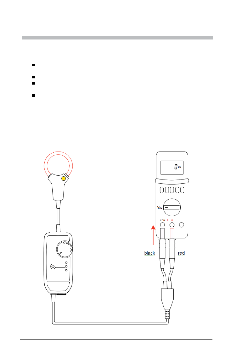
2.2.1. CONNECTING THE MA114 ............................................................. 8
2.2.2. DISCONNECTING THE MA114 ..................................................... 10
2.2.3. AUTOMATIC POWER OFF ............................................................ 10
2.3. EXTERNAL POWER (OPTIONAL)......................................................... 10
3. SPECIFICATIONS ......................................................................................... 12
3.1. REFERENCE CONDITIONS .................................................................. 12
3.2. ELECTRICAL CHARACTERISTICS....................................................... 12
3.3. VARIATIONS IN THE RANGE OF USE ................................................. 13
3.4. TYPICAL FREQUENCY RESPONSE GRAPHS .................................... 13
3.4.1. AMPLITUDE ERROR ..................................................................... 13
3.4.2. PHASE ERROR.............................................................................. 13
3.5. TYPICAL FREQUENCY RESPONSE GRAPHS .................................... 14
3.6. POWER SUPPLY................................................................................... 14
3.6.1. BATTERIES .................................................................................... 14
3.6.2. EXTERNAL POWER (OPTIONAL) ................................................. 14
3.7. ENVIRONMENTAL CONDITIONS ......................................................... 15
3.8. PHYSICAL SPECIFICATIONS ............................................................... 15
3.9. CONFORMITY TO INTERNATIONAL STANDARDS............................. 16
3.10. ELECTROMAGNETIC COMPATIBILITY (CEM) .................................. 16
4. MAINTENANCE ............................................................................................. 17
4.1. CLEANING ............................................................................................. 17
4.2. BATTERY REPLACEMENT ................................................................... 17
WARRANTY ...................................................................................................... 18

4AC Current Probe Model MA114
Thank you for purchasing the AEMC MiniFlex®MA114 flexible current sensor.
For best results from your instrument:
read these operating instructions carefully
comply with the precautions for use
WARNING, risk of DANGER! The operator must refer to these
instructions whenever this danger symbol appears.
CAUTION! Risk of electric shock. The voltage at the parts marked
with this symbol may be dangerous.
Equipment protected by double insulation.
Useful information or tip.
Application or withdrawal not authorized on conductors carrying
dangerous voltages. Type B current sensor as per IEC 61010-2-
032.
Battery.
Direction of current.
Recyclable in accordance with standard ISO14040.
Conforms with European directives and with regulations covering
EMC.
In the European Union, the product must undergo selective disposal
for the recycling of electric and electronic material, in compliance with
Directive WEEE 2002/96/EC.
Definition of Measurement Categories (CAT)
CAT IV Measurement category IV corresponds to measurements taken at the
source of low-voltage installations.
Examples: power feeders, counters and protection devices.
CAT III Measurement category III corresponds to measurements on building
installations.
Examples: distribution panel, circuit-breakers, machines or fixed
industrial devices.
CAT II Measurement category II corresponds to measurements taken on
circuits directly connected to low-voltageinstallations.
Examples: power supply to domestic electrical appliances and portable
tools.

AC Current Probe Model MA114 5
PRECAUTIONS FOR USE
The MA114 is protected against voltages up to 600 V with respect to earth in
measurement category IV, or 1000 V in category III. The protection assured by
the current sensor can be compromised if it is used in a way that is not
recommended by the manufacturer.
Comply with the rated maximum voltage and current and the
measurement category.
Never exceed the protection limits stated in the specifications.
Comply with the conditions of use (temperature, humidity, altitude,
degree of pollution and location of use).
Do not use the MA114 if it is open, damaged, or incorrectly reassembled.
Before each use, check the integrity of the insulation on the coil, the
leads, and the electronic unit.
The application or withdrawal of the sensor on uninsulated conductors at
dangerous voltages requires the use of suitable safety equipment.
If it is not possible to power down the installation, follow safe operating
procedures and usesuitable means of protection.
All troubleshooting and metrological checks must be done by competent,
accredited personnel.

6AC Current Probe Model MA114
Receiving Your Shipment
Upon receiving your shipment, make sure that the contents are consistent with
the packing list. Notify your distributor of any missing items. If the equipment
appears to be damaged, file a claim immediately with the carrier and notify your
distributor at once, giving a detailed description of any damage. Save the
damaged packing container to substantiate your claim.
Ordering Information
MiniFlex®14” Model MA114 (3A/1V/A, 30A/100mV/A,
300A/10mV/A, 3000A/1mV/A)...................................................... Cat #2153.41
Includes two 1.5 V batteries (AA or LR6), multilingual safety data sheet, user
manual, and verification certificate.

AC Current Probe Model MA114 7
1. INTRODUCTION
1.1. GENERAL
MiniFlex®sensors consist of a flexible coil connected by a shielded lead to a
housing containing the signal processing electronics, powered by batteries. The
flexibility of the sensors allows clamping of the conductor to be measured,
whatever its shape (cable, bar, strand, etc.) and accessibility. The snap-locking
coil opening/closing button allows handling while wearing protective gloves. The
electronic unit can be connected to the mVAC or VAC input of a measuring
instrument having an input impedance of ≥ 1 MΩ.
1.2. MINIFLEX®MODEL MA114
MiniFlex®MA114 single‑phase 14” (35 cm) sensor converts alternating currents
ranging from 3 to 3000 A into proportional AC voltages.
Flexible coil
Banana plugs (2), 0.16”
(4 mm) diameter
Sensor opening
button
OL indicator (red):
indicates reading
exceeds measurement
range
Shielded cable
Switch to activate
instrument and
select sensitivity
Auto Power OFF
indicator (orange): auto
OFF feature activated
Auto Power OFF
button deactivates
auto OFF feature
ON indicator (green):
Blinking: running on
battery power
Steady: running on
external power
Type B Micro-USB
port to connect
optional 5 V external
power supply
Connecting cable
connecting the
electronic unit to a
display instrument

8AC Current Probe Model MA114
2. OPERATION
2.1. MEASUREMENT PRINCIPLE
The MA114 sensor is based on the Rogowski coil principle. This provides:
very good linearity and no saturation effect (and therefore no
overheating)
wide measurement dynamic, up to several kA
insensitivity to DC (measurement of the AC component of any AC + DC
signal)
light weight (no magnetic circuit)
2.2. OPERATION
2.2.1. CONNECTING THE MA114
1. Connect the output leads to a measuring instrument (for example a
multimeter) having an input impedance ≥1 MΩ. Turn it ON and set to
AC voltage measurement.

AC Current Probe Model MA114 9
2. Turn the instrument ON by turning the rotary switch to any position. The
green ON indicator starts blinking.
3. Press on the yellow sensor opening button to open the flexible coil.
4. Place the open sensor around conductor to be measured (only one
conductor in the sensor at a time). Close the coil; an audible click
sounds as the coil is closed.
Use individual protection equipment when measuring an
uninsulated conductor carrying a high voltage.
To optimize measurement, center the conductor in the coil.
5. Set the switch to the range providing the best sensitivity and ensure the
red OL indicator is off. (OL indicates saturation of the electronics,
resulting in a measurement error.)

10 AC Current Probe Model MA114
6. Read the measurement on the multimeter, applying the reading
coefficient indicated on the label on the electronic unit corresponding to
the setting of the switch.
3A~ range: 1000 mV~/A~
30 A~ range: 100 mV~/A~
300 A~ range: 10 mV~/A~
3000 A~ range: 1 mV~/A~
7. Multiply the reading by the coefficient.
For example, a reading of 1 V on the measuring instrument corresponds
to a current of
1V
10 mV/A= 100 A in the 300 A~ range.
2.2.2. DISCONNECTING THE MA114
Remove the flexible coil from the conductor, set the switch to OFF, and
disconnect the electronic unit from the multimeter.
2.2.3. AUTOMATIC POWER OFF
When the MA114 starts up, it operates for 10 minutes, then automatically
switches itself to sleep mode to save battery life. While this feature is activated,
the orange Auto Power Off indicator is lit.
To override automatic power off:
1. With the MA114 OFF, press and hold down the Auto Power Off button
while turning the sensor ON by turning the switch to any measurement
setting.
2. Continue to hold down Auto Power Off for longer than 2 seconds. The
orange Auto Power Off indicator remains OFF, indicating this feature is
disabled.
2.3. EXTERNAL POWER (OPTIONAL)
For long‑duration measurements, you can connect the MA114’s electronic unit to
line power. Remove the protection from the type B micro‑USB connector, then
connect the lead. You can use any line/micro‑USB adapter that delivers 100 mA
or more.
The green On indicator remains lit but its brightness varies to indicate the
batteries are functional. While external power supply is present, automatic power
off is disabled. If external power is disconnected, the MA114 switches to battery
power and automatic power off takes effect after 10 minutes.

AC Current Probe Model MA114 11
If you make long‑duration recordings, you must deactivate automatic power OFF
(see § 2.2.3).
The insulation between the type B micro‑USB connector and the measurement
output is 1000 V CAT III or 600 V CAT IV. That makes it possible to safely
connect the instrument to wattmeters with uninsulated inputs. The type B
micro‑USB connector must not be in contact with conductors or uninsulated
material at dangerous voltages.

12 AC Current Probe Model MA114
3. SPECIFICATIONS
3.1. REFERENCE CONDITIONS
Quantity of influence
Reference values
Temperature
77 ± 9 °F (23 ± 5 °C)
Relative humidity
20 to 75 % RH
Measurement frequency range
30 to 440 Hz
Type of signal
sinusoidal
Instrument turn-on time
1 minute
External electric field
null
External DC magnetic field (earth's field)
< 40 A/m
External AC magnetic field
null
Position of the conductor in the coil
centered
Shape of the measurement coil
circular, no applied stress
Input impedance of the instrument connected
to the electronic unit ≥1 MΩ
3.2. ELECTRICAL CHARACTERISTICS
Parameter
Value
Range 3 A
30 A
300 A
3000 A
Specified measurement
range 0.5 to 3 A
2 to 30 A
5 to 300 A
50 to 3000 A
Output/input ratio (mV~/A~)
1000
100
10
1
Maximum peak factor 1.5 at IN(I nominal)
Intrinsic uncertainty
(% of output signal)
≤1%
+ 40 mV
≤1% + 4 mV
≤1.5% + 0.4 mV (I<10% IN)
≤1% + 0.4 mV (I≥10% IN)
≤1.5%+ 0.04 mV (I<10% IN)
≤1% + 0.04 mV (I≥10% IN)
Maximum offset voltage
0 mV
DC
Phase shift at 50 Hz
≤1° (0.5° typical)
Max. output voltage
-4.5 Vpeak ≤ V ≤ + 4.5 Vpeak
Frequency response
*10 Hz to 10 kHz
10 Hz to 20 kHz
*Above 300 ARMS, see the graph in § 3.5.
The peak value is limited only by the electronics of the measurement
unit (red OL indicator on). The coil alone can briefly withstand higher
peak factors with no risk of overheating or damage.

AC Current Probe Model MA114 13
3.3. VARIATIONS IN THE RANGE OF USE
Quantity of influence Range of influence
Error in % of reading
Typical
Maximum
Battery voltage
1.8 to 3.2 V
0.02%
0.1%
Temperature
10 to 55 °C
0.15% / 10 °C
0.50% / 10 °C
Relative humidity
10 to 90% RH
0.2%
0.5%
USB supply voltage
5 V
0.5%
1.5%
Position of the conductor in
the undeformed sensor
Any position 1% 2.5%
Adjacent conductor
carrying an AC voltage
Conductor touching sensor
0.2%
1% (2% near
snap lock)
Deformation of the sensor
Oblong shape
0.2%
1%
Common mode rejection
600 V between the jacket
and the secondary
100 dB 80 dB
Input impedance of the
measuring instrument
10 kΩto 1 MΩ0.1%
3.4. TYPICAL FREQUENCY RESPONSE GRAPHS
3.4.1. AMPLITUDE ERROR
3.4.2. PHASE ERROR

14 AC Current Probe Model MA114
3.5. TYPICAL FREQUENCY RESPONSE GRAPHS
In the 3A, 30A, and 300A ranges, with a frequency ≤20 kHz, there is no
frequency derating.
3.6. POWER SUPPLY
3.6.1. BATTERIES
The MA114 is powered by two 1.5 V alkaline batteries (type AA or LR6). The
nominal operating voltage is between 1.8 and 3.2 V.
The mean battery life is:
300 hours in continuous operation
1,800 10‑minute measurements
When the MA114 is not connected to line power and the green On indicator goes
off, the batteries must be replaced (see § 4.2).
3.6.2. EXTERNAL POWER (OPTIONAL)
The MA114 can be powered by a standard line adapter (5 VDC, 100 mA) with a
type B micro‑USB connector.
When the adapter is connected and the switch is set to OFF, the On indicator is
lit steadily.
When the MA114 is ON, the brightness of the On indicator varies to indicate that
the batteries are functional. If the indicator remains on steadily, the batteries
must be replaced.

AC Current Probe Model MA114 15
3.7. ENVIRONMENTAL CONDITIONS
The MA114 must be used in the following conditions:
1: Range of reference
2: Operating range
3: Storage range (without battery)
If the MA114 will be unused or stored for an extended period, remove its
batteries. The sensor by itself can withstand a maximum temperature of 194°F
(90°C) for 10 minutes.
Degree of pollution: 2
Altitude: < 6500’ (2000 m)
3.8. PHYSICAL SPECIFICATIONS
Coil:
Length: 14” (35 cm)
Clamping diameter: 4” (10 cm)
Shielded lead between the sensor and the electronic unit:
Diameter: 0.16” (4 mm)
Length: 78.7” (2 m)
Electronic unit:
Dimensions: 4.72 x 2.28 x 1.42” (120 x 58 x 36 mm)
Output cable:
Length: 19.7” (50 cm) Diameter
(2 plugs): 0.16” (4 mm)
Weight: approximately 10.5 oz (300 g).
Protection index: IP 54 for the electronic unit and IP 67 for the flexible sensor
per IEC 60529. The flexible coil withstands oils and aliphatic hydrocarbons well.

16 AC Current Probe Model MA114
3.9. CONFORMITY TO INTERNATIONAL STANDARDS
Electrical safety per IEC 61010‑2‑032 for type B sensors.
Double insulation
Measurement category: IV
Rated voltage: 600 V (or 1000 V in CAT III)
3.10. ELECTROMAGNETIC COMPATIBILITY (CEM)
Emissions and immunity in an industrial environment per IEC 61326‑1.

AC Current Probe Model MA114 17
4. MAINTENANCE
Except for the batteries, the MA114 contains no parts that can be replaced by
personnel who have not been specially trained and accredited. Any unauthorized
repair or replacement of a part by an “equivalent” may significantly impair safety.
4.1. CLEANING
Disconnect the unit completely and turn the rotary switch to OFF.
Wipe with a soft cloth, dampened with soapy water.
Rinse with a damp cloth and dry rapidly with a dry cloth or forced air. Do
not use alcohol, solvents, or hydrocarbons.
Ensure no foreign body interferes with the operation of the snap lock
button of the sensor.
4.2. BATTERY REPLACEMENT
The batteries must be replaced when the On indicator remains off upon power-
up.
1. Disconnect the sensor completely and turn the rotary switch to OFF.
2. Use a screwdriver to remove the two screws closing the electronic unit.
3. Replace the spent batteries with new batteries (1.5V AA or LR6 alkaline
batteries).
4. Insert the batteries in their compartment, taking care to ensure correct
polarities.
5. Close the electronic unit and make sure that it is completely and
correctly closed.
6. Screw the two screws back in.

18 AC Current Probe Model MA114
WARRANTY
Your AEMC instrument is warranted to the owner for a period of two years from
the date of original purchase against defects in manufacture. This limited
warranty is given by AEMC®Instruments, not by the distributor from whom it was
purchased. This warranty is void if the unit has been tampered with, abused, or if
the defect is related to service not performed by AEMC®Instruments.
Full warranty coverage and product registration is available on our website at:
www.aemc.com/warranty.html.
Please print the online Warranty Coverage Information for your records.
What AEMC®Instruments will do:
If a malfunction occurs within the two-year period, you may return the instrument
to us for repair, provided we have your warranty registration information on file or
a proof of purchase. AEMC®Instruments will, at its option, repair or replace the
faulty material.
WARRANTY REPAIRS
What you must do to return an instrument for Warranty Repair:
First, request a Customer Service Authorization Number (CSA#) by phone or by
fax from our Service Department (see address below), then return the instrument
along with the signed CSA Form. Please write the CSA# on the outside of the
shipping container. Return the instrument, postage or shipment pre-paid to:
Ship To: Chauvin Arnoux®, Inc. d.b.a. AEMC®Instruments
15 Faraday Drive • Dover, NH 03820 USA
Phone: (800) 945-2362 (Ext. 360)
(603) 749-6434 (Ext. 360)
Fax: (603) 742-2346 • (603) 749-6309
E-mail: [email protected]om
Caution: To protect yourself against in-transit loss, we recommend you insure
your returned material.
NOTE: You must obtain a CSA# before returning any instrument.

AC Current Probe Model MA114 19
NOTES:
Table of contents
Other AEMC Test Equipment manuals