Wachendorff ur3274 User manual

UR3274 Controller
User manual
Version 1.0

2 UR3274U - User manual
Summary
1 Safety instructions........................................................................... 5
1.1 General instructions .............................................................. 5
1.2 Intended Usage ...................................................................... 6
1.3 Qualied personnel ............................................................... 6
1.4 Remaining hazards ............................................................... 6
1.5 CE Conformity ......................................................................... 7
2 Model Identication........................................................................ 7
3 Technical Data.................................................................................. 7
3.1 General Features..................................................................... 7
3.2 Hardware Features................................................................. 8
3.3 Software Features .................................................................. 9
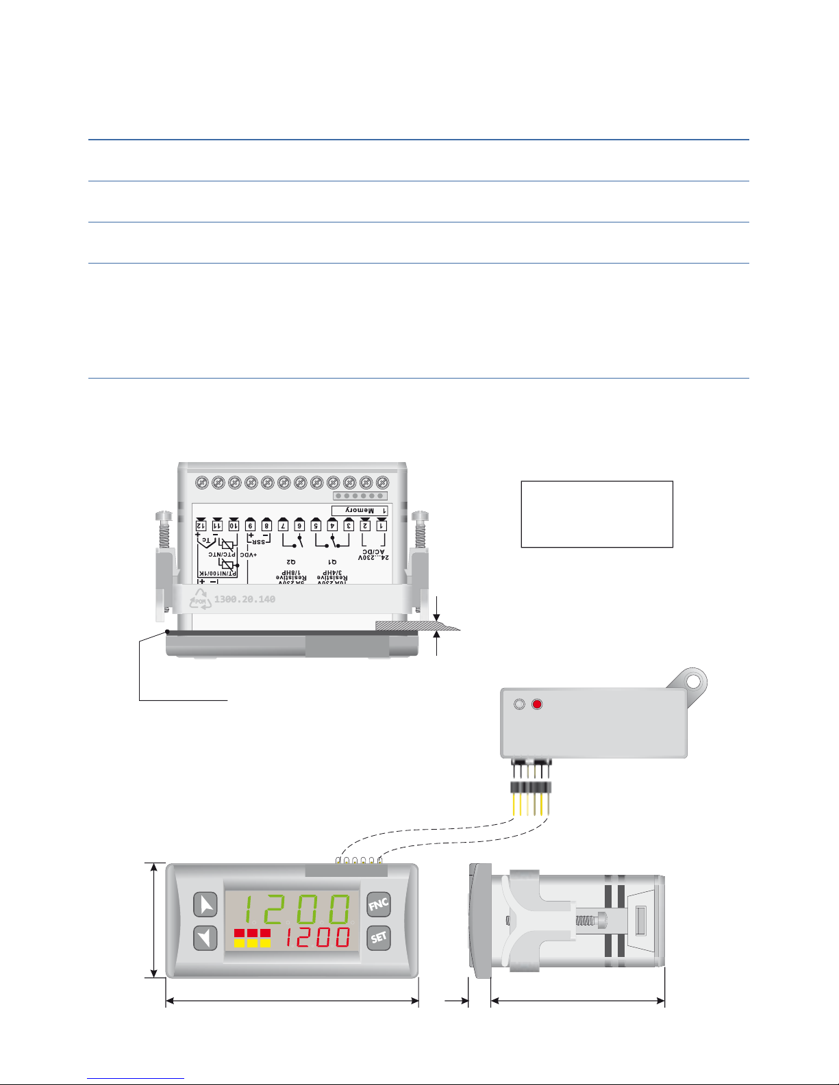
4 Dimensions and Installation......................................................... 9
5 Electrical wirings ..........................................................................10
5.1 Wiring diagram.....................................................................10
6 Display and Keys Functions.........................................................14
6.1 Numeric Indicators (Display).............................................14
6.2 Meaning of Status Lights (Led) .........................................14
6.3 Keys .......................................................................................15
7 Controller Functions......................................................................15
7.1 Modifying Main Setpoint and Alarm Setpoint Values.15
7.2 Auto-Tune...............................................................................16
7.3 Manual Tuning......................................................................16
7.4 Automatic Tuning ...............................................................16
7.5 Soft Start.................................................................................17
7.6 Automatic/Manual Regulation for % Output Control 17
7.7 Pre-Programmed Cycle.......................................................18
7.8 Programming module ........................................................18
7.9 Loading default values........................................................19

UR3274U - User manual 3
7.10 LATCH ON Functions............................................................20
7.11 Digital Input Functions .......................................................22
7.12 Dual Action Heating-Cooling............................................23
8 Timer operation..............................................................................25
8.1 Single Timer...........................................................................26
8.2 Dual Timer..............................................................................26
8.3 Dual Sequential Timer ........................................................27
8.4 Dual Timer Loop ..................................................................27
8.5 Relating Timers to Alarms .................................................28
9 Serial Communication........................................................29
9.1 Slave .......................................................................................29
9.2 Master .....................................................................................35
9.2.1 Master Mode in retransmission.............................35
9.2.2 Master Mode Remote process................................37
10 Conguration .................................................................................37
10.1 Modify Conguration Parameter.....................................37
11 Table of Conguration Parameters ...........................................38
12 Alarm Intervention Modes...........................................................53
13 Table of Anomaly Signals.............................................................57
14 Summary of Conguration parameters...................................58

4 UR3274U - User manual
Introduction
Dear valued Customer!
Thank you for purchasing and using a product from our com-
pany. The compact universal controller UR3274U integrates
in a single device multiple options for sensor reading and
actuators command in addition to the extended supply range
24 to 230 Vac/Vdc. With 17 selectable sensors and outputs
congurable as relay or SSR command the user can reduce
stock needs.
The series includes also a model with serial communication
RS485 Modbus RTU. The possibility to repeat parametrization
is simplied by the programming module with internal batte-
ry that do not require power supply for the controller
For getting the highest eort out of this unit, we kindly ask
you to follow the below mentioned instructions:
Every person who is involved with the installation or usage of
this unit, must read carefully and understand the installation
manual and safety instructions!
Safety instructions
. General instructions
To ensure the safe operation of this unit the instructions that
appear in this manual must be strictly observed. In addition,
when used all applicable legal and safety regulations for the
respective application must be observed. The same applies
correspondingly to the use of accessories.

UR3274U - User manual 5
. Intended Usage
Units from the controller series UR3274U are used for di-
splaying and monitoring of process values. Any other use is
regarded not in accordance with the intended usage.
Units from the controller series UR3274U are not meant to be
used as sole safety means to prevent dangerous situations on
machinery and installations. Machinery and intallations must
be so designed that fault conditions can not lead to harmful
situations to operating personnel (e.g. by independent limit
value switches, mechanical locking etc.).
. Qualied personnel
Units from the controller series UR3274U must only be
operated in accordance with the technical specications by
qualied personnel. Personnel regarded qualied is familiar
with the installation, assembly, putting into operation and
operation of the units and possesses adequate professional
qualication for the task.
. Remaining hazards
Units from the controller series UR3274U are state of the art
and safe to operate. A risk of danger can occur when deplo-
yed and operated improperly by untrained personnel.

6 UR3274U - User manual
In this manual remaining hazards are marked by the following
warning symbol:
This symbol indicates that non-observance of the
safety guidelines may cause hazards to persons
even serious injury or death and/or the possibility
of property damage.
. CE Conformity
The CE certicate is available at our company. We are pleased
to send you a copy of it. Please feel free and contact us to get
a copy.
Model Identication
Refer to the table below to easily select preferred model.
All versions available with power … Vac/Vdc +/-%
/Hz – ,VA
URU relays (A+A) + SSR
URU relays A + Ssr + RS
Technical Data
. General Features
Display . inch displays + . displays
Operating
temperature relays A + Ssr + RS
Sealing IP front panel (with gasket)
IP box, IP terminals
Material Polycarbonate ULV self-extinguishing
Weight g

UR3274U - User manual 7
. Hardware Features
Analogue
input
AN. Congurable
via software.
Thermocouple type:
K, S, R, J. Automatic
compensation of cold
junction from °C to
°C.
Thermoresistance:
PT, PT, PT,
Ni, PTCK, NTCK
(β K). Linear: -V,
- or -mA, -mV
Potentiometers:
K, K,
Tolerance (°C)
+/-. % ± digit for
thermocouple input,
thermo- resistance and
V/mA.
Cold junction accuracy
.°C/°C
Impedance:
-V: Ri>K
-mA: Ri<
-mA: Ri<
-mV: Ri>M
Relay
output
relays (URU)
relay (URU)
Congurable as
command and/or alarm
output
Contacts:
Q: A-V~
for resistive loads
Q: A-V~
for resistive loads
SSR
output
SSR Congurable as
command output and/
or alarm output.
Vdc/mA
Supply
Power supply
.. Vac/Vdc +/-%
/Hz
Power consumption
.VA

8 UR3274U - User manual
. Software Features
Regulation
algorithms
ON-OFF with hysteresis.
P, PI, PID, PD with proportional time
Proportional band ...°C or °F
Integral time ,..., sec ( excluded)
Derivative time ,..., sec ( excluded)
Controller
functions
Manual or automatic Tuning, congurable
alarms, protection of command and alarm
setpoints, activation of functions via
digital input, preset cycle with Start/Stop.
Dimensions and Installation
U1
CN1
1 6
123
77 mm
35 mm
53 mm
7
CN1
1 6
Gasket for 32x74
Suggested thickness 2 ÷ 8 mm
28.5 x 70.5 mm
Frontal panel cut-out
Programming Module with battery

UR3274U - User manual 9
Electrical wirings
Although this controller was designed to resist
electromagnetic interferences in industrial envi-
ronments, pease observe following safety guide-
lines:
• Separatethefeederlinefromthepowerlines.
• Avoid placing near units with remote control switches,
electromagnetic contactors, high powered motors and in
all instances use specic lters.
• Avoidplacingnearpowerunits,particularlyifphasecon-
trolled.
. Wiring diagram
UR3274U5 UR3274U6
I
Programmin module
Controller, 2 SW, Relais/SSR
Supply: 24...230 Vac/dc; 4,6 VA
P/N: UR3274U5
wp-direkt.de
24...230V
AC/DC
8A230V
Resistive
1/2HP
Q1
5A230V
Resistive
1/8HP
Q2
SSR
+VDC
Tc
PTC/NT C
PT/NI100/1K
2 wire
Power
4/20mA
V/I
1Programmin module1
1 2 3 4 5 6 7 8 9 10 11 12
Controller, 2 SW, RS485
Supply: 24...230 Vac/dc; 4,6 VA
P/N: UR3274U6
wp-direkt.de
24...230V
AC/DC
8A230V
Resistive
RS485 SSR
+VDC
Tc
PTC/NT C
PT/NI100/1K
2 wire
Power
4/20mA
V/I
1 2 3 4 5 6 7 8 9 10 11 12
Power Supply
1 2
24...230V
AC/DC
Switching power supply with extended
range
… Vac/dc ±% /Hz – ,VA.

10 UR3274U - User manual
AN Analogue Input
Tc
11 12
Shield
For thermocouples K, S, R, J.
• Complywithpolarity
• Forpossibleextensions,use
compensated cable and terminals
suitable for the thermocouples
used(compensated)
• Whenshieldedcableisused,itshould
be grounded at one side only
10 11 12
PT/NI100
Shield
A
B
C
For thermoresistances PT, NI
• Forthethree-wireconnectionuse
wires with the same section
• Forthetwo-wireconnectionshort-
circuit terminals 10 and 12
• Whenshieldedcableisused,itshould
be grounded at one side only
RED
WHITE
RED
10
11
12
Shield
PTC/NTC
10 11
For thermoresistances NTC, PTC,
PT, PT e potentiometers
• Whenshieldedcableisused,itshould
be grounded at one side only to avoid
ground loop currents
Shield
+VDC
910 11 12
V/I +-
For linear signals V/mA
• Complywithpolarity
• Whenshieldedcableisused,itshould
be grounded at one side only

UR3274U - User manual 11
Examples of Connection for linear input
0...10V
1112
For signals ….V
• Complywithpolarity
PRESSURE TRANSMITTER
0/4...20mA
A
B
C
1112 9
For signals /….mA with three-wire
sensor
• Complywithpolarity
C = Sensor output
B = Sensor ground
A = Sensor power
EXTERNAL SUPPLY
PRESSURE TRANSMITTER
0/4...20mA
B
C
1112
For signals /..mA with external
power of sensor
• Complywithpolarity
C = Sensor output
B = Sensor ground
PRESSURE TRANSMITTER
C
4...20mA
A
12 9
For signals /...mA with two-wire
sensor
• Complywithpolarity
C = Sensor output
A = Sensor power supply
Serial input
1176
-
+
Shield
RS485
RS Modbus RTU communication
Do not use LT (line termination)
resistors
• Fornetworkswithmorethanve
instruments supply in low voltage

12 UR3274U - User manual
Relay Q Output
7 6 5 4
Q1
Q2
3
Capacity:
Q: 8A, 250Vac,resistive loads,10opera-
tions. 30/3A, 250Vac, cosφ=0.3, 10
operations.
Q: 5A, 250Vac, resistive loads, 105
operations.
20/2A, 250Vac, cosφ=0.3, 10ope-
rations.
SSR output
SSR
8 9
SSR command output 12V/30mA
Digital Input
10 11
Digital input according to parameter
DGT.i .
The use of digital input in this version is
possible only with TC sensors or …V,
/…mA and …mV signals

UR3274U - User manual 13
Display and Keys Functions
5
4
38
7
62
1
M T R
2 3
9
10
12
11
1
. Numeric Indicators (Display)
1234
Normally displays the process. During the
conguration phase, it displays the parameter
being inserted.
1234
Normally displays the setpoint. During the
conguration phase, it displays the parameter
value being inserted.
. Meaning of Status Lights (Led)
1
ON when the output command is on. For
motorised valve command, led is ON when valve is
opening and blinks when closing.
2ON when alarm is on.
3ON when alarm is on.
MON when the “Manual” function is on.
TON when the controller is running an “Autotuning”
cycle.
RON when the controller communicates via serial
port.

14 UR3274U - User manual
. Keys
• Allowstodecreasemainsetpoint.
• Duringcongurationphase,allowstoslide
through parameters. Together with
SET
key it
modies them.
• Pressedafter
SET
key it allows to decrease
alarm setpoint.
• Allowstoincreasemainsetpoint.
• Duringcongurationphase,allowstoslide
through parameters. Together with
SET
key it
modies them.
• Pressedafter
SET
key it allows to increase alarm
setpoint.
SET
• Allowstodisplayalarmsetpointandrunsthe
autotuning function.
• Allowstomodifycongurationparameters.
FNC
• Allowstoruntheautotuningfunctionandto
select Manual/automatic operation.
•
Allows to enter/exit for congurator procedure.
Controller Functions
. Modifying Main Setpoint and Alarm
Setpoint Values
Setpoint value can be changed by keyboard as follows:
Press Eect Do
or Value on display
changes
Increase or decrease
main setpoint
SET
Visualize alarm
setpoint on display
or Value on display
changes
Increase or decrease
the alarm set point
value

UR3274U - User manual 15
. Auto-Tune
Tuning procedure calculates the controller parameters and
can be manual or automatic according to selection on para-
meter 46
tune
.
. Manual Tuning
Manual procedure allows the user greater exibility to decide
when to update PID algorithm work parameters. The proce-
dure can be activated in two ways.
• RunningTuningbykeyboard:
Press
FNC
key until display 1 shows the writing
tune
with
display 2 showing
o FF
, press , display 2 shows
on
. The
Tled switches on and the procedure begins.
• RunningTuningbydigitalinput:
Select
tune
on parameter 50
d Gt.i .
At rst activation of digital input (commutation on front panel)
T
led switches ON and at second activation switches o.
. Automatic Tuning
Automatic tuning activates whenever the controller is switched
on or when the setpoint is modied to a value over 35%.
To avoid an overshoot, the treshold where the controller calcu-
lates new PID parameters is determined by the setpoint value
minus the “Set Deviation Tune” (see Parameter 47
s.d.tu.
).
To exit Tuning and keep PID values unchanged, just press the
FNC
key until display 1 shows the writing
tune
with the display
showing
on
, press , display 2 shows
off
.
The
T
led switches o and the procedure nishes.

16 UR3274U - User manual
. Soft Start
To reach the setpoint the controller can follow a gradient
expressed in units (e.g. degree/hour).
Enter this gradient on parameter 51
Grad.
with the chosen
units/hour; only on subsequent activation the controller
uses soft start function.
Automatic/manual tuning cannot be enabled if the Soft start
is active.
. Automatic/Manual Regulation for %
Output Control
This function allows to select automatic functioning or ma-
nual command of the output percentage.
Parameter 49
Au.ma.
, can select two methods.
• Firstselection
en.
pressing the
FNC
key display 1 shows
p.---
, while display 2
shows
Auto
.
Press the key to select
man.
mode; it is now possible, to
change the output percentage using the keys and
. To return to automatic mode, using the same procedure,
select
auto
on display 2: Mled switches o and functio-
ning returns to automatic mode.
• Secondselection
en.st.
same functioning, but with two important variants:
• Ifthereisatemporarypowerfailureorafterswitch-o,
manual functioning as well as the previous output
percentage value will be maintained at restarting.
• Ifthesensorbreaksduringautomaticfunctioning,con-
troller moves to manual mode while maintaining the

UR3274U - User manual 17
output percentage command unchanged as generated
by the PID immediately before breakage.
. Pre-Programmed Cycle
Pre-programmed cycle function activates by setting
p r. cY.
on
parameter 48
o p.Mo .
Controller reaches setpoint1 basing on the gradient set on pa-
rameter 51
Grad.
, then it reaches max. power up to setpoint2.
When the process reaches max. power, this setpoint is main-
tained for the time set on parameter 52
m a . t.i .
At expiry, process will reach ambient temperature according
to gradient entered on parameter 64
f a .G r.
, then command
output will be disabled and display will visualize
Stop
.
Setpoint
Time
Setpoint 1
Setpoint 2
Maintenance time
Cooling
Max Power
Rising gradient
Cycle starts at each activation of the controller, or via digital
input if it is enabled for this type of functioning (see parame-
ter 50
d Gt.i .
).
. Programming module
Parameters and setpoint values can be duplicated from one
controller to another using the Programming module.
There are two methods:
• Withthecontrollerconnectedtothepowersupply

18 UR3274U - User manual
Insert the programming module when the controller is o.
On activation display 1 shows
memo
and display 2 show
----
(Only if the correct values are saved in the program-
ming module). By pressing the key display 2 shows
Lo a d
, then conrm using the
FNC
key. The controller loads
the new data and starts again.
• Withthecontrollernotconnected
to power supply.
The programming module is equip-
ped with an internal battery with an
autonomy of about 1000 uses.
Insert the programming module
and press the programming button .
When writing the parameters, the led turns red and on
completing the procedure it changes to green. It is possible
to repeat the procedure without any particular attention.
Updating programming module
To update the programming module values, follow the proce-
dure described in the rst method, setting display 2 to
----
so
as not to load the parameters on controller.
Enter conguration level and change at least one parameter.
Exit conguration. Changes are saved automatically.
. Loading default values
This procedure allows to restore factory settings of the
instrument.
If on activation the controller does not display
memo
it means no data
have been saved on the programming module, but it is possible to
update values.

UR3274U - User manual 19
Press Eect Do
FNC
for sec.
Display shows 0000
with the st digit
ashing, while display
shows pass
or
Change the ashing
digit and move to the
next one using the
SET
key.
Enter password
9999
SET
to conrm
Instrument loads
default settings
Turn o and restart
the instrument
. LATCH ON Functions
For use with input
P o t .1
(potentiometer 6K) and
Po t.2
(po-
tentiometer 150K) and with linear input (0…10V, 0...40mV,
0/4…20mA), it is possible to associate start value of the scale
(parameter 6
Lo .L.i .
) to the minimum position of the sensor
and value of the scale end (parameter 7
u p.L.i .
) to the maxi-
mum position of the sensor (parameter 8
La tc.
congured as
std.
).
It is also possible to x the point in which the controller will
display 0 (however keeping the scale range between
Lo .L.i .
and
u p.L.i .
) using the “virtual zero” option by setting
u.0st.
or
u.0in.
in parameter 8
La tc.
If you set
u.0in.
the virtual zero
will reset after each activation of the tool; if you set
u.0st.
the
virtual zero remains xed once tuned.
To use the LATCH ON function, congure according to requi-
red operation the parameter
La tc.
The tuning procedure starts by exiting the conguration after changing

20 UR3274U - User manual
For the calibration procedure refer to the following table:
Press E e c t Do
FNC
Exit parameters
conguration. Display
shows the writing
La tc.
Place the sensor on the
minimum functioning
value (associated with
Lo .L.i .
)
Set the value to
minimum.
The display shows
Lo w
Place the sensor on the
maximum functioning
position
(associated with
u p.L.i .
)
Set the value to
maximum.
The display shows
Hi G t
To exit standard
procedure press
FNC
.
For “virtual zero”
settings place the sensor
on zero point.
SET
Set the virtual zero
value. The display shows
ui rt.
NB: for selection
of
u.0in.
the procedure
on point should
be followed at each
re-activation.
To exit the procedure
press
FNC
.
Max
Min Zero
the parameter.
Other manuals for ur3274
1
Table of contents
Other Wachendorff Controllers manuals
Popular Controllers manuals by other brands

PMC
PMC MultiFlex PCI 1000 Series user manual

Mitsubishi
Mitsubishi MELSEC-F Training manual

SMC Networks
SMC Networks ASBL Series Operation manual

Allen-Bradley
Allen-Bradley Studio 5000 Logix Emulate Programming manual

Rain Bird
Rain Bird ESP-LXIVM troubleshooting guide

Mitsubishi Electric
Mitsubishi Electric MELSEC-F FX0N-3A user guide