manuals.online logo
Brands
  1. Home
  2. •
  3. Brands
  4. •
  5. WAGO
  6. •
  7. Control Unit
  8. •
  9. WAGO 750-655 User manual

WAGO 750-655 User manual

9/13/2007 Using the WAGO 750-655 AS-i Module with the SMLC 1
Using the WAGO 750-655 AS-i Module with the SMLC
9/13/2007 Using the WAGO 750-655 AS-i Module with the SMLC 2
Introduction
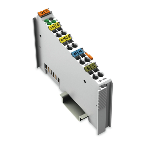
The AS-interface master module 750-655 is
used to integrate the AS-interface network into
the WAGO-I/O-SYSTEM 750.
The AS-interface master module 750-655
behaves as a master for the AS-interface and as
a slave for the field bus. It complies with the
new AS-interface specification 2.1. This means
that:
• up to 62 AS-interface slaves can be connected
to the master
• the transmission of analog values is integrated
within the masters
• all other functions of the new specification,
such as the evaluation of peripheral errors, are
also implemented
The SMLC’s PLC Configuration supports using
the 750-655 with any of the 750 Series Ethernet
bus couplers.
9/13/2007 Using the WAGO 750-655 AS-i Module with the SMLC 3
From the WAGO manual
for the 750-655.
Up to three 750-655
modules can be
connected to one bus
coupler.
IMPORTANT: You
must have SMLC
firmware version 2.4.2
or later to use the 750-
655 module!
9/13/2007 Using the WAGO 750-655 AS-i Module with the SMLC 4
The 750-655 can be
configured in several
different operating modes.
In each of these modes
various process image
sizes can be selected,
allowing access to
increasing numbers of
AS-i slaves.
The SMLC requires that
the 750-655 be configured
in operating Mode 1 -
permanently configured
mailbox.
The SMLC requires the use of Mode 1
9/13/2007 Using the WAGO 750-655 AS-i Module with the SMLC 5
While the 750-655 can be configured for
many different process image sizes the
SMLC supports a limited number of these.
In the SMLC’s PLC Configuration you can
select from the following Mode 1 possible
configurations:
24 byte process image, 6 byte mailbox
12 byte process image, 6 byte mailbox
12 byte process image, 0 byte mailbox
40 byte process image, 0 byte mailbox
48 byte process image, 12 byte mailbox
The 0 byte mailbox configurations only
support digital slaves. If you intend to use
analog slaves you need to select a
configuration with a non-zero length
mailbox.
The table at the right shows all of the
possible Mode 1 configurations. The SMLC
only supports those listed above!
9/13/2007 Using the WAGO 750-655 AS-i Module with the SMLC 6
In order to decide which configuration you should insert into the SMLC’s PLC Configuration consider how many
slave devices you intend to use and whether they are all digital or if you will have some analog devices.
If you are going to use analog device you must use one of the configuration that supports the mailbox.
If you are going to use all digital devices you can pick one of the configurations with a 0 byte mailbox. The
advantage of the 0 byte mailbox is that the AS-i module will take up less memory in the bus coupler’s process
image, allowing you to install more I/O modules. Remember that the bus coupler is limited to 255 bytes of
inputs and 255 bytes of outputs and a maximum of 64 modules.
For example: if you know that you will have less then 20 digital AS-i devices and no analog devices then
selecting the 12 byte process image with a 0 byte mailbox is sufficient.
The table below shows how many slave devices can be supported for a given configuration. 7A indicates 7 slaves
on the A bus. 31A/31B indicates 31 slaves on the A bus and 31 slaves on the B bus, etc.
9/13/2007 Using the WAGO 750-655 AS-i Module with the SMLC 7
In order to configure the 750-655 AS-i module and to assign the slave device IDs you need to use
the WAGO I/O Check software (759-302). Connect the WAGO programming cable (750-920) to the
bus coupler and to a free serial port on your computer.
NOTE: If the Ethernet cable is plugged into the bus coupler, unplug it. WAGO I/O Check will not allow
you to configure the bus coupler while the fieldbus is active!
9/13/2007 Using the WAGO 750-655 AS-i Module with the SMLC 8
Start WAGO-I/O-Check configure the I/O Check COM port using the Settings menu.
In this example the cable is connected to COM2.
9/13/2007 Using the WAGO 750-655 AS-i Module with the SMLC 9
Start WAGO-I/O-Check and click on the Node Configuration icon to read the current configuration. In
this example we only have the 750-655 AS-i module and a 750-600 end module connected to a 750-342.
9/13/2007 Using the WAGO 750-655 AS-i Module with the SMLC 10
Click on the Settings button to configure the process image and mailbox size. The default settings are
24 byte process image and 6 byte fixed mailbox. The SMLC supports this configuration and this selection
allows you to access up to 31 AS-i slaves.
The SMLC does not support the Overlapped Mailbox so do not check this.
If you change any of the settings click the Apply button to send the new configuration to the bus coupler.
9/13/2007 Using the WAGO 750-655 AS-i Module with the SMLC 11
Select the Direct Control mode
9/13/2007 Using the WAGO 750-655 AS-i Module with the SMLC 12
Click on the Process Data button to configure the AS-i network
9/13/2007 Using the WAGO 750-655 AS-i Module with the SMLC 13
The Master Configuration screen shows the current AS-i network and any connected slaves.
By selecting a slave you can monitor its inputs and toggle its outputs.
9/13/2007 Using the WAGO 750-655 AS-i Module with the SMLC 14
Suppose we want to change the address of Slave 1A to 2A. Check the Configuration Active (CA) box
and then enter the new address (2A) and click the Set button.
9/13/2007 Using the WAGO 750-655 AS-i Module with the SMLC 15
Note that the network view shows <Slave missing> for 1A and the Configuration OK LED is red. Click
on the Store Config button
9/13/2007 Using the WAGO 750-655 AS-i Module with the SMLC 16
Now the slave address has been re-assigned and the Configuration OK LED is green
9/13/2007 Using the WAGO 750-655 AS-i Module with the SMLC 17
Uncheck Configuration Active (CA) and close the window
9/13/2007 Using the WAGO 750-655 AS-i Module with the SMLC 18
Quite WAGO I/O Check, reconnect the Ethernet cable to the bus coupler and start CoDeSys.
Add a WAGO Ethernet bus coupler to your PLC Configuration and set the IP address.
In this example the WAGO
bus coupler’s IP Address is
192.168.1.12
9/13/2007 Using the WAGO 750-655 AS-i Module with the SMLC 19
Right click on the Fieldbus
Coupler in the SMLC’s PLC
Configuration and select Append
Sublement.
The menu expands to show all
available Wago modules. The
various configurations of the
750-655 AS-i modules that can
be selected.
9/13/2007 Using the WAGO 750-655 AS-i Module with the SMLC 20
For this example we will use the default
configuration of a 24 byte process image with a
6 byte mailbox.
The PLC Configuration tree now shows the AS-
i module with 24 input bytes and 24 output
bytes. The comment fields for each byte are
useful in determining what each byte is.
For our I/O what we are interested in are the
device IDs of the slaves on the AS-i network:
1A, 2A, 3A etc.
Each AS-i slave has 4 bits of inputs and 4 bits of
outputs available.

Other WAGO Control Unit manuals

WAGO 750-632 User manual

WAGO

WAGO 750-632 User manual

WAGO 750-523 User manual

WAGO

WAGO 750-523 User manual

WAGO 750-515 User manual

WAGO

WAGO 750-515 User manual

WAGO 750-439 User manual

WAGO

WAGO 750-439 User manual

WAGO I/O-SYSTEM 750 User manual

WAGO

WAGO I/O-SYSTEM 750 User manual
WAGO 750-495/040-00 Series User manual

WAGO

WAGO 750-495/040-00 Series User manual

WAGO 750-451 User manual

WAGO

WAGO 750-451 User manual

WAGO 751-5201 User manual

WAGO

WAGO 751-5201 User manual

WAGO 750-606/040-000 User manual

WAGO

WAGO 750-606/040-000 User manual

WAGO 750-563/040-000 User manual

WAGO

WAGO 750-563/040-000 User manual

WAGO 750-458 User manual

WAGO

WAGO 750-458 User manual

WAGO 750-489 User manual

WAGO

WAGO 750-489 User manual

WAGO 750-616/040-000 User manual

WAGO

WAGO 750-616/040-000 User manual

WAGO 750-439/040-000 User manual

WAGO

WAGO 750-439/040-000 User manual
WAGO I/O-SYSTEM 750 User manual

WAGO

WAGO I/O-SYSTEM 750 User manual

WAGO 750-363/0040-0000 User manual

WAGO

WAGO 750-363/0040-0000 User manual

WAGO WAGO-I/O-SYSTEM 750 Series User manual

WAGO

WAGO WAGO-I/O-SYSTEM 750 Series User manual

WAGO 750-535 User manual

WAGO

WAGO 750-535 User manual

WAGO WAGO-I/O-SYSTEM 750-506 User manual

WAGO

WAGO WAGO-I/O-SYSTEM 750-506 User manual

WAGO 753-646 User manual

WAGO

WAGO 753-646 User manual

WAGO 750-494 Series User manual

WAGO

WAGO 750-494 Series User manual
WAGO 750-652/040-000 User manual

WAGO

WAGO 750-652/040-000 User manual

WAGO 751-3501 User manual

WAGO

WAGO 751-3501 User manual

WAGO 750-450 User manual

WAGO

WAGO 750-450 User manual

Popular Control Unit manuals by other brands

Honeywell PRO4200 installation guide

Honeywell

Honeywell PRO4200 installation guide

Puls YRM2.DIODE installation manual

Puls

Puls YRM2.DIODE installation manual

Dometic GROUP WAECO MagicSpeed MS-BE3 Installation and operating manual

Dometic GROUP

Dometic GROUP WAECO MagicSpeed MS-BE3 Installation and operating manual

Kramer TBUS-5i installation instructions

Kramer

Kramer TBUS-5i installation instructions

DSC Misterhouse PC5401 installation instructions

DSC

DSC Misterhouse PC5401 installation instructions

Rockford Fosgate iPod Interface Module Installation & operation

Rockford Fosgate

Rockford Fosgate iPod Interface Module Installation & operation

ELPRO 905U-K user manual

ELPRO

ELPRO 905U-K user manual

Yamaha ACD1 Reference manual

Yamaha

Yamaha ACD1 Reference manual

INAZUMA WebCSA Series operating instructions

INAZUMA

INAZUMA WebCSA Series operating instructions

HEROSE 0651X operating instructions

HEROSE

HEROSE 0651X operating instructions

CRE Technology UNIGEN Plus Technical documentation

CRE Technology

CRE Technology UNIGEN Plus Technical documentation

Toshiba IK-4KE instruction manual

Toshiba

Toshiba IK-4KE instruction manual

bonitron M3699 Reference manual

bonitron

bonitron M3699 Reference manual

LOVATO ELECTRIC EXP10 16 instruction manual

LOVATO ELECTRIC

LOVATO ELECTRIC EXP10 16 instruction manual

Allen-Bradley ControlLogix DeviceNet 1756-DNB installation instructions

Allen-Bradley

Allen-Bradley ControlLogix DeviceNet 1756-DNB installation instructions

MTT MS3766 user manual

MTT

MTT MS3766 user manual

Bailey Infi 90 NICL01 Instruction

Bailey

Bailey Infi 90 NICL01 Instruction

maxon motor EPOS4 EtherCAT Card Hardware reference

maxon motor

maxon motor EPOS4 EtherCAT Card Hardware reference

manuals.online logo
manuals.online logoBrands
  • About & Mission
  • Contact us
  • Privacy Policy
  • Terms and Conditions

Copyright 2025 Manuals.Online. All Rights Reserved.