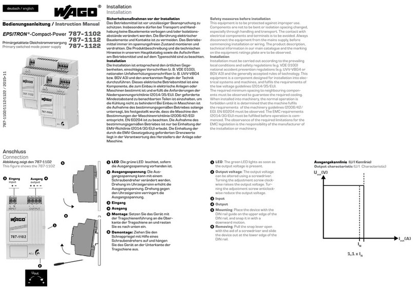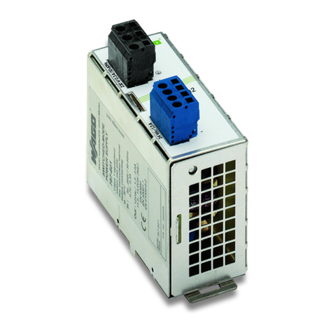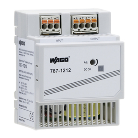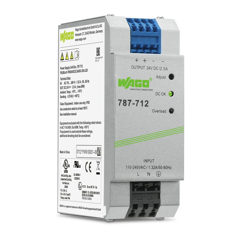
EPSITRON® COMPACT Power Table of Contents 3
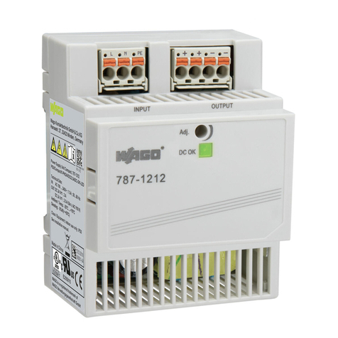
787-1202 / -1212 / -1216 / -1226 EPSITRON® COMPACT Power
Manual
Version 1.0.0
Pos: 5 /D ok ume nt ati on al lg em ein /V erz eic h nis se /I nhal ts ver z eich ni s - Ü b ers chri f t oG und Ver zei ch nis @ 3\mod_1219151230875_21.docx@21063 @ @ 1
Table of Contents
1Notes about this Documentation................................................................. 5
1.1 Validity of this Documentation................................................................. 5
1.2 Copyright................................................................................................... 5
1.3 Symbols..................................................................................................... 6
1.4 Number Notation....................................................................................... 8
1.5 Font Conventions ...................................................................................... 8
2Important Notes ........................................................................................... 9
2.1 Legal Bases ............................................................................................... 9
2.1.1 Subject to Changes ............................................................................... 9
2.1.2 Personnel Qualification ........................................................................ 9
2.1.3 Use of the 787 Series in Compliance with Underlying Provisions ...... 9
2.1.4 Technical State of the Devices ........................................................... 10
2.2 Safety Advice (Precautions).................................................................... 11
2.2.1 Special Notes for Use in Accordance to EN 60335 ........................... 13
2.2.2 Special Notes on Use as a DIN-Rail Built-in Installation Device...... 14
3Device Description ..................................................................................... 15
3.1 View ........................................................................................................ 16
3.2 Type Plate................................................................................................ 19
3.3 Connectors............................................................................................... 20
3.3.1 Connectors.......................................................................................... 20
3.3.1.1 Connector Input Side ..................................................................... 21
3.3.1.2 Connector Output Side .................................................................. 21
3.4 Display Elements .................................................................................... 22
3.5 Operating Elements................................................................................. 23
3.5.1 Potentiometer...................................................................................... 23
3.5.2 Slide Switch (only with 787-1226)..................................................... 23
3.6 Technical Data ........................................................................................ 24
3.7 Approvals ................................................................................................ 30
3.8 Standards and Guidelines ........................................................................ 31
3.9 Other Information on Standards and Directives...................................... 33
4Mounting..................................................................................................... 34
4.1 Mounting Positions ................................................................................. 34
4.2 DIN 35 Rail ............................................................................................. 35
4.2.1 DIN-Rail Mounting ............................................................................ 35
4.2.2 Removal from DIN-Rail..................................................................... 36
4.3 Screw Mounting ...................................................................................... 37
5Connect Devices ......................................................................................... 39
5.1 Connectors............................................................................................... 39
5.1.1 Connecting Conductors ...................................................................... 39
5.1.1.1 Connecting Using a Tool ............................................................... 40
5.1.1.2 Directly Inserting Conductors........................................................ 40
5.1.2 WAGO picoMAX® Connectors........................................................... 40
5.1.2.1 Status at delivery............................................................................ 40
5.1.2.2 Removing the Female Connector .................................................. 41
5.1.2.2.1 Removing the Female Connector without Wiring .................... 41
