Wahlberg 241 User manual

WWW.WAHLBERG.DK AXEL GRUHNS VEJ 3
TELEPHONE: +45 86 18 14 20 8270 HØJBJERG
EMAIL: sales@wahlberg.dk DENMARK
Winch 10
Item No 241
User Manual

241.805.012 2 Date: 2017-10-24
Safety Information
The following symbols are used to identify important safety information on the product
an in this manual:
This product is for professional use only. It is not for household use.
This product presents risks for severe injury or death due to fire hazards, electric
shock, and falls.
Read this manual before installing, powering or servicing the winch; follow the safety
precautions listed below and observe all warnings in this manual and printed on the
winch. If you have questions about how to operate the winch safely, please contact
you Wahlberg Motion Design supplier or Wahlberg Motion Design.
PROTECTION FROM ELECTRIC SHOCK
−Disconnect the winch from AC power before removing or installing any cover or
part and not when in use.
−Always ground (earth) the winch electrically.
−Use only a source of AC power that complies with local building and electrical
codes and has both overload and ground-fault (earth-fault) protection.
−Before using the winch, check that all power distribution equipment and cables
are in perfect condition and rated for the current requirements of all connected
devices.
−Power input throughput cables must be rated 20 A minimum, have three
conductors 1.5 mm2(AWG16) minimum conductor size and an outer cable
diameter of 5-15 mm (0.2-0.6 inch). Cables must be hard usage type (SJT or
equivalent) and heat-resistant to 90°C (194°F) minimum. In the EU the cables
must be <HAR> or equivalent.
−Use only Neutrik powerCON TRUE1 NAC3FX-W cable connectors to connect to
power input sockets. Use only Neutrik powerCON TRUE1 NAC3MX-W cable
connectors to connect to power throughput sockets.
−Assembly power supply cables following the instructions in this manual only (see
page 13).

241.805.012 3 Date: 2017-10-24
−Isolate the winch from power immediately if the power plug or any seal, cover,
cable, or other component is damaged, defective, deformed, wet, or showing
signs of overheating. Do not reapply power until repairs have been completed.
−Do not expose the winch to rain or moisture.
−Refer any service operation not described in this manual to a qualified
technician.
PROTECTION FROM BURNS AND FIRE
−Do not operate the winch if the ambient temperature (Ta) exceeds 40°C (104°F).
−The exterior of the winch becomes warm during use. Avoid contact by persons
and materials. Allow the winch to cool for at least 10 minutes before handling.
−Do not modify the winch in any way not described in this manual.
−Install only genuine Wahlberg parts.
PROTECTION FROM INJURY
−Fasten the winch securely to a fixed surface, rig, or structure when in use. The
winch is not portable when installed.
−Ensure that any supporting structure and/or hardware can hold at least 10 times
the weight of all the devices including their load.
−If suspending from a rigging structure, fasten the winch using the supplied
Manfrotto slim coupler and M12 bolt, nut, and washers supplied with the winch
according to the manual, see page 11.
−Always install the winch as described in this manual. If the winch is installed in a
location where it may cause injury or damage if it falls, install as described in
page 11.
−If possible, allow enough clearance beneath the winch so it cannot cause any
danger to personnel beneath it.
−Check that all external cobblers and rigging hardware are securely fastened.
−Block access below the work area and from a stable platform whenever installing,
servicing or moving the winch.
−Do not operate the winch with missing or damaged covers, shields, or wire.
−Do not use the winch over the head of people
−Do not use the winch to lift people or animals.
−Only use the winch to lift static loads.
Inspection
points
Intact wire
Broken wire
Before each use
−Check that the winch is safely and correctly installed/mounted.
−Inspect the entire length of the wire rope for bends, damage
and wear, cut cords, corrosion and abuse.
−Inspect the wire ferrule crimp and thimble for damage, wear,
corrosion or abuse.
−Secure that the load is safely attached and weighs maximum 10
kg (22.0 lb).
−Check all limit switches
−Check the slack detection device
Warning! Do not use the winch if any damage or error is found!

241.805.012 4 Date: 2017-10-24
Disposing of this product
Wahlberg Motion Design products are supplied in compliance with Directive
2002/96/EC of the European Parliament and of the Council of the European
Union on WEEE (Waste Electrical and Electronic Equipment), as amended
by Directive 2003/108/EC, where applicable.
Help preserve the environment! Ensure that this product is recycled at the
end of its life. Your supplier can give details of local arrangements for the
disposal of Wahlberg Motion Design products.

241.805.012 5 Date: 2017-10-24
Index
SAFETY INFORMATION 2
INDEX 4
TECHNICAL SPECIFICATIONS 6
DRAWING 7
INTRODUCTION 8
PACKAGE CONTENT .........................................................................................8
DESCRIPTION................................................................................................8
SAFETY FUNCTIONS .........................................................................................8
AREA OF USE................................................................................................9
USING FOR THE FIRST TIME..................................................................................9
TRANSPORT................................................................................................10
PHYSICAL INSTALLATION 11
FASTENING THE WINCH TO A FLAT SURFACE ................................................................11
MOUNTING THE WINCH ON A TRUSS ........................................................................11
MOUNTING THE LOAD ......................................................................................12
AC POWER 13
POWER CABLES AND POWER PLUG ..........................................................................13
INSTALLING A POWER INPUT CONNECTOR ON A POWER CABLE...............................................13
DATA LINK 14
TIPS FOR RELIABLE DATA TRANSMISSION ....................................................................14
CONNECTING THE DMX ....................................................................................14
SET UP 15
BLOCK DIAGRAM ...........................................................................................15
COUNTERBALANCE -SLACK WIRE ..........................................................................15
CONNECTIONS .............................................................................................15
EMERGENCY STOP..........................................................................................16
MODE SETTING............................................................................................16
DMX ADDRESS SETTING ..................................................................................18
MANUAL RESET.............................................................................................20
POSITIONING...............................................................................................20
RE-CALIBRATING OVERLOAD................................................................................21
SYNCHRONIZED MOVEMENTS OF MULTIPLE WINCHES.........................................................21
CONTROLLING THE SOFT TOP AND BOTTOM LIMITS .......................................................22
SERVICE AND MAINTENANCE 23
PARTS .....................................................................................................23
MAINTENANCE PLAN........................................................................................24
CHECKLIST.................................................................................................24
ON-SITE SERVICE...........................................................................................25
LIFE OF THE WIRE..........................................................................................25
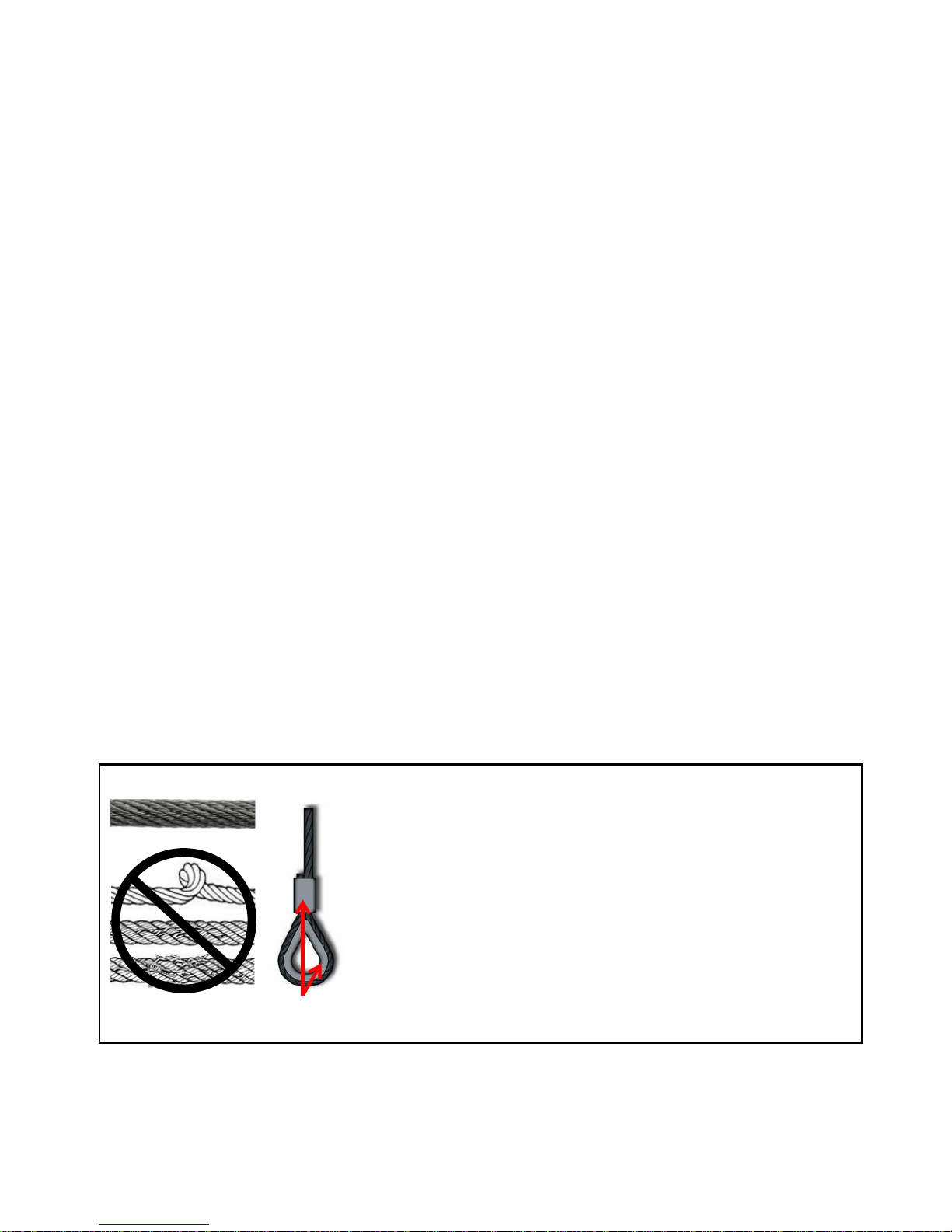
WIRE DEFECT ..............................................................................................26
WIRE DISCARD CRITERIA....................................................................................27
CHANGING WIRE ...........................................................................................28
APPLYING WIRE ............................................................................................33
POWER DEFECT ............................................................................................33
APPENDIX 1 34
APPENDIX 2 35
APPENDIX 3 37
WINCH 10 - CHEAT SHEET 38

241.805.012 6 Date: 2017-10-24
Technical specifications
Model: Winch 10
Item no.: 241
Dimensions (L×H×W): 205 × 224 × 148 mm / 8.1 × 8.8 × 5.8 in
(Without mounting clamp)
Power supply: 230 V AC 50 Hz (optional 120V/60Hz).
Power consumption: Max 120 Watt
Power inlet/outlet: Neutrik powerCON TRUE1 NAC3PX (F/M)
DMX control signal: DMX 512 1990 + DMX512A / 7 channels used.
DMX connection: 5 pole XLR, In & link
Lifting height: 10 m (33 ft.)
Lifting capacity: 10 kg (22 lb)
Lifting speed: Variable, 5-30 cm/s (2-11.8 in/s)
Snap hook: 8 mm (5/16 in) galvanized steel
Capability of overload test: Yes, at 125% of maximum load.
Wire fleet angle: None
Minimum load: 0.4 kg (0.88 lb)
Noise emission: ~55 dB (max measured noise at 1 m/3.3 ft.)
Weight: 5.2 kg (11.5 lb)
Mounting clamp: Slim eye coupler 50 mm (2 in)
Motor: 24 V DC, 28.9 Watt, IP30
Lifting wire specifications:
Lifting wire: 2 mm (5/64 in) 7x7 galv. steel wire (EN 12385-4)
Minimum breaking load (wire): 280 kg (2750 N / 618 lb)
Wire safety factor: minimum 10
Maximum expected wire lifetime:
−At 2.5 kg (5.5 lb) load Up to 80,000 cycles running up and down.
−At 5.0 kg (11.0 lb) load Up to 20,000 cycles running up and down.
−At 10 kg (22.0 lb) load Up to 15,000 cycles running up and down.

241.805.012 7 Date: 2017-10-24
Drawing
More detailed drawings and from more angles can be found in Appendix 1 on page 34.

241.805.012 8 Date: 2017-10-24
Introduction
Thank you for selecting the winch 10, a DMX controlled winch from Wahlberg Motion
Design. Before using the winch for the first time, please read this manual carefully.
Failure in handling can cause injury of persons and/or damage the winch.
Package content
1× Winch 10
1× Manfrotto Slim coupler
1× Mounting bolt, nut, and washers (M12) for slim coupler mounting
1× Neutrik PowerCon NAC3FX-W female plug for power cable
1× 8 mm snap hook
1x User manual
1x Cheat sheet
Description
Winch 10 is a small winch for stage use, mainly for use in theatres, shows, and
concerts. It lifts props and small set pieces in and out of the stage sphere at a
maximum load of 10 kg up and down. Lifting height is 10 meters, and the lifting speed
is from 5cm/s to 30 cm/s.
The winch is controlled by the standard DMX controlling signal, so a normal lighting
desk can be used to control the movement, programmed as normal light.
For a low number of winches, a standard lighting desk can be used, but when many
winches are used, more advanced desks should be used to maintain easy control of the
units.
The Winch 10 uses 7 channels of the DMX-line, and they control the position, speed,
limits, and reset functions.
The Winch 10 has an advanced internal positioning system with 16 bit, used for finding
the position desired by the operator. With a 16 bit positioning channel (ch1 and ch2)
the operator set the desired position, and the winch will run to this position, with the
speed applied on the speed channel (ch3).
With channel 4 and 5 it is possible to set the soft TOP and BOTTOM limits of the winch,
adjusting its span of motion.
Channel 6 and 7 is used for resetting the winch, when powering up.
Multiple winches are easily daisy chained with power in-out and DMX in-Out, allowing
to create advanced and dynamic movements with 100’s of winches working together in
the same installation.
Safety functions
The control system ensures that the motor only is powered when:
•The control signal is reliable.
•The position and speed control is on.
•The motor position is calculated after which a PID regulator calculates the motor
speed and distance.
•No overload.

241.805.012 9 Date: 2017-10-24
Winch 10 should only be operated by an experienced DMX-controlled-lighting-desk-
operator.
The lighting desk has to be programmed according to the manual, so the winch will
stop when the speed is put to 0 %. It is also possible for the user to stop the winch by
disconnecting it from the main. After power failure the start position of the winch
needs to be reset before the winch can function again.
Manual operation of the winch is only intended for mounting, service, and tests.
Area of use
For indoor use only!
Caution! To reduce the risk of electric shock or injury: use indoors only
Caution! To reduce the risk of electric shock, do not expose to rain: store indoors!
The winch is intended for indoor use only. It is designed for lifting and lowering
material at the weight and speed stated in "Technical specifications" on page 6. Any
other use of the winch may result in a risk of injury of persons or equipment damage.
Exceeding the load rating may cause failure of the equipment.
Use only approved rigging connectors to secure the load to the wire and do not wrap
the wire around the load as this will damage the wire and result in a risk of injury of
persons or equipment damage.
Do not modify the winch. For any modification of your winch, contact Wahlberg.
It is the customer's sole responsibility to comply with any relevant local laws,
regulatory requirements, and restrictions, concerning the use of the winch.
Using for the first time
Important! The Winch 10 must be protected from environmental factors such as
physical shocks and vibration during storage.
Warning! Read “Safety Information” on page 2 before installing, powering,
operating, or servicing the winch. Before applying power to the winch:
−Check the Wahlberg Motion Design website at www.wahlberg.dk for the most
recent documentation and technical information about the winch 10. Wahlberg
user manual revisions are identified by the revision number in the bottom of each
page.
−Carefully review the “Safety Instructions” on page 2.
−Check that the local AC mains power source is within the winch power voltage
and frequency ranges.
−See “Power cables and power plug” on page 2. Install a Neutrik powerCON TRUE1
NAC3FX-W power input connector on a suitable power cable. If using the power
from a mains power outlet, install a suitable power plug on the power cable.

241.805.012 10 Date: 2017-10-24
Transport
Important! The Winch 10 must be protected from environmental factors such as
physical shocks and vibration during transportation.
Before transport, it is important to roll the wire of the winch up till the hard TOP limit
so a maximum of 5 cm (1.9 inch) remains out of the winch. If the wire is loose it may
jump off the wire wheel during transport and cause damage to the winch.
Use only the original packaging, flight case, or pallet frame for protecting the winch
during transport. Contact Wahlberg for enquiries regarding flight cases or pallet
frames.

241.805.012 11 Date: 2017-10-24
Physical installation
Warning! The winch must be either fastened to a flat surface such as a roof, or
clamped to a truss or similar structure in such a way that the wire exit points
downwards. Do not apply power to the Winch if it is not securely fastened.
Warning! If fastening the winch to a flat surface, the supporting surface must be
hard and flat. Fasten the winch securely.
Warning! If mounting the winch on a truss, use only the supplied rigging clamp and
M12 bolt. The clamp must be screwed into the central hole in the winch’s mounting
bracket using the supplied M12 washers and M12 locking-nut.
Fastening the winch to a flat surface
The Winch 10 can be fastened to flat surface such as a roof. Check that the surface
can support at least 10 times the weight of all winches and equipment to be installed
on it.
Mounting the winch on a truss
The Winch 10 can be clamped to a truss or similar rigging structure.
To clamp a Winch 10 to a truss:
1. Check that the rigging clamp is undamaged and that the rigging structure can
support at least 10 times the combined weight of all winches and equipment to
be installed on it.
2. Use the supplied rigging clamp or contact Wahlberg Motion Design for a
replacement.
3. Fasten the clamp to the winch with the supplied M12 bolt, nut, and washers in
the hole in the mounting clamp of the winch.
4. Block access under the work area. Working from a stable platform, hang the
winch on the truss with the wire downwards. Tighten the rigging clamp.

241.805.012 12 Date: 2017-10-24
Mounting the load
Attention! The load must be mounted on the wire in a way to insure that the load
never can run into the winch.
The load can be mounted using the supplied loading hook or any other hooks designed
for lifting. Ensure that the loading hook has a minimum breaking load of at least 100
kg.

241.805.012 13 Date: 2017-10-24
AC power
Warning! Read “Safety Information” on page 2 before connecting the winch to AC
mains power.
Warning! For protection from electric shock, the winch must be grounded
(earthed). The power distribution circuit must be equipped with a fuse or circuit
breaker and ground-fault (earth-fault) protection.
Warning! Socket outlets or external power switches used to supply the winch with
power must be located near the winch and easily accessible so that the winch can
easily be disconnected from power.
Warning! Check that the voltage range specified on the winch’s serial number label
matches the local AC mains power voltage before applying power to the winch. Do
not apply AC mains power to the winch at any other voltage than that specified on
the winch’s serial number label.
Power cables and power plug
The Winch 10 requires a power input cable with a Neutrik powerCON TRUE1 NAC3FX-W
cable connector for AC mains power input. The cable must meet the requirements
listed under “Protection from electric shock” on page 2.
Wahlberg Motion Design can supply the PowerCON input connector without a cable.
If you install a power plug on the power cable, install a grounding-type (earthed) plug
that is rated 20 A. Follow the plug manufacturer’s instructions. Table 1 shows standard
wire color-coding schemes and some possible pin identification schemes; if pins are not
clearly identified, or if you have any doubts about proper installation, consult a
qualified electrician.
Table 1 - Colour guide
Wire Colour Conductor Symbol Screw (US)
Brown Live L Yellow or brass
Blue Neutral N Silver
Yellow/green Ground (earth)
or
Green
Installing a power input connector on a power cable
To install a Neutrik powerCON TRUE1 NAC3FX-W input connector on a power
Cable, follow the original Neutrik instructions in Appendix 2.

241.805.012 14 Date: 2017-10-24
Data link
A DMX 512 data link is required in order to control the winch via DMX. The Winch 10
has 5-pin XLR connectors for DMX data input and output. The pin-out on all connectors
is pin 1 = shield, pin 2 = (-), and pin 3 = (+). Pins 4 and 5 in the 5-pin XLR connectors
are not used in the Winch 10 but are available for possible additional data signals as
required by the DMX512-A standard.
The Winch 10 is subject to the common limit of 32 devices per daisy-chained link. Note
that if independent control of a winch is required, it must have its own DMX channels.
Winches that are required to behave identically can share the same DMX channels. To
add more winches or groups of winches when the above limit is reached, add a DMX
universe and another daisy-chained link.
Tips for reliable data transmission
Use shielded twisted-pair cable designed for RS-485 devices: standard microphone
cable cannot transmit control data reliably over long runs. AWG24 cable is suitable
for runs up to 100 meters (328 ft.).
Never split a DMX line without using an opto-isolated RS-485 splitter/amplifier.
Terminate the link by installing a termination plug in the output socket of the last
winch. The termination plug, which is a male XLR plug with a 120 Ohm, 0.25 Watt
resistor soldered between pins 2 and 3, “soaks up” the control signal so it does not
reflect and cause interference. If a splitter is used, terminate each branch of the
link.
Connecting the DMX
To connect the Winch 10 to data:
1. Connect the DMX data output from the DMX controller to the Winch 10’s male 5-
pin XLR DMX input connector (DMX 512 IN).
2. Connect the DMX output of the winch to the DMX input of the next winch and
continue connecting winches output to input (DMX 512 OUT).
3. Terminate the last winch on the link with a 120 Ohm resistor.
The DMX lamp is the green led, next to the DMX-selectors.
−Glows constantly: DMX connection is correct.
−Flashes: DMX signal is missing or wrongly connected.

241.805.012 15 Date: 2017-10-24
Set up
Warning! Read “Safety Information” on page 2 before installing, powering,
operating, or servicing the Winch 10.
Warning! Before running the winch, it is important to put a counterbalance on the
wire. This is necessary, as the slack detection switch otherwise will be activated
and stop the winch.
Warning! Only experienced DMX users should operate the winch. Contact Wahlberg
for further information and education on DMX protocol.
Block diagram
A block diagram of the control system can be found in Appendix 3.
Counterbalance - Slack Wire
To ensure proper and tight winding of the wire on the drum, the winch is equipped
with a slack detections device, that stops the motor if the wire is loose or wire slack
detected.
Therefore, when the winch is mounted, ensure that the winch has some kind of
counterweight attached to the wire hook, if not, the winch will not work properly, and
will not lower down.
Connections
The winch has 4 plugs. At the top there are 2 DMX plugs, one for connecting DMX in
and one for daisy chaining the DMX connection to other devices.
Below there is a power connection plug for POWER in, and one plug that can be used to
daisy chain the power connection between multiple devices.
Below those plugs are the voltage selector and the fuse. It is important that the
voltage selector has been set to the appropriate voltage before power is applied to the
winch.

241.805.012 16 Date: 2017-10-24
Emergency stop
There is no dedicated emergency stop for this winch. The winch is controlled from a
lightning desk, where it should always be set up with a button that sets the speed of
the winch in operation to 0%.
Normally lighting desks have a “blackout” button that sets all signals to 0% and this
will also cause the winch to stop.
MODE setting
The MODE setting allows you to operate the winch in different ways. Each MODE
setting has a given function. Each mode gives an opportunity for different operational
settings of the winch. The MODE is selected using the MODE selector on the Winch.
The winch needs to be reset, before the positioning MODE is possible. The winch can
be reset manually or automatically. The winch must be reset each time its power
supply has been disconnected.
Read the passage about controlling the soft TOP- and BOTTOM limits, to explore and
setup the winch for your own particular needs.
Warning! Only operate the winch when there is a clear view to the winch and area
beneath it.
Warning! Before running the winch, ensure that the area beneath the winch is
cleared to avoid risk of injury.
Warning! When resetting the winch in MODE 2, it is important to decrease the
speed, as the snap hook is closing in on the motor-house, otherwise the wire and
winch can be damaged.
Warning! MODE 7 and MODE 8 is only for service and tests!

241.805.012 17 Date: 2017-10-24
MODE
Function
Description
Note
0 Neutral Mode The motor is not powered and the winch does not move.
1 Positioning
AUTO reset The winch resets automatically and thereby also sets the
soft TOP limit automatically.
The winch runs up until the snap hook reaches the motor-
house and stops. Because of this, the soft TOP limit in this
MODE will always be at the motor-house.
To start the automatic resetting, speed must be added on
the speed-channel (DMX channel 3).
When the winch has been reset, it is possible to use it in
positioning mode.
2 Positioning
MANUAL reset The winch is manually reset on the DMX channels 6 or 7.
The soft TOP limit is, because of this, also set manually,
which makes it possible to decide the position of the soft
TOP limit.
It is highly recommended to set the soft TOP limit at the
motor-house. When the winch has been reset, it is possible
to use it in positioning mode.
Warning! When
resetting in MODE
2, decrease the
speed, as the
load is closing in
on the winch,
otherwise the
lifting cable and
winch can be
damaged
3,4,5,6 No function assigned The winch stops
7 Manual run up
(no DMX needed)
The winch runs up with the speed set on the DMX-selectors.
This function can be used as a test-function or in association
with on- and off-applying of wire.
E.g. Set the winch to MODE 7 and the DMX address to 100,
for a slow movement, or set the DMX address to 500 for fast
movement.
Warning! Only for
service and tests!
8 Manual run up
(no DMX needed)
The winch runs down with the speed set on the DMX-
selectors.
This function can be used as a test-function or in association
with on- and off-applying of wire.
E.g. Set the winch to MODE 8 and the DMX address to 100,
for a slow movement, or set the DMX address to 500 for fast
movement.
Warning! Only for
service and tests!
9 Re-calibrating
overload See page 21 Warning! Only for
service and tests!
Table 2 - Overview of MODE functions

241.805.012 18 Date: 2017-10-24
DMX ADDRESS setting
The DMX address, also known as the start channel, is the first channel used to receive
instructions from the controller. For independent control, each winch must be assigned
its own control channels.
The DMX address is configured using the three DMX ADDRESS selectors on the winch.
The selected DMX address states from which channels, on the lighting desk, the winch
is controlled. The DMX address can be selected from 1 – 505. The Winch 10 uses 7 DMX
channels.
DMX
channel
Function
Description
1 Position rough This channel controls the position of the winch, with the speed (DMX channel 3).
This rough position works together with the fine position (DMX channel 2).
The rough position and the fine position are multiplied in to a 16 bit channel.
The rough position is the MSB.
2 Position fine This channel controls the position of the winch, with the speed set on DMX
channel 3.
This fine position works together with the rough position (DMX channel 1).
The fine position and the rough position are multiplied in to a 16 bit channel.
The fine position is the LSB.
3 Speed This channel controls the speed and defines the maximum speed of the winch.
The winch runs with the set max speed, but slows down as closing in on the
wanted position.
This channel also works as a main brake; the motor does not run unless the
channel is set above 0%.
The speed-channel can also be used to make soft and slow movements or fast
and sudden movements.

241.805.012 19 Date: 2017-10-24
4 Set soft TOP limit This channel controls the maximum top travelling height of the winch. When the
winch has been reset and the soft TOP limit thereby has been declared, it is
possible, by adjusting this channel, to change how high the winch may run in
proportion to the soft TOP limit. So the top travelling height for the winch is
changed.
0% declares the maximal top travelling height, which means it runs all the way
up to the soft TOP limit.
100% declares the minimal top travelling, which means it is as far from the soft
TOP limit as possible.
By adjusting this channel the positioning run from 0 - 100% will be within this
new parameter. The top travelling height can be changed as needed, without
resetting the winch’s soft TOP limit.
5 Set soft BOTTOM
limit The channel controls the soft BOTTOM limit of the winch. When the winch has
been reset and the soft TOP limit thereby has been declared, it is possible, by
adjusting this channel, to change how low the winch may run in proportion to
the soft BOTTOM limit. So the soft BOTTOM limit for the winch is changed.
0% declares the maximal bottom travelling height, which means it, runs all the
way down to the soft BOTTOM limit.
100% declares the minimal bottom travelling, which means it is as far from the
soft BOTTOM limit as possible.
By adjusting this channel the positioning run from 0 - 100% will be within this
new parameter. The bottom travelling height can be changed as needed,
without resetting the winch soft TOP limit.
6 Find soft TOP
limit, moving UP The channel is used to manually finding the soft TOP limit. The channel controls
the speed from 0-100%.
The winch starts to run up when channel 6 is set above 0%. When the winch
reaches the wanted soft TOP limit, the speed must be set to 0 %, so that the
motor stops.
The soft TOP limit of the winch is then set to the position the winch stopped in.
The soft TOP limit should always be near by the motor-house. See more details
in the passage controlling the soft TOP and BOTTOM limits.
Attention! The positioning run in MODE 2 works only, when the winch has
been reset.
7 Moving down The winch starts to run down when the speed is set above 0 %. This can be used
to manually move the winch down without using positioning.
This does not change the soft TOP limit.
Table 3 - Overview of DMX addresses

241.805.012 20 Date: 2017-10-24
Manual reset
When the winch is ready, the first thing to do is to reset it. This is done manually in
MODE 2 on DMX channel 6.
Reset example:
−The DMX channel 6 is set to 30% →the winch starts to roll up the wire.
−When the snap hook approaches the motor house reduce the speed by reducing
the DMX channel 6 input. High speed can damage the winch and wire.
−Let it run until the snap hook, at the end of the wire, reaches the motor-house.
The winch is now reset and the soft TOP limit is at the build-in motor-house top (10 cm
below).
If you want to have a lower soft TOP limit, simply just set the DMX channel 6 to 0% and
the place where the winch stops is your new soft TOP limit.
The soft BOTTOM limit is set in the same way, just using DMX channel 7 instead.
Positioning
When the winch has been reset and the soft TOP limit is set, it is possible to use it for
positioning run.
The green LED next to the MODE selector indicates by
−Fast flashing The winch needs to be reset, before it can be used.
−Slow flashing The winch’s load is moving towards the set position
−Steady light The set position has been reached and the motor has stopped.
The position is set on the DMX channel 1 and 2, which controls the rough-and fine-
position. Where 100 % is the soft TOP limit and 0 % is the soft BOTTOM limit.
The speed is set on the DMX channel 3, where 100 % is the fastest and 0 % is the
slowest.
The winch does not run unless the DMX channel 3 is set above zero, and DMX channel
3, therefore also works as a main brake.
This manual suits for next models
1
Table of contents
Other Wahlberg Lifting System manuals
Popular Lifting System manuals by other brands

Dragon Wholesaling
Dragon Wholesaling LF750 user manual

twin busch
twin busch TW M-02 Installation, operation and maintanance

Ravaglioli
Ravaglioli RAV1140 Translation of the original instructions

rav
rav KPS306HER Translation of the original instructions

Tecnimoem
Tecnimoem Powerlift Up 1 user manual

EZ-ACCESS
EZ-ACCESS Modular Ramp Assembly manual