Wakespeed Offshore WS100/12 User manual

Thank you for purchasing Wakespeed Offshore’s Model WS100/12 Multi-
Stage Voltage Regulator. Designed by Michael Frost, one of the pioneers of
smart, multi-stage battery charging systems, the Wakespeed WS100/12
voltage regulator provides optimal care for your batteries, when used in
conjunction with a P-type, externally regulated alternator.
The WS100/12 was designed specically to provide the user with an ex-
tremely simple interface — only two adjustments are required to deliver
tailored charging to your batteries. A convenient ve-position rotating
switch enables the user to select one of ve programs based on battery
type: standard ooded/gel, standard AGM, Carbon Foam, deep cycle
ooded and high-density AGM/TPPL.
In addition to the selectable programs for battery type, the WS100/12
provides the ability to adjust the maximum regulator eld output, making
it possible to reduce alternator horsepower load to the engine and belt.
Four settings are available: 100% (no eld reduction), 90%, 75% and
50% eld output.
The WS100/12 can be used alone, or in conjunction with optional WS-
100-ATS and WS-100-BTS alternator and battery temperature sensors.
With the temperature sensors installed, the WS100/12 can monitor and
respond to changes in ambient battery temperatures and reduce charging
output if the alternator temperature exceeds safe operating temperatures.
WS100/12 Product Manual
Page 1

REGULATOR WIRING
The Wakespeed WS100/12 is provided with
a 5-wire harness, which provides wiring
connections required for proper voltage
regulator operation. Wires include Red
(Power), Black (Ground), Blue (Field), Brown
(Ignition) and Orange (Dash Lamp). Wiring
identication and suggested mounting
locations are as follows:
RED (POWER) WIRE —
The WS100/12 Power Wire provides DC
current to support regulator functions
and to provide eld current to control
alternator excitation (eld) output – as well
as providing the regulator with sensing
voltage. The Power Wire must be fused at
10 amps. An ATC-type fuse holder and 10A
ATC fuse are included with the regulator, and
must be installed at the source of power (at the
alternator or battery end of the wiring harness).
Possible connection locations for the RED
Power Wire include:
1. The positive output post of the alternator
(recommended).
2. The positive post of the battery being
charged.
3. If a diode-type battery isolator is
used, the RED power wire must be
installed on the output side of the
isolator, on the post connected to
the larger battery bank.
WS100/12 Product Manual
Regulator Wiring
Page 2

WS100/12 Product Manual
Regulator Wiring
BLACK (GROUND) WIRE —
The WS100/12 Ground Wire provides a connection between the voltage
regulator and system ground. Possible connection locations for the
BLACK Ground Wire include:
1. The ground post of the alternator (recommended).
2. The ground post of the battery being charged.
BROWN (IGNITION) WIRE —
The WS100/12 Ignition Wire provides a switched source of DC system
voltage which acts as the ON/OFF switch for the voltage regulator.
Possible connection locations for the BROWN Ignition Wire include:
1. The ON side of the vessel’s ignition switch. In most cases, a switched
source of ignition voltage will already be established at your engine’s
alternator. Refer to your engine manual to identify your alternator’s
ignition wire. The wire should provide zero volts when the ignition
is off and the engine is not running, and system voltage whenthe
ignition switch is on and the engine is running (recommended).
2. The ON side of an oil pressure switch.
BLUE (FIELD) WIRE —
The BLUE eld wire in the regulator’s wiring harness provides eld current
to the alternator’s positive brush, which enables the regulator to control
excitation and alternator output. The BLUE eld wire is connected to the
eld terminal of an externally regulated P-type alternator.
If your alternator is not designed for external voltage regulation (i.e., an
internally-regulated alternator) it will be necessary to modify the alternator
to provide access to the alternator’s positive brush.
In some cases, this will require that the alternator must be opened up
to disable the internal regulator and diode trio, and a direct pathway be
created between the positive brush and a terminal on the outside of the
alternator that’s isolated from the alternator’s grounded frame. This can
be a difcult process.
We strongly recommend using a qualied alternator shop for any alternator
modications, including conversion to external regulation.
Page 3

WS100/12 Product Manual
Regulator Wiring
ORANGE (DASH LAMP) WIRE —
The ORANGE Dash Lamp circuit is designed to provide a source of
ground to complete a circuit at a warning light or audible alarm if one
of the following conditions exists: low system voltage (alternator is not
charging properly), high system voltage (alternator is charging above safe
voltage), high alternator temperature (requires alternator temperature
sensor), high battery temperature (potential thermal runaway at batteries).
The Dash Lamp wire can be connected to the negative (ground) side of a
user-installed warning lamp or audible alarm.
Page 4
OPTIONAL TEMPERATURE SENSOR CABLES
When used in conjunction with its optional temperature sensor cables,
the WS100 can use ambient temperatures at the batteries and at the
alternator to provide additional safety and charging efciency. Connection
for temperature sensor cables is provided via built-in RJ45 terminals at
the bottom of the regulator.
WS100-BTS-KIT — Battery Temperature Sensor Cable (BLUE)
WS100-ATS-KIT — Alternator Temperature Sensor Cable (GREEN)

WS100/12 Product Manual
Regulator Wiring
BLUE (BATTERY) CABLE —
The WS100/12 Battery Temperature Sensor cable connects the regulator
to the battery via a temperature sensor IC that’s mounted in a battery
lug which can be connected directly to the battery’s ground post. The
Battery Temperature Sensor includes a 15-foot (BLUE) Cat5e data cable
which connects to the Bat Temp RJ45 connector. When connected, the
Battery Temperature Sensor will allow the regulator to make adjustments
to charging voltage based on the ambient temperature of the batteries
being charged.
When connected to a multiple battery bank,
the Battery Temperature Sensor lug should be
located on the ground terminal closest to the
center of the battery bank. In addition to enabling
the regulator to adjust for ambient battery
temperature, the Battery Temperature Sensor
will enable the regulator to shut down if battery
temperature exceeds safe levels (>125°F).
NOTE: Do not install or remove battery or regulator temperature
sensor cable while regulator is activated.
GREEN (ALTERNATOR) CABLE —
The WS100/12 Alternator Temperature Sensor cable enables the voltage
regulator to reduce eld (excitation) output to the alternator if temperatures
at the alternator case exceed recommended temperature levels.
The lug containing the temperature sensor IC can be mounted on a rear
case bolt, or to the ground post of the alternator. An RJ45 keystone jack
located at the bottom of the regulator is provided to connect the 7-foot
(GREEN) Cat5e data cable to the regulator.
NOTE: Do not install or remove battery or regulator temperature
sensor cable while regulator is activated.
Page 5

Page 6
REGULATOR PROGRAMMING
Programming the Wakespeed WS100/12
is remarkably simple. Five programs,
listed below, can be selected by rotating
the (GREEN) color-coded knob marked
Program Select, located to the right of
center at the top of the regulator.
As the knob is turned clockwise or counter-
clockwise, the the lights marked one
through ve on the regulator’s label will light
up, indicating your program selection.
Note: the regulator must be turned on
prior to programming. When turned on, the
regulator will display the #1 green light, and
the number of the existing program setting
at start up. Program Select choices are as
follows:
Program #1 Standard Flooded/Gel —
Designed to properly charge standard (thin plate) ooded and gel
battery types. See chart on Page 6 for specic charging voltage values.
Program #1 is indicated by the far left green light marked “1”.
Program #2 Standard Absorbed Glass Mat —
Program #2 provides proper charging voltages for many common AGM-
type batteries. See chart on Page 6 for specic charging voltage values.
Program #2 is indicated when #1 and #2 green lights are illuminated.
lights are illuminated.
NOTE: To provide protection from accidental program changes, any
adjustments will only be implemented by turning off the ignition
and disconnecting the regulator from its power source after
changes have been made. The new program will initiate with the
subsequent engine start up.
WS100/12 Product Manual
Regulator Programming
PROGRAM ADJUSTMENT KNOB

Page 7
WS100/12 Product Manual
Regulator Programming
Program #3 Carbon Foam AGM —
Program #3 provides proper charging voltages carbon foam AGM
batteries (such as those marketed under the Firey® brand). See chart on
the last page for specic charging voltage values. Program #3 is indicated
when #1 and #3 green lights are illuminated.
Program #4 Deep Cycle Flooded —
Program #4 provides proper charging voltages for traditional deep-cycle
(thick plate) ooded batteries. See chart on the last page for specic
charging voltage values. Program #4 is indicated when #1 and #4 green
lights are illuminated.
Program #5 High Density Absorbed Glass Mat/TPPL —
Program #5 provides proper charging voltages for high-density AGM-
type and TPPL (Thin Plate, Pure Lead) batteries. See chart on Page 6 for
specic charging voltage values. Program #2 is indicated when #1 and #2
green lights are illuminated.
Time and voltage settings for each battery program are detailed at the
end of this instruction book. Be sure to consult your battery manufacturer
for recommendations prior to programming the regulator for your battery
type.
NOTE: To provide protection from accidental program changes, any
adjustments will only be implemented by turning off the ignition and
disconnecting the regulator from its power source after changes
have been made. The new program will initiate with the subsequent
engine start up.

WS100/12 Product Manual
Field Limit Programming
Page 8
FIELD LIMIT ADJUSTMENT
The Wakespeed WS100/12 provides
four levels of eld output control to allow
the user to de-rate the alternator to limit
engine horsepower load.
Controlled by the (RED) color-coded
knob labeled Field Limit to the left of
center at the top of the regulator, the
eld output can be adjusted by turning
thumbscrew clockwise or counter-
clockwise.
Output levels are broken down by
percentages of maximum eld output
provided by the regulator. Limits will be
indicated as follows:
1. 100% Field — Indicated by no
RED lights on the regulator, next to
codes indicated by A, B, or C on the
regulator’s label.
2. 90% Field — Indicated by the RED light illuminated by the letter A
on the regulator’s label.
3. 75% Field — Indicated by the RED light illuminated by the letter B
on the regulator’s label.
4. 50% Field — Indicated by the RED light illuminated by the letter C
on the regulator’s label.
NOTE: Adjustments to the Field Limit can be made “on the y”
and will immediately result in a decrease or increase to the value
selected.
Wakespeed recommends setting the eld limit at 90% to provide
protection against saturation alternator output.

WS100/12 Product Manual
Regulator Operation
Page 9
USING THE WAKESPEED WS100 REGULATOR
Once the WS100 regulator is properly wired to the alternator and
congured for your battery type, the regulator is ready to begin charging
your batteries. Following a short delay, the regulator will begin to ramp
up charging voltage to a bulk target voltage that’s determined by your
charging prole selection.
Once the regulator reaches bulk target voltage, the regulator will continue
to hold at target until the eld pulse width falls below its target level, and
the regulator will advance to the acceptance target voltage (typically two-
tenths of a volt below bulk target voltage). The regulator will continue
to charge at acceptance target voltage until the eld pulse width drops
below minimum target, at which point, the regulator will advance to oat
voltage.
While at target voltage for oat, the regulator will monitor the eld pulse
width. If the maximum oat pulse width cannot maintain the target voltage
for oat charging, the regulator will return to acceptance charging voltage.
During extended engine operation and under varying battery loads, the
voltage may cycle between charge modes multiple times.
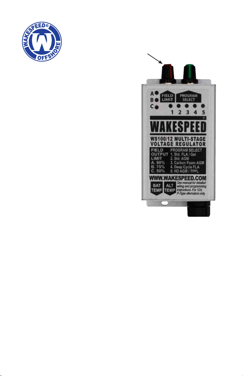
OPERATIONAL DISPLAY
During normal operation, the regulator will display a combination of green
lights in positions marked one through ve, indicating the progress of the
charge program. A combination of lights, as described below will indicate
charging activity status. Codes are as follows:
1. #1 Green Light — Indicates regulator is turned on.
2. #1 & #2 Green Lights — Indicates regulator is in bulk charge mode.
3. #1 & #3 Green Lights — Indicates regulator is in absorption charge
mode.
4. #1 & #4 Green Lights — Indicates regulator is in oat charge mode.
5. #5 Green Light — Indicates Dash Lamp mode is active. May be
active as a result of low system voltage, high system voltage, high
alternator temperature (>225°F) or high battery temperature (>125°F).

WS100/12 Product Manual
Data & Program Values
Page 10
Model.......................................WS100/12
Description.............Multi-Stage Regulator
System Voltage............................. 12VDC
Excitation..............Positive Field (P-Type)
Processor ......................... Microchip 8 Bit
Preset Programs.....................................5
Field Output Levels.................................4
Alternator Temperature Sensing....... Yes*
Battery Temperature Sensing ........... Yes*
Baseline Battery Temperature ........ 25°C
Enclosure......... Anodized Aluminum Alloy
Dimensions................. 4-7/8” x 2-5/8” x 1”
Display.....................Color-coded LED (8)
Circuit Protection ........Conformal Coating
Regulator Program Values
Prog.
#Battery Type Bulk
Volts
Acceptance
Volts
Float
Volts
Fixed
Time
Flex
Time
(Min)
Float
Time
(Max)
Temp. Comp.
mV/°C
1 Std.FLA/Gel 14.1 13.9 13.4 18m 18m 120m 24
2Std. AGM 14.38 14.18 13.4 18m 18m 120m 24
3 Carbon Foam 14.4 14.2 13.4 18m 18m 120m 24
4Deep Cycle
FLA 14.6 14.4 13.5 18m 18m 120m 30
5HD AGM/
TPPL 14.7 14.5 13.6 18m 18m 120m 24
REGULATOR DATA
* Requires optional Battery and Alternator Temperature Sensor Cables

WS100/12 Product Manual
Limited Product Warranty
TWO-YEAR LIMITED PRODUCT WARRANTY
Wakespeed® warrants the original purchaser the product is free from
any defects in material or workmanship for a period of two years from
the original date of purchase. If any such defect is discovered within the
warranty period, Wakespeed will repair or replace the product free of
charge, subject to verication of the defect or malfunction upon delivery
or shipping prepaid to Thomason Jones Company/Wakespeed, PO Box
1541, Anacortes, WA 98221.
Defects or physical damage resulting from abuse, neglect, accident,
improper repair, alteration, modication, or unreasonable use of the
products are not covered under warranty. Returned products showing
evidence of tampering and/or unapproved access to internal components
will not be supported under warranty.
Wakespeed cannot warrranty Broken cases, parts damaged by re, water,
freezing, collision, theft, explosion, rust, corrosion, damaged cables or
wiring harnesses, or items damaged in shipment in route to Wakespeed
Warranty Services for repair. Thomason Jones Company/Wakespeed
assumes no responsibility for consequential damage or loss or expense
arising from these products or any labor required for service or repair.
Wakespeed will not repair or be held responsible for any product sent
without proper identication and return address or Return Authorization
number clearly marked on the package. You must include proof of date
and place of purchase (photocopy of purchase invoice) or we cannot
be responsible for repairs or replacement. In order to expedite warranty
claims, Wakespeed requires that a Return Authorization is completed
prior to returning a defective product for repair.
If factory service is required, contact Wakespeed Warranty Service
Monday through Thursday, 8:30 AM to 3:30 PM, (PST) at 360-299-1231,
defective part or product is to be supplied free of charge upon delivery
of the defective product to Wakespeed Warranty Service. Customer is
responsible for all return transportation charges and any air, international
or rush delivery expense.
Page 11

Page 12
NOTES:
For more information, visit www.wakespeed.com
Or call Wakespeed Support at 360-299-1231
Wakespeed Offshore
PO Box 1541
Anacortes, WA 98221
Table of contents
Popular Boating Equipment manuals by other brands

EZ Dock
EZ Dock 204010 installation instructions

NORTHROP GRUMMAN
NORTHROP GRUMMAN NAVIGAT X MK 1 Operation, installation and service manual

ZF
ZF 311 Series manual

Raritan
Raritan RUDDERMASTER Installation and maintenance instructions

Seafloor
Seafloor EchoBoat ASV manual

Hobie
Hobie 30115 installation instructions