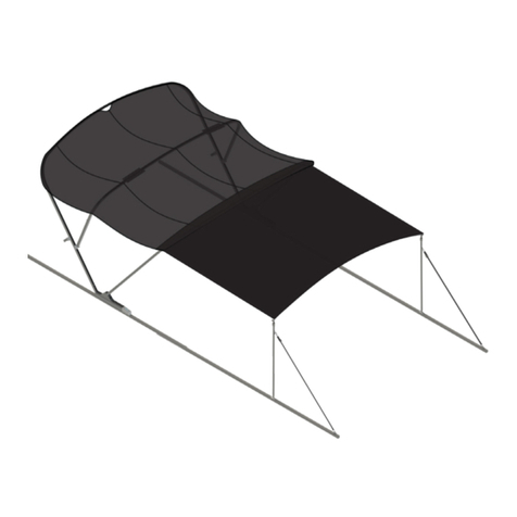
Lippert SureShade Power Bimini User manual

SureShade®
Power Bimini
OEM INSTALLATION MANUAL

Rev: 07.06.21 Page 2 CCD-0003657
TABLE OF CONTENTS
Introduction 2
Safety 3
Resources Required 4
Preparation 4
Installation 4
Installing Actuators 4
Wiring Actuators 9
Mounting Actuators 10
Installing Stand-os 11
Installing Helm Switch 13
Installing Front Strut 13
Final Assembly 15
Wiring Diagram 17
Operation 17
Helm-mounted Control Switch 17
RF Remote Control Installation - Optional 18
Resources Required 18
RF Receiver Installation 18
RF Remote Control Operation - Optional 20
Key Fob Remote 20
Notes 21
Introduction
The SureShade Power Bimini is an electric actuator-driven Bimini top powered by a 12V DC source,
controlled by a helm-mounted momentary switch or an optional RF remote control system.
For information on the assembly or individual components of this product, please visit:
https://support.lci1.com/marine-products/ .
Note: Images used in this document are for reference only when assembling, installing and/or operating
this product. Actual appearance of provided and/or purchased parts and assemblies may differ.

Rev: 07.06.21 Page 3 CCD-0003657
The "WARNING" symbol above is a sign that a procedure has a safety risk involved and may cause
death or serious personal injury and/or severe product or property damage if not performed safely
and within the parameters set forth in this manual.
Failure to follow instructions provided in this manual may result in death, serious personal injury
and/or severe product and property damage, including voiding of the component warranty.
The “CAUTION” symbol above is a sign that a safety risk is involved and may cause personal injury
and/or product or property damage if not safely adhered to and within the parameters set forth
in this manual.
Safety
Read and understand all instructions before installing or operating this product. Adhere to all safety labels.
This manual provides general instructions. Many variables can change the circumstances of the instructions,
i.e., the degree of difficulty, operation and ability of the individual performing the instructions. This
manual cannot begin to plot out instructions for every possibility, but provides the general instructions,
as necessary, for effectively interfacing with the device, product or system. Failure to correctly follow the
provided instructions may result in death, serious personal injury, severe product and/or property damage,
including voiding of the LCI limited warranty.
Always wear eye protection when performing service, maintenance or installation procedures.
Other safety equipment to consider would be hearing protection, gloves and possibly a full face
shield, depending on the nature of the task.
All electrical wiring harnesses shall be loomed and secured to prevent possible damage and
installed in accordance with the latest ABYC (American Boat and Yacht Council) electrical standards,
E11 and S31

Rev: 07.06.21 Page 4 CCD-0003657
Resources Required
• 1-2 persons, depending on task
• Pencil
• Cordless or electric drill or screw gun
• 3/8" drill bit
• 3/8" nut-driver bit
• 1/2" drill bit
• Appropriate Phillips drive bit
• Appropriate drive bit
• Tape measure
• 1/2" wrench
• Phillips screwdrivers (x2)
• Wire cutter/stripper
• Wire crimper
• 5/32" hex wrench
• Multimeter
Preparation
If working with a pre-wired boat frame/railing, connect actuators to the existing harness.
Refer to Wiring Diagram.
If boat frame/railing is not pre-wired, run the wire from the actuator to the helm. Since each boat is
configured differently, there are a few options for wiring the actuators to the helm.
• Option 1 — Inside the boat’s rear frame.
• Option 2 — Along the bottom side of the boat’s rear frame.
• Option 3 — Along the top or side of the boat’s rear frame.
When establishing the proper placement and width of the strut/actuator assemblies on the frame/railings,
it would help to have the stand-off installed to make sure they land squarely on the railing when the bimini
top is fully closed.
Installation
Note: The following installation instructions may be rearranged and performed in the order that best
accommodates the OEM's best shop practice.
Installing Actuators
When installing the actuators (Fig. 1) onto the boat's frame/railing, make sure:
• The actuators are mounted square, level and plum to one another (Fig. 2).
• No actuator is mounted more than 1/4" ahead of the other (Fig. 2).
• Wires are run in a manner that will prevent them from being pinched under the actuators.
• Actuator minimum voltage is 11V DC when under load.
Identify which actuator is going to be mounted onto the boat's port railing and which actuator will be
mounted onto the boat's starboard railing.
Note: There is a port and starboard rear strut assembly (Fig. 3). Each strut's mounting holes must be facing
up (Fig. 3).

Rev: 07.06.21 Page 5 CCD-0003657
Fig. 1
Bimini Frame
Actuator Assemblies
Rear Starboard Bimini
Frame Assembly
Rear Port Bimini
Frame Assembly
Frame Assembly
Mounting Holes
Fig. 2
Fig. 3
Rear Frame
Assemblies
Port
Actuator
Starboard
Actuator
Make
Parallel
1/4" Max Offset
Align Actuators Even

Rev: 07.06.21 Page 6 CCD-0003657
1. Slide a rear strut assembly (Fig. 4A) over each actuator's rear receiver handle (Fig. 4B).
Fig. 4
Fig. 5
2. Secure each rear strut assembly using 1/4" hex cap screws (Fig. 5A), then tighten using a 5/32" hex
wrench (Fig. 5B).
A
B
A
B

Rev: 07.06.21 Page 7 CCD-0003657
Fig. 6
4. Insert a center bow (Fig. 7A) approximately 1" into the left and right rear struts of the rear
strutassemblies.
5. Insert a center bow (Fig. 7B) approximately 1" into the left and right middle struts of the rear
strutassemblies.
3. Place each rear strut/actuator assembly onto the boat's frame/railing (Fig. 6).
Note: Proper rear strut assembly positioning is generally determined by locating the assembly so that
when the top is down, the struts are just behind the rear seats. Too far forward and the top will
interfere with rear seating; while too far aft will provide less shade to the front of the boat.
Fig. 7
Starboard
Port
B
Middle Strut
A
Rear Strut
Frame/Railing
Frame/Railing

Rev: 07.06.21 Page 8 CCD-0003657
6. Adjust the width spacing between the rear strut/actuator assemblies (Fig. 8, Dim A) until the bimini
width matches the boat’s rear frame/railing width (Fig. 8, Dim B).
Fig. 8
7. Move the port and starboard actuator assemblies (Fig. 2) forward and aft until the actuators are in-line
with each other.
A. Make sure the actuators are mounted square, level and plum to one another.
B. Make sure no actuator is mounted more than 1/4" ahead of the other (Fig. 2).
8. After properly positioning each strut/actuator assembly, use a pencil to make a line across the frame/
railing in front of the actuators (Fig. 9). Set actuator assemblies aside.
Strut/Actuator
Assembly
Frame/Railing
Dim A
Dim B
Fig. 9

Rev: 07.06.21 Page 9 CCD-0003657
9. For each strut/actuator assembly, put a tape measure on the pencil line made at the front of the
actuator (Fig. 10). Measure back 1/2" and 16 1/2" and mark these locations on the frame/railing with a
pencil (Fig. 10).
10. At each pencil mark, find the center of the railing's width (Fig. 10) then drill a through-hole, two places
(Fig. 10A) using a 3/8" bit. These holes need to go all of the way through the railing tube.
Note: Use care when drilling through a pre-wired boat frame/railing. If necessary, drill through one wall of
the tube, then inspect for wires to make sure they are out of the way.
Wiring Actuators
Fig. 10
1/2"
16 1/2"
Front of
Actuator
Center of
Railing Width
A
A
All electrical wiring harnesses shall be loomed and secured to prevent possible damage and
installed in accordance with the latest ABYC (American Boat and Yacht Council) electrical standards,
E11 and S31
If working with a pre-wired boat frame/railing, actuators can be connected to the existing harness.
Refer to Wiring Diagram.
If boat frame/railing is not pre-wired, run the wire from the actuator to the helm. Since each boat is
configured differently, there are a few options for wiring the actuators to the helm.
• Option 1 — Inside the boat’s rear frame.
• Option 2 — Along the bottom side of the boat’s rear frame.
• Option 3 — Along the top or side of the boat’s rear frame.
A new hole will need to be drilled into the frame/railing to run the wires from the actuator to the helm.
Locate this new hole by looking at where the wires exit the actuator and then transfer this location to the
boat’s frame/railing and drill the hole according to the following, selected Option.
Option 1 - inside of frame
For each actuator:
1. Drill a third hole half way through the top of the boat’s rear frame/rail to accept the actuator wire.
2. Snake the wires through the inside of the rear frame/railing until they exit under the boat.
3. Then run the wires to the underside of the helm and fish it up into the helm.
Some boat frames/railings may be pre-wired. Drilling through a pre-wired frame/railing may nick or
cut electrical wires, resulting in a damaged and/or unusable electrical harness.

Rev: 07.06.21 Page 10 CCD-0003657
Option 2 - bottom of frame
For each actuator:
1. Drill a third hole all the way through the boat’s rear frame/rail to accept the actuator wire.
2. Run the wire under the top frame using fastener-mount zip ties (not included) to support the wire,
then run the wires to the helm.
Note: Direct entry into the helm from the top frame is normally possible.
Option 3 - top or side of frame
For each actuator:
1. Bolt down the actuator. Refer to the Mounting Actuators section.
Note: Make sure wires are run in a manner that will prevent them from being pinched under the actuators.
2. Use fastener-mount zip ties (not included) to run the wire along the top or side of the boat frame/
railing and into the helm.
Mounting Actuators
1. Place the previously removed actuator assemblies on top of the frame/railing so that the actuators'
threaded mounting holes align with the drilled holes in the frame/railing.
2. For each actuator, assemble 5/16" flat washers (Fig. 11A) onto 5/16" x 1 3/4" bolts (Fig. 11B).
Fig. 11
B
A
Fig. 12
A
A
3. From the underside of the frame/railing, insert each assembled bolt into each through-hole (Fig. 12A),
engaging the threaded holes of the actuators.
4. Loosely tighten the bolt to the frame/railing.

Rev: 07.06.21 Page 11 CCD-0003657
5. Adjust the width spacing between the rear strut/actuator assemblies (step 6 of the Installing Actuator's
section and Fig. 8) until the bimini width matches the boat’s rear frame/railing width.
Note: When installed, each stand-off leg should rest as near the center as possible of the frame's siderail.
6. Use a 1/2" wrench to fasten down each rear strut/actuator assembly.
Installing Stand-offs
1. Position one of the H-brackets (Fig. 13A) on one of the rear strut assemblies 1/2" minimum behind the
middle strut's H-bracket (Fig. 13B)towards the rear of the strutand over a straight, flat area of the
frame's side railing.
Note: The final position of the rear strut H-bracket must NOT interfere with the operation of the bimini top
with the boot installed.
2. Using an electric drill with a 3/8" nut-driver, fasten the H-bracket to the strut assembly with a 1/4" self-
tapping screw (Fig. 14A).
A. Install two nylon bushings (Fig. 14B) into the pre-drilled holes of the H-bracket.
Fig. 13
1/2" Min
B
A
Rear Strut
Assembly
Fig. 14
AB
H-bracket

Rev: 07.06.21 Page 12 CCD-0003657
Fig. 15
B. Align pre-drilled holes in stand-off leg (Fig. 15A) with holes in the nylon bushings (Fig. 15B).
Note: Stand-off leg has a slight miter that should angle towards the end of the rear strut assembly.
C. Insert a Phillips nut (Fig. 15C) through one side of the H-bracket and into the bushing.
D. Insert a Phillips screw (Fig. 15D) into the other side of the H-bracket and bushing, then engage the
Phillips nut.
A
B
Mitered End
of Stand-off
C
D
After installation, leg should angle in this direction.
E. Tighten Phillips screw into the Phillips nut using two Phillips screwdrivers (Fig. 16).
3. Repeat steps 1 and 2 to install the second stand-off.
Fig. 16

Rev: 07.06.21 Page 13 CCD-0003657
Do NOT power actuators to the full open position without canvas installed. Damage may occur.
Installing Helm Switch
Note: A helm switch and RF Remote Control are provided, but both do not need to be installed for the
system to operate. If the helm switch and the RF Remote Control are both installed, refer to the
wiring diagram in that section.
Refer to the Wiring Diagram section for the following electrical connections:
1. Locate where on the helm the control switch will be mounted and drill 1/2" hole.
2. Trim excess wire length from the harness. Save excess wire for later use.
3. Connect the white wire from each actuator to one side of the switch.
4. Connect the dark blue wires to the other side of the switch.
5. Use previously trimmed excess wire (step 2) to connect the positive and negative battery leads and the
breaker as shown in the Wiring Diagram.
Installing Front Strut
Note: To make installing the front strut assembly easier, use the helm switch to advance the actuator
receiver handle into an acceptable position.
Note: Starboard and port front struts are identified by their mounting holes. Mounting holes must face up
with the bowed portion of the strut curving inward toward the inside of the boat.
1. Slide the starboard front strut (Fig. 17A) over the starboard-mounted actuator receiver
handle(Fig.17B).
2. Insert the center bow (Fig. 18A).
3. Insert the port front strut (Fig. 19A) over the center bow, then over the port-mounted actuator
receiverhandle.
Fig. 17
Starboard
Front Strut
A
B
C
Note: Rear and middle center bows not shown for clarity.

Rev: 07.06.21 Page 14 CCD-0003657
Fig. 18
A
Middle Strut
Center Bow
Rear Strut
Center Bow
Starboard
Front Strut
Fig. 19
A
Front Strut
Center Bow
Port Middle
Strut
Port Rear Strut
4. Secure starboard and port front struts using 1/4" socket hex cap screws (Fig. 17C). Tighten hex screws
with 5/32" hex wrench.

Rev: 07.06.21 Page 15 CCD-0003657
Final Assembly
1. Use a cordless or electric drill or screw gun and the #10 self-drilling Phillips screws (Fig. 18A) to fasten
all struts and bows together.
2. The middle strut assembly gets two screws as shown in figure 18B. Repeat this process for both sides
(port and starboard).
3. Complete the installation by attaching the canvas to the completed framework. The canvas end with
the notch goes on the rear strut.
Fig. 20
A
B
B
A
Front Strut
Middle Strut
Rear Strut
The canvas top has securing straps with female snaps located at the bow port and starboard corners and aft
port and starboard corners. Securing straps prevent undue billowing of the top when installing the boot.
Install securing straps as follows:
Note: The male snaps with self-tapping screws are provided by the bimini top (canvas) manufacturer. If
male snaps did not come with the canvas, contact the canvas manufacturer.
1. Starting at one canvas corner, tightly pull and wrap the securing strap around the bimini top
strut(Fig.21).
2. Mark the location of the female snap (Fig. 21) on the strut.
3. Repeat steps 1 and 2 for each securing strap.
4. Position the self-tapping screw of the male snap (Fig. 22A) over the previously marked location (step 2)
and use a drill or screw gun to install the male snap into the strut.
5. Wrap the securing strap around the strut as before (step 1) (Fig. 23) then snap the strap in-place.
6. Repeat steps 4 and 5 for each securing strap.

Rev: 07.06.21 Page 16 CCD-0003657
Canvas Top
Strut
Securing Strap
Female Snap
Fig. 21
A
Strut
Fig. 22
Fig. 23
Installed
Male Snap
Female Snap

Rev: 07.06.21 Page 17 CCD-0003657
Note red dot on
or near one motor
terminal.
3/16" flag terminal,
fully insulated,
4 req'd. DPDT reversing toggle switch,
Philmore #30 - 125.
1/4" spade terminal,
fully insulated,
4 req'd.
#10 insulated ring
terminal, 2 req'd.
6 Amp short stop breaker,
Bussman #121A06-A2M-HD.
Battery
Positive (+)
Battery
Ground ()
White Wire
Dark Blue Wire
Wiring Diagram
Operation
Fig. 24 Fig. 25
Before operating the power bimini top, thoroughly inspect the area around the entire bimini
assembly. Verify that nobody is in an area that will interfere with the motion of the bimini assembly.
Serious injury could result.
Helm-mounted Control Switch
Use the helm-mounted control switch to operate the power bimini top to verify successful installation.
1. If installed, remove the protective boot.
2. To extend the bimini top to full open position (Fig. 24), press and hold the helm switch until the
actuator motors turn off—do not release switch until both actuator motors turnoff.
3. To retract the bimini top to full down position (Fig. 25), press and hold the switch until motors turn
off—do not release switch until both actuator motors turnoff.
4. Install protective boot.

Rev: 07.06.21 Page 18 CCD-0003657
RF Remote Control Installation - Optional
The RF Remote Control is an optional control, but not required to be installed for the system tooperate.
Resources Required
• Cordless or electric drill or screw gun
• Appropriate drive bit
• Self-drilling wood screws
• 6 Amp short stop breaker
• DPDT reversing toggle switch (if not previously
installed)
• 3/16" insulated flag spade terminal
• 1/4" insulated spade terminal
• #10 insulated ring terminal
RF Receiver Installation
1. Select a protected location on the boat to mount the RF receiver (Fig. 26A), usually inside the helm.
2. Use an electric drill and four wood screws (not supplied) to secure the RF receiver.
Fig. 26
A
Mounting
Holes, 4X

Rev: 07.06.21 Page 19 CCD-0003657
3. Connect the battery and motor wires according to the schematic diagram shown in figure 27.
Note: If a helm-mounted switch is installed, connect it to the RF receiver as shown in the schematic (Fig. 27).
Fig. 27
Override Switch
Battery Ground (-)
Battery Positive (+)
Motor #1 White Wire
Motor #1 Dark Blue Wire
Motor #2 White Wire
Motor #2 Dark Blue Wire
Helm Switch Up
Helm Switch Down
Program Button
Status Light
NOTE RED DOT
ON OR NEAR
ONE MOTOR
TERMINAL
3/16" FLAG TERMINAL
FULLY INSULATED (4) REQ'D
DPDT REVERSING TOGGLE SWITCH
PHILMORE #30 - 125
BATTERY
POSITIVE (+)
1/4" SPADE TERMINAL
FULLY INSULATED
(3) REQUIRED
#10 INSULATED
RING TERMINAL
(2) REQUIRED
6 AMP SHORT STOP BREAKER
BUSSMAN #121A06-A2M-HD
Note: All wires to be 16 AWG.
BATTERY
GROUND (-)
AUX BAT
STATUS
LIGHT
PROGRAM
BUTTON
OVERRIDE
SWITCH

Rev: 07.06.21 Page 20 CCD-0003657
RF Remote Control Operation - Optional
Key Fob Remote
The up and down motion of the actuator is controlled by the key fob remote (Fig. 28). The Open (Fig. 28A)
and Close (Fig. 28B) buttons are latching, meaning once pressed, motion will automatically continue until
the commanded position is reached.
Note: While the bimini frame assembly is in motion, pressing either button will immediately stop all
motion. Always keep the key fob remote in your hand and be prepared to stop motion if needed.
Use the key fob remote to operate the power bimini top to verify successful installation.
1. If installed, remove the protective boot.
2. If necessary, slide the Safety Cover (Fig. 28) back to uncover the buttons.
3. To extend the bimini top to full open position (Fig. 24), press the Open button on the key fob until
motion begins and then release. Motion will continue and motors will automatically turn off.
4. After desired position is reached and motion has stopped, slide the Safety Cover up to cover buttons to
prevent any unintended transmissions.
5. To retract the bimini top to full down position (Fig. 25), slide the Safety Cover back to uncover
thebuttons.
6. Press the Open button on the key fob until motion begins and then release. Motion will continue and
motors will automatically turn off.
7. Install protective boot.
Fig. 28
Note: Key-fob shown in storage position.
Transmit LED
Safety
Cover Open
Safety
Cover Closed
B
A
Other manuals for SureShade Power Bimini
3
Table of contents
Other Lippert Boating Equipment manuals
Popular Boating Equipment manuals by other brands

Boston Whaler
Boston Whaler Pilot Seat Assembly instructions

Dock Doctors
Dock Doctors Paddle Products Beach Dolly Assembly instructions

WHEELEEZ
WHEELEEZ WZ1-BD instructions

Hobie
Hobie Mirage Compass instruction manual

Quick
Quick PRINCE DP2E Series user manual

Attwood
Attwood 66510 installation instructions

Wilderness Systems
Wilderness Systems AIRPRO 3D installation instructions

Vetus
Vetus BOW25 Series Installation Recommendations

M Jennings & Co
M Jennings & Co Hello Sailor owner's manual

MARIMEX
MARIMEX Star Instructions for use

Big Air
Big Air Predator Tower quick guide

CORRECT CRAFT
CORRECT CRAFT LINC PAN0RAY 2020 owner's manual