grielolk
•
• B
Move the MIX switch
Move Throttle stick to
the "2" position
neutral / center position
Left green LED light
i
f
•
•
ID Manual flight control
O
DEVO 10/F7 panel illustration
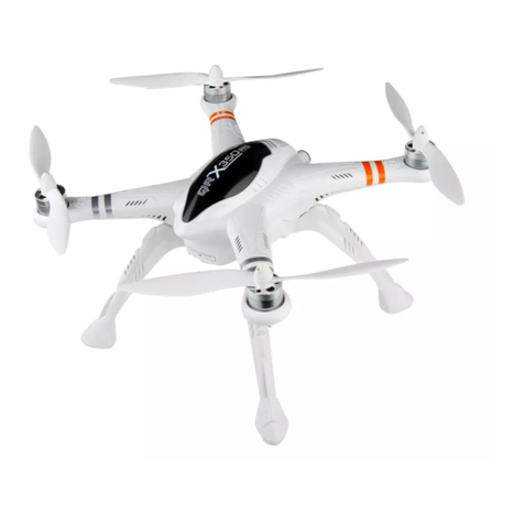
5.3 Connect the battery to the quad. Before powering the quad,
make sure the quad is level and sitting stable on the ground,
do not move the quad until the binding is finished.
•
•
6.5 Vertical direction (Head down)
rotation 360°(Rotate the aircraft,
from 0° to 90°, 180°, 270°, 360°,
all need to pause for 1 second.)
6.2 Forward& backward 360° rotation
(Rotate the aircraft, from 0° to 90°,
180°, 270°, 360°, all need to pause
for 1 second.)
6.3 Leftward & rightward 360° rotation
(Rotate the aircraft, from 0° to 90°,
180°, 270°, 360°, all need to pause
for 1 second.)
6.4 Horizon level 360° rotation
(Rotate the aircraft, from 0° to 90°,
180°, 270°, 360°, all need to pause
for 1 second.)
6.6 The left green LED flash quickly
till light out which means calibration
finished. Please reconnect the
aircraft power after calibration.
6.1 Enter compass calibration
•
Attention:
•
Compass Calibration
IMPORTANT:
Make sure the motors are locked before calibration (left indicator is NOT flashing). Factory default setting, is for the motors to be locked after the completed ID binding process. (For details on motor lock and unlock process see point 7 and 8)
After calibration, first time taking off, the aircraft may drift in the sky, please just ignore that, and meantime the system will do compass calibration automatically. After 3-5 minutes flight, please land the quadcopter on the ground and hold the motor in order to save calibration parameter.
•
•
fj
mii
IN"
Ire
Left green LED light
!,,
' A t
Mode
1(throttle
stick on the right)
NOTICE:
By default. After successful binding, the motors is locked.
Transmitter
Aircraft ('4
"is the nose direction)
Manual/ GPS Mode
Mode 1
Mode 2
T
AA
---.K .......
_,...
---.....„-:-.—... ...0.—...
..._
Throttle stick:
Controls the LIFT, of the aircraft.
Moving this stick up cause the aircraft climb
(or move up) the more you push on the stick,
the faster the aircraft climbs. The aircraft will
hover still in the air with the throttle stick at
the center position (50%) pushing up from
50% cause climb, moving the stick below
50% cause the quad to move down.
mmionwt.,_.,oka_k
.-
ikkilkiriMIIIIIiar
atl
IIIIIk
4(
----
P
11
. ,
7,
,_
1
1
,-
1
.„
.
1
s,
imill
,-)P4-4
,-
-
40
.,,
IN
= 11Elf
=
e
(2
b
'
rnisii
c,,?,
Ek
1,
‘1,
.%
Mode
1/Mode 2
M
i
f
A
Vii
1 N
k.
:4
1
"
4
.11
....,,,,
1
1
N
k
""
kki.
t
.::::::
1
P4
Rudder stick:
Controls the "YAW" axis = right-left turn.
Push the stick right for clickwise turn,
push the stick left for counter clockwise turn.
kt
ifC,
.
Inge-
re
iv
lak:::
:
4)
°
v
Mode
a
.:
.;.,.-al
r
.___
1
Mode 2
a
' Al.
g
A
%WkWI
P
MriA
do"
4#1140,
w
i
l
,
e
.
Ilio
..,;
*Air
•
N
-
6
-,
.,&*--
ul
'2)
,
4.".
..
1
'a
Elevator stick:
Controls the "PITCH" axis = forward and
backward motion of the aircraft.
Push the elevator stick up to move forwards,
push the elevator down to move backwards.
*
For typical forward flight, push the elevator
slightly forward to move forward.
a
;
4,1z,
-
„
-
.
1
:1
_PII
•
__, ,
4,147
4
r
--
; L II*
1 c>
'CI
,
1
II
o
i, 4&41,-
-
-
1
,..7_4!:4
r, , _
,,.1
Lv„,..7)),
_!,m
,
/4
--4,- -i]
-4,
Bo
---,
a 1
Jo
leo
k,
V.-
----
--1
a0
Mode
w
1
e,
_
1/Mode 2
' k1
101,/
!:4
_E
.--
i
A
.
Aileron stick:
Controls the "ROLL" axis = sideway motion.
Move the stick left for the quad to move left,
move the stick right for the quad to move right.
—
,...,..
.camo.
,,
..-- l'
,"
4
-
,
4 --....
-
—
M. ei nikAire
i
r,WAYAr
rg.,M
----
--
-
w:
----
raw--
-----
11 14"
1714!
IP
=
Bo
a
0
I
@
5
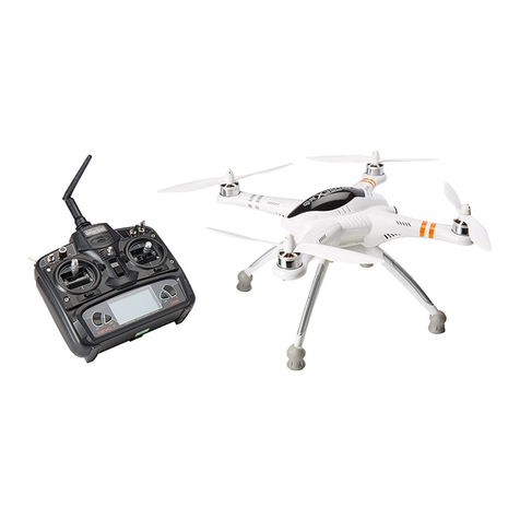
DEVO F7 radio
•
(1) GPS indicator lights. (Understand the mystical blinking of the right indicator light)
•
10
11
12
13
ng
Blinking
)s
5 times
Blinking
6 times
Blinking
7 times
Blinking
8 times
IMPORTANT:
For GPS flight mode, the RIGHT indicator light should be blinking 2 or more times, (indicating 7 or more satelites locked.)
•
•
•
Position Hold
•
REQUIREMENT:
SOLID GPS lock
GPS indicator should be blinking 2 times or more.
•
REQUIREMENT: IMU
must be calibrated, the throttle, elevator,
aileron and rudder trim should be at neutral positions.
•
Engage Position Hold while flying, in manual mode, move the
MIX to "1" position, (do not move other stick), this will cause the
QR X350PRO to enter position hold mode.
Keep the throttle stick at the neutral positing while in GPS hold mode.
If GPS signal is lost the aircraft will enter altitude hold mode.
•
Code binding
5.1 Connect the battery to the radio.
For safety: Make sure the battery
is fully charged before you fly!
5.2 Move the MIX and FMOD switches
to "0" position. Move the throttle to the
down position. Then turn on the radio.
O
Motor Lock
To Lock the motors.
Move the throttle stick to the lowest position,
and move the rudder stick to the far right.
The left green LED indicator light will go out when
the motors are locked.
TEST: if you gently push up on the throttle, the
motors will not start.
Mode 2(throttie stick on the left)
•
Motor Unlock
After Binding, move the throttle stick to the lowest position,
at the same time move the rudder stick to the far left side.
The left green LED indicator light will turn solid green, this
indicate that the motors are unlocked.
TEST: gently push the throttle up a little, the motors will spin.
NOTICE:
The MIX switch much be in Manual to unlock the motors.
It is mot possible to unlock the motors in GPS or RTH mode.
Note:
For safety, the motors will automatically lock after 10 seonds.
This means, if you do not start flying in 10 seconds, you have to unlock the motors again.
Left stick
THRO/RUDD stick
Mode 2
(Throttle stick
Right stick
ELEV/AILE stick
on the left)
Left trim
THRO trim
Right trim
ELEV trim
Left stick
ELEV/RUDD stick
Mode 1
Right stick
THRO/AILE stick
(Throttle stick
on the right)
Left trim
ELEV trim
Right trim
THRO trim
(1) Manual Mode
(2) Position Hold Mode
(3) One Key Go Home
•
0
MIX Switch to "0"
0
All
2.
00
MIX Switch to "2"
-"'
$
MIX Switch to "1"
AUX5(Control Gimble, Roll)
MIX(Control Mode Switch)
FMOD(IOC Switch)
Right trim
Right stick
'
A
FMOD
1 •
'V
FMOD
1
‘'
FMOD Switch to "0" or
"1": IOC
close
FMOD
•
—
AILE trim
AUX4(Control Gimble, Tilt)
GEAR(When user-defined
video, control video)
Left trim
Left stick
Power switch
RUDD trim
DEVO
10
radio
FMOD Switch to "2": IOC Active
AUX2(Control Gimble, Tilt)
GEAR(When user-defined
video, control video)
FMOD(IOC Switch)
Left trim
MIX(Control Mode Switch)
Left stick
Right stick
Right trim
AILE trim
Power switch
RUDD trim
•
One Key Go Home
•
REQUIREMENT:
SOLID GPS lock
GPS indicator should be blinking 2 times or more.
•
REQUIREMENT: IMU
must be calibrated, the throttle, elevator,
aileron and rudder trim should be at neutral positions.
•
One Key Return To Home (RTH)
While flying in manual mode, or in GPS position hold mode.
Engage RTH mode by moving the MIX switch to the "2" position
(don't move any other sticks)
IMPORTANT:
While in RTH mode, keep the throttle stick in the neutral position. The quad will land itself.
NOTE: you can resume control anytime by moving the MIX switch back to the "0" position.
IF you do so, make sure all stick are neutral, and that power is in the neutral (middle) position.
5.4 When the LEFT indicator light stop
flashing, the binding is successful.
-"li
d
'
}
(
-
to-
Model I
]
U .
?.0%
47.0%
18
'
4
Move the MIX switch
the "1" position
Move Throttle stick to
neutral / center position
GPS Satellites
9
<6
6
7
8
The right Green
LED status
No
blinking
Blinking
once
Blinking
2 times
Blinking
3 times
Blinki
4 tim
Mode
1(throttle
stick on the right)
Mode 2(throttie stick on the left)

