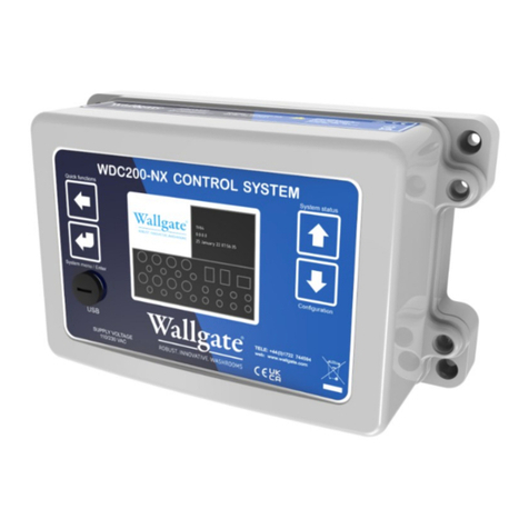
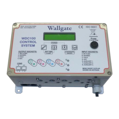
Wallgate WEX300 User manual

Product Manual
WEX300
Electrical Management Controller.
Original Instructions

2
WEX 300 Electrical Management.
Revision 2
•Appliance to be kept out of reach of children.
oChildren shall not play with the appliance.
oCleaning and user maintenance shall not be made by children
without supervision.
•This appliance can be used by persons with reduced physical,
sensory or mental capabilities or lack of experience and knowledge
if they have been given supervision or instruction concerning use of
the appliance in a safe way and understand the hazards involved.
•If the supply cord is damaged, it must be replaced by Wallgate, its
service agents or similarly qualified persons in order to avoid hazard.
AS 1172
Certificate No
23167
RCM Mark
Australia

3
WEX 300 Electrical Management.
Revision 2
Table of Contents
1. Disclaimer & Copyright Notice...............................................................................................4
2. Conventions ...........................................................................................................................4
2.1 Warning ..............................................................................................................................4
2.2 Note ....................................................................................................................................5
2.3 Numbered procedures .......................................................................................................5
2.4 Bullet lists............................................................................................................................5
2.5 Tick Bullet lists ....................................................................................................................5
2.6 Menu items.........................................................................................................................5
3Installation and Commissioning .........................................................................................5
3.1 Package Contents ...............................................................................................................5
3.2 Advice on attaching the unit ..............................................................................................6
4Product Summary...............................................................................................................6
5Product Specification..........................................................................................................7
5.1 Supply.........................................................................................................................7
5.2 Digital Inputs..............................................................................................................7
5.3 Digital Outputs...........................................................................................................7
5.4 Relay Outputs ...........................................................................................................7
5.5 Monitoring and Safety ..............................................................................................7
5.6 Communications .......................................................................................................7
5.7 Updating and Programming ....................................................................................7
6Connections........................................................................................................................8
7System Description...........................................................................................................11
7.1 Digital Inputs, Outputs and LEDs.........................................................................11
7.2 Relay Outputs .........................................................................................................12
7.3 Communications .....................................................................................................12
7.4 Mains Voltage Devices ..........................................................................................13
8Data Logging .....................................................................................................................13
9Technical Specifications....................................................................................................13
10 Operation..........................................................................................................................15
11 Maintenance.....................................................................................................................15
12 Related Documentation ...................................................................................................15

4
WEX 300 Electrical Management.
Revision 2
1. Disclaimer & Copyright Notice
Every effort has been made to supply information which is correct. Wallgate Limited
will not be liable for any damage or loss that arises if the person installing, operating
or maintaining the unit has not read or not complied with the manual
In any event, and without prejudice to any warranties in Wallgate Limited’s terms and
conditions of sale, Wallgate Limited’s liability for all damages and losses (including
negligence) shall not in any circumstances exceed the amount paid by the customer
for the unit.
Wallgate reserves the right to alter, update or improve its product specification at any
time without prior notice. This manual is specific to the product that it has been
supplied with at the date of supply.
Without prejudice to any warranties in Wallgate Limited’s terms and conditions of
sale, any warranty will be invalidated if the equipment is installed or serviced by
unqualified personnel.
No part of this publication and the information contained may be reproduced,
transmitted, stored in a retrieval system, used or disclosed wholly or partly without
prior written permission from Wallgate Limited.
For full warranty details please see Wallgate Limited Terms and Conditions.
Please ensure this manual is passed to the end user. The manual forms an integral
part of the product and should be kept for its working life. Additional copies of this
and other supporting documents are available by contacting Wallgate Limited or by
visiting www.wallgate.com
2. Conventions
Certain conventions are used in this manual to make it easier to read and
understand. They are given in the sections below.
2.1 Warning
A warning with red text on a white background is used to give information about
hazards that can cause injury or death. Read and understand the warnings before
you install and commission the WEX300. Failure to heed these warnings can have
serious consequences.
WARNING! This is a warning!

5
WEX 300 Electrical Management.
Revision 2
2.2 Note
A note with amber text on a white background is used to draw your attention to
important and useful information.
NOTE: This is a note.
2.3 Numbered procedures
Steps in procedures are numbered, starting from 1.
1. This is step 1.
2. This is step 2 etc.
2.4 Bullet lists
2.4 Bullet lists
•A bullet list is used to give information that is not sequential.
2.5 Tick Bullet lists
✓A tick bullet list is used to imply a checklist of components or actions (not
sequential).
2.6 Menu items
Menu items, submenu items and settings, where available, are given in bold.
3 Installation and Commissioning
3.1 Package Contents
Before beginning the installation, make sure that you have the following items:
✓1 WDC 200-NX Electronic control unit and product manual.
✓1 WEX 300 Electronic Control unit and product manual.
✓CAN Bus communications cable.
✓Suitable fixings

6
WEX 300 Electrical Management.
Revision 2
3.2 Advice on attaching the unit
•Attached the unit to a vertical surface that is able to support the weight
of the unit.
•Attach the unit in dry surroundings above pipes carrying water, away
from any possible plumbing leaks.
•Attach the electronic control unit with the WDC 200 NX where there is
easy access.
•Connect the WDC 200 NX to the WEX 300 using the CAN Bus
communications cable.
WARNING! Do not mount the unit upside down
The control box has four holes for attaching the unit to the wall using four round head
screws.
3.3 Connect the Electrical Supply
To make the electrical connections to the control unit:
WARNING! The electrical connections must be made by a qualified electrical
engineer in accordance with the present nationally approved IEE Regulations.
1 Terminate the supply cable into the main supply breaker
2 Make sure that the input leads are plugged into the correct sockets
3 Complete electrical testing of the installation.
4 Product Summary
The WEX 300 electronic control units are designed to manage the operation of up to
12x Electrical Circuits. The WEX 300 is used in conjunction with the WDC 200 NX
Controller connected using the CAN Bus communication link.
The control unit comprises of a microprocessor that is programmed with a
configurable software program that has the following operational features, note the
controllers can be part of a networked system or stand-alone devices:
•User friendly Software menu system with security-controlled access.
•Independent control of each electrical circuit.
•Fully configurable precise time control of each electrical circuit
operation that is fully adjustable in situ by the installer / customer.
•Piezo touch button, infrared sensor, or tactile capable inputs.
•Auxiliary inputs for remote operation of:

7
WEX 300 Electrical Management.
Revision 2
•Remote circuit switching.
•Dual point switching.
•Diagnostic test configuration file to assist with fault finding.
•Fault reporting (requires additional sensors)
•CAN Bus communications with WDC 200 NX with LAN Networking to
remotely control Front End or BMS
•Data logging.
5 Product Specification
5.1 Supply
1 x 230v AC Mains
5.2 Digital Inputs
20 x Digital input jacks for connection of WDC piezo buttons
5.3 Digital Outputs
20 x Digital outputs for indicating status of inputs
5.4 Relay Outputs
All relay outputs are to a maximum RCBO capability of 10A, however
please note the default lighting and mains RCBO’s fitted are shown
below.
5.5 Monitoring and Safety
1 x Double Pole Main Isolation Breaker
2 x C4 RCBO for mains socket protection
2 x C2 RCBO for lighting protection
NOTE: The WEX300 can be specified with MAX 10A per Breaker,
please contact Wallgate sales for details.
4 x power monitoring channels (optional)
4 x zero crossing detection for mains failure detection
5.6 Communications
1 x CANBus 2.0 (In and out connector on the same bus)
5.7 Updating and Programming
1 x USB 2.0 Mini connector programming and updating the device

8
WEX 300 Electrical Management.
Revision 2
6 Connections
The WEX300 is connected to the peripherals it is controlling through 13 glands
located on the top side of the housing. One M25 gland for the incoming power and
12 M20 glands for the socket and lighting circuits. Below in Figure 1 is an overview
of the connections to the WEX300 unit.
Figure 1 Connection Overview

9
WEX 300 Electrical Management.
Revision 2
Power is fed into unit through circuit breaker CB1 in Figure 2 below. A common Live
bus is fed through RCBO 1, 2, 3 and 4. The neutrals are monitored by the power
monitoring circuitry on PCB000378 (WEX300-MTR) through shunts PM1, PM2, PM3
and PM4 on the neutral lines of the RCBOs.
Figure 2 Internal Mains Wiring

10
WEX 300 Electrical Management.
Revision 2
Figure 3 Wiring for Socket and Light Circuits
With reference to Figure 3 above, the wiring is as follows. Neutral is on the left and
Live on the Right of each two-way connector.
A. Feed in for Socket A circuits from RCBO1
B. Feed out to Sockets A1 circuit
C. Feed out to Socket A2 circuit
D. Feed out to Light A1 circuit
E. Feed out to Light A2 circuit
F. Feed out to Light A3 circuit
G. Feed out to Light A4 circuit
H. Feed in for Light A circuits from RCBO2
I. Feed in for Socket B circuits from RCBO3
J. Feed out to Sockets B1 circuit
K. Feed out to Socket B2 circuit
L. Feed out to Light B1 circuit
M. Feed out to Light B2 circuit
N. Feed out to Light B3 circuit
O. Feed out to Light B4 circuit
P. Feed in for Light B circuits from RCBO4

11
WEX 300 Electrical Management.
Revision 2
7 System Description
7.1 Digital Inputs, Outputs and LEDs
The WEX300 has 20 digital inputs which can be setup in the configuration on
the WDC 100\200 NX. These inputs are 3.5mm stereo jack plugs to connect
to push buttons, optional remote controls and lighting switches and are
located on the bottom of the WEX300 housing. Below is a layout of the
connections on the bottom of the WEX300 unit.
Figure 4 Input Connections
From Figure 4 above SKT1 denotes Jack 1 and the numbering follows this
down to SKT20 which denotes Jack 20 in the configuration software. The Tip
of the 3.5mm jack is reserved for these input signals and the screen is
grounded. The Ring of the jack is reserved for the LED\Digital outputs and
are denoted as “LED” in the Configuration software, these are for input status
feedback. The behaviour of the LEDs is displayed below in Table 1.
ON (colour)
OFF
Power
WEX300 is receiving healthy
power (Orange)
WEX300 has no power
Fault
Communications has been lost
with the Relay or Metering card.
(Red)
WEX300 has healthy
communications to its slave
cards
CAN
CAN packet received (Green)
No CAN communications
Table 1 LED Indicators

12
WEX 300 Electrical Management.
Revision 2
7.2 Relay Outputs
The WEX300 has relay outputs which are used to switch the Socket and
Lighting circuits. The relay board is divided into two sections often referred to
as Room1 and Room2 or Cell 1 and Cell 2. Each room is allocated two relays
for sockets and four relays for lights this is displayed below in Figure 5.
Neutral to all circuits is common and the Live is switched.
Figure 5 Relay Outputs Sections
7.3 Communications
The WEX300 is a slave device and is controlled by a WDC100\200 via CANbus.
The CAN is connected via a 4way RJ11 connector. Within the WEX300 there are
three boards which also need to communicate, the control board, the metering
board, and the relay board, this is done via RS-232. The three boards are
connected via IDC connectors and ribbon cable.

13
WEX 300 Electrical Management.
Revision 2
7.4 Mains Voltage Devices
The WEX300 is a mains connected device and therefore caution must be taken
when wiring. Below in FIGURE is the section of the relay board which is Live,
elsewhere below the indicated zone is a maximum voltage of 12V DC.
Figure 6 Live Area of Relay Board
Majority of the Metering board is Live and is covered by a transparent plate to avoid
contact. Take care to isolate the devices correctly when connections are being
made.
8 Data Logging
Data logging records the events of all functionality. The data logs are stored locally
on the WDC 200-NX and can be exported to a PC or laptop. The download data is in
the form of a csv file and can be viewed via WDCMS or exported to an external
database.
9 Technical Specifications
Power supply
220-240V AC, 50/60Hz Single phase, (UK, Europe, Australasia)
Enclosure IP
Rating
IP44
Weight
3.8Kg.
Dimensions
294 mm x 299 mm x 136 mm depth.
335 mm x 299 mm x 136mm depth (with mountings).

14
WEX 300 Electrical Management.
Revision 2

15
WEX 300 Electrical Management.
Revision 2
10 Operation
Use the main isolation switch provided by the installer to switch the unit on or off.
The main isolation switch is located near to the electronic control box. If unit is faulty,
switch off the control unit until the fault is repaired by a qualified engineer.
WARNING! Risk of electric shock, serious injury and death. Only trained and
qualified personnel should remove the cover of the electronic control box.
11 Maintenance
We offer a comprehensive service package, details of which can be obtained from
our customer service department. A spare parts service is also available.
The electronic control unit does not have any user serviceable parts. In the event of
a fault, switch off the electrical supply and contact an authorised electrician to
replace the unit.
Any service or repair work must be carried out by a qualified engineer. During the
warranty period, the service or repair must only be done by a qualified engineer or
appointed service agent.
12 Related Documentation
•Product Manual / User Operation for WDC 200-NX & WEX 300
•Product Manual for WDCMS optional software for networking WDC
units to a PC / BMS

Wallgate Ltd.
Crow Lane, Wilton,
Salisbury, Wiltshire,
SP2 0HB, England
tel: +44 (0) 1722 744594
fax: +44 (0) 1722 742096
email: service@wallgate.com
web: www.wallgate.com
Table of contents
Other Wallgate Controllers manuals
Popular Controllers manuals by other brands

Washify
Washify MOXA Installing

Parker
Parker AC890PX Series product manual

Ultra Products
Ultra Products Fan Commander ULT31810 Specifications

Emerson
Emerson EIM 2000 Series Installation and maintenance manual

BENDIX
BENDIX ULTIMATE TOW Installation & operating instructions

Federal Signal Corporation
Federal Signal Corporation PAGASYS GEN II Description, Installation, and User Manual