manuals.online logo
Brands
  1. Home
  2. •
  3. Brands
  4. •
  5. Walmag
  6. •
  7. Lifting System
  8. •
  9. Walmag GP250 User manual

Walmag GP250 User manual

EN
Hulínská 1799/1; 767 01 KROMĚŘÍŽ; Czech Republic
FAX: +420 573 351 035; TEL.: +420 573 341 641
www.walmag.cz; [email protected]
OPERATION MANUAL
PERMANENT PLATE LIFTING MAGNET
Type GP250
OPERATING AND MAINTENANCE
INSTRUCTIONS FOR MODEL GP250
4
6
5
7
2
3
1
PERMANENT PLATE LIFTING MAGNET
Type GP250
OPERATING AND MAINTENANCE
INSTRUCTIONS FOR MODEL GP250
FOREWORD
You have purchased a WALMAG
MAGNETICS lifting magnet. We thank you
for the trust you have placed in our product.
These instructions contain all the information
required for safe and optimum use of
the lifting magnet. Read the instructions
carefully and follow the directions. Keep
the instructions in a safe place close to the
workplace.
On delivery check that the magnet is
undamaged and complete. If the equipment
is damaged or incomplete contact your
supplier immediately.
The complete delivery consists of:
• Magnet GP250
• Test certicate
• Operating and maintenance GP250
including CE Declaration of Conformity
NEVER USE A DAMAGED,
POORLY FUNCTIONING
OR INCOMPLETE MAGNET!
The GP 250 is guaranteed for a term
of 24 months.
The warranty is not applicable to
shortcomings that can be wholly or partially
attributed to:
• Failure to comply with the operating and
maintenance instructions;
• use considered as being other than
normal;
• normal wear;
• modications or repairs not performed by
WALMAG MAGNETICS or an authorised
agent.
In all correspondence regarding your
lifting magnet always state the information
displayed on the type plate.
NAMES OF THE MOST IMPORTANT
PARTS OF THE LIFTING MAGNET
1 Magnet
2 Instruction plate + type plate
3 Lifting eye
4 Release handle
5 Handle lock
6 Lifting eye lock
7 Pole faces
EC Declaration of Conformity
We herewith declare that the lifting magnet GP 250 is in
conformity with the provisions of the Machinery Directive
(Directive 2006/42 EC as amended), with the harmonised
standards EN 13155 and with national implementing legislation.
Technical data
Length [mm] 288
Width [mm] 200
Height [mm] 40
[incl. Lifting eye] 315
Weight ([kg] 9,75
Tested Lifting Capacity [daN] 1000
Workload limit for HORIZONTAL [kg] 250
Workload limit for VERTICAL [kg] 80
EN
Zbyněk Tihelka
Director for strategic sales
1
SAFETY
Warning for incorrect operation
or action that could have physical
injury or damage to the equipment
as a result.
Safety instructions
01. Never use this magnet before these
instructions have been read and understood.
02. Persons tted with a pacemaker or other
medical equipment should never use the
magnet without rst consulting a medical
specialist.
03. Never remove warning or instruction
plates from the magnet.
04. Always wear safety glasses, gloves,
protective footwear and a helmet.
05. Never stand or move under the load.
06. Never transport over or past people.
07. Never use the magnet as an aid to lifting,
supporting or transporting persons.
08. Warn bystanders when beginning to lift
the load.
09. To prevent the hook from slipping out
of the eye hook always use a lifting hook
equipped with a safety latch.
10. Magnet is ON all the time. Risk of
involuntary attraction of steel objects:
a. in between handling operations
always keep the magnetic face away
from steel objects;
b. never hold or carry the magnet with
your ngers on the magnetic face;
11. Ensure that the weight and dimensions
of the load to be lifted do not exceed
the maximum permitted values.
12. Never use a damaged or poorly operating
magnet.
13. Never use the magnet with dirty pole
faces (metal chips, rust, scale, dust,…)
14. Only break the magnet off when the load
has been placed on a stable surface.
15. Never lift more than one work piece at
a time with this magnet.
16. Never leave a hoisted load unattended.
17. The temperature of the load or
the surroundings must never exceed 180°C.
18. Never lift a work pieces which are smaller
than pole surface (foot print)
DETERMINE THE
WORKLOAD LIMIT (WLL)
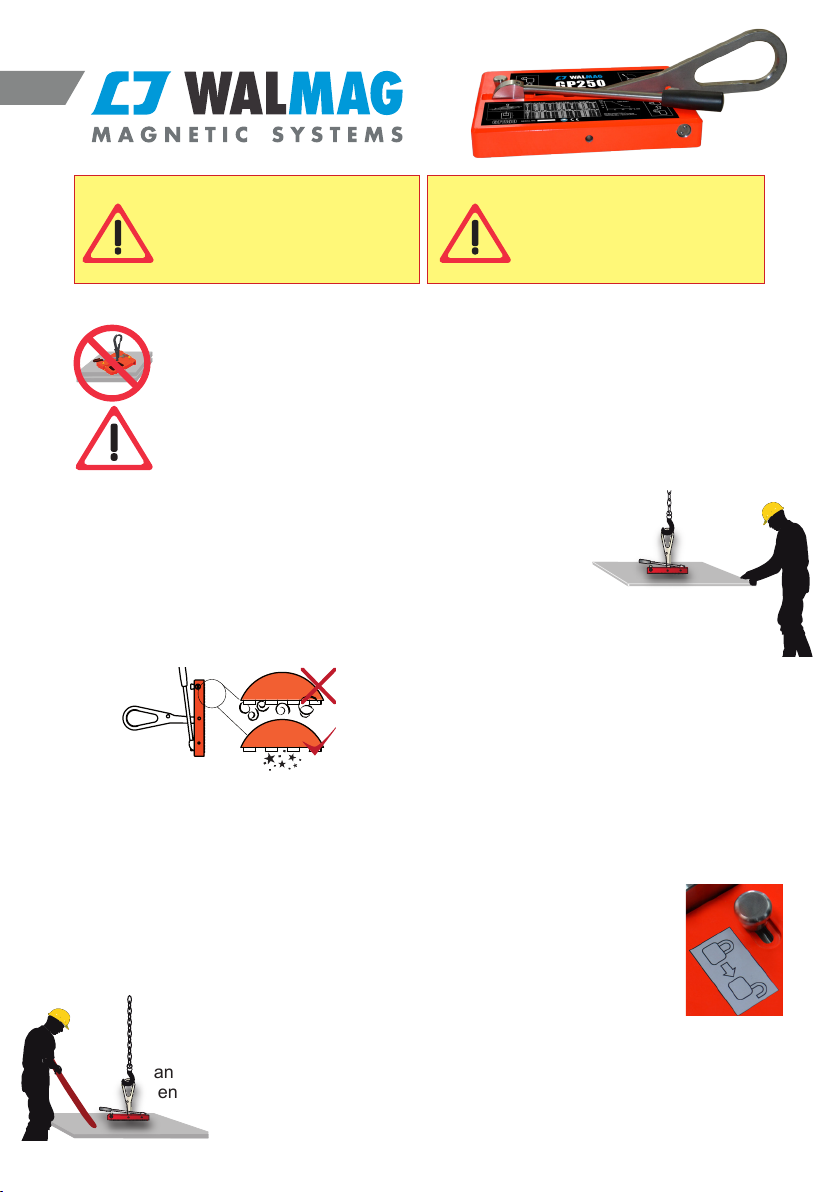
The workload limit of type GP250
Horizontal = 250 kg
Vertical = 80 kg
The workload limit may become less as a
result of:
01. Air gaps between the load and the
magnet, caused by paper, dirt, paint, burrs,
damage, surface roughness etc. either on
the load or the magnet.
02. Thin loads. The thinner the load, the
lower the lifting capacity.
03. Length and width of the load. Long, wide
parts that hang outside the magnet, resulting
in an air gap. This is called the peeling effect.
04. The load material type. In general it
applies that: high alloy percentage = low
lifting capacity.
05. Some alloys are even totally non-
magnetic (e.g. stainless steel 304). The
values in the table on page 4 apply to St.
37 (S 235 JR). For other materials the lifting
capacity will be reduced to the percentages
below:
EN
Workload limit for various materials
H V
Material % kg kg
St 37 [S 235 JR] 100 250 80
E 295 [St 52] 96 240 77
Cast steel 90 225 72
Stainless steel 430 F 50 125 40
Cast iron 45 112 36
Nickel 10 25 8
For other materials consult your supplier.
06. Maximum work load limit is obtained
while magnet is in fully horizontal position
during the transport.
2
UNSAFE APPLICATIONS
NEVER LIFT MORE THAN ONE WORK PIECE AT A TIME (THIN
PLATES)
NEVER LIFT A LOAD WITH A CONTACT SURFACE SMALLER
THAN THE FOOTPRINT OF THE MAGNET.
OPERATION
Read the safety instructions rst before
operating the magnet.
Check the condition of the magnet each
time before use. Wipe the pole shoes on
the magnet and the contact surface of the
workpiece clean. If necessary pile off any
burrs or irregularities.
HORIZONTAL LIFTING:
1. Be sure the lifting eye is unlocked!
Determine the center of gravity of the
work piece as accurate as possible. Lower
the magnet carefully on the designated
position.
Never put your hands between the
magnet and the workpiece !
2. Make sure that release handle is
in the locked position.
3. Lift the load several centimeters
and give the load a rm push to
ensure that it is well gripped.
Never stand under the
load!
4. Guide the load by
holding the corners.
Avoid collisions,
swinging and
shocks. Never
stand under the
load and keep the load
horizontal!
5. Lower the load and stabilize it before
removing/breaking off the magnet. Unlock
the release handle and pull the same to
break off the magnet. Now lift the magnet
away from the workpiece.
WARNING Light workpieces may still
stick to the magnet
VERTICAL LIFTING:
1. Lock the lifting eye in the
vertical position. Unlock the
release handle. Determine
the center line near the top
edge of the work piece.
2. Approach the work piece slowly with the
magnet and position the magnet by means
of the release handle and the hoist.
EN
Never exceed the maximum
weight and/or dimensions
for the material thickness
stated in the table on page 5.
Never place the magnet
over a large hole or bore
3
WARNING Never put your hand between
the magnet and the workpiece!
3. Put the release handle in the locked
position and jerk it rmly to make
sure the magnet is clamped properly.
Now lift the workpiece carefully away from
its support.
WARNING The workpiece will swing away
from the support. Always keep a safe
distance while beginning to lift.
4. Lower the load and stabilize it before
removing/breaking off the magnet.
Unlock the release handle and pull the same
to break off the magnet. Now lift the magnet
away from the workpiece.
TURNING WORKPIECES THROUGH
90 DEGREES
By locking the lifting eye, the magnet can be
used to turn workpieces from horizontal to
vertical and vice versa.
WARNING For this type of manipulation,
the workpiece weight may not
exceed the vertical lift capacity.
From horizontal to vertical
1.Place the magnet on the center line
near the future top
edge of the workpiece.
2. Put the release handle
in the locked position. Jerk
it rmly to make sure the
magnet is clamped properly.
3. Start to lift slowly and
follow the turning of the
workpiece by the hoist.
WARNING The workpiece
will swing as soon as
it is no longer supported. Keep a safe
distance!
4. Lower the load and stabilize it before
removing/breaking off the magnet
5. Unlock the release handle and pull the
same to break off the magnet. Now lift the
magnet away from the workpiece.
From vertical to horizontal
1. Guide the magnet by the
unlocked release handle
and the hoist and place it
on the center line near the
top edge of the workpiece.
2. Put the release handle
in the locked position.
Jerk it rmly to make sure
the magnet is clamped
properly.
3. Start to lift slowly.
WARNING The workpiece may swing
away from the support. Always keep a
safe distance while beginning to lift.
4. Lower the workpiece slowly on the
horizontal support and follow the turning of
the workpiece by the hoist.
Make sure the workpiece is stabilized.
5. Unlock the release handle and pull the
same to break off the magnet. Now lift the
magnet away from the workpiece.
WARNING Light workpieces may still
stick to the magnet.
INSPECTION AND MAINTENANCE OF
THE LIFTING MAGNET
Before every use:
Check the entire magnet visually. Brush the
pole shoes of the magnet and the contact
surface of the workpiece clean. If necessary
le off any burrs or irregularities. Do not
use the magnet if you have discovered any
defects. Check the function of the release
handle and locking pins.
EN
4
L= Length (mm), W = Width (mm)
WORKLOAD LIMIT FOR PLATES (FOR S 235 JR [ST 37])
© Copyright 2014: WALMAG MAGNETICS
All rights reserved. No part of this publication
may be duplicated and/or made public by means
of printing, photocopying, microlm or in any
other manner whatsoever without prior written
permission from WALMAG MAGNETICS. This
also applies to all accompanying drawings and
illustrations.
Do not lift plates thinner than
indicated in the chart!
Horizontal ∆ = ˂ 0,1 mm ∆ = 0,1 - 0,3 mm ∆ = 0,5 mm
s (mm) Lmax x Wmax
(mm) Mmax
(kg) Lmax x Wmax
(mm) Mmax
(kg) Lmax x Wmax
(mm) Mmax
(kg)
˃ 20 1600 x 1000 250 1000 x 700 115 500 x 500 45
12 2000 x 1000 195 1500 x 800 110 1000 x 500 45
10 1700 x 1000 140 1200 x 800 75 1200 x 500 45
8 1100 x 1000 95 1200 x 800 60 1200 x 500 38
5 1500 x 1000 60 1000 x 800 33 1200 x 500 23
3 1700 x 1000 40 1300 x 800 25 1500 x 500 19
Vertical ∆ = ˂ 0,1 mm ∆ = 0,1 - 0,3 mm ∆ = 0,5 mm
s (mm) Lmax x Wmax
(mm) Mmax
(kg) Lmax x Wmax
(mm) Mmax
(kg) Lmax x Wmax
(mm) Mmax
(kg)
˃ 20 1000 x 500 80 500 x 400 30 400 x 300 12
12 1200 x 500 60 600 x 500 28 400 x 300 11
10 1200 x 500 46 500 x 500 20 400 x 300 10
8 1000 x 500 30 500 x 500 15 400 x 300 8
5 1000 x 500 18 500 x 400 8 500 x 300 6
3 1000 x 500 13 500 x 500 6 500 x 400 5
Weekly:
Check the entire magnet, including the lifting
eye and release handle, for deformations,
cracks or other defects. If the lifting eye is
deformed or worn off for more than 10%,
it should be replaced. Check the presence
and legibility of the type plate and instruction
plate. Check the pole shoes. If they are
damaged more than 10% (pits, burrs etc.) the
magnet should be returned to your supplier
or an authorised agent for regrinding. Lifting
capacity is checked following this operation.
Annually:
Have the lifting capacity of your magnet
checked by your supplier or an authorised
agent at least once a year in accordance
with the European standard EN 13155.
NEVER EXCEED EITHER LENGTH, WIDTH OR WEIGHT!
EN
5
Hulínská 1799/1; 767 01 Kroměříž; Czech Republic
Fax: +420 573 351 035; Tel.: +420 573 341 641
www.walmag.cz; [email protected]

Other manuals for GP250

1

Other Walmag Lifting System manuals

Walmag NEO 150 User manual

Walmag

Walmag NEO 150 User manual

Walmag NEO Series User manual

Walmag

Walmag NEO Series User manual

Walmag GP250 Manual

Walmag

Walmag GP250 Manual

Popular Lifting System manuals by other brands

Hatchlift RV Bedlift Kit instructions

Hatchlift

Hatchlift RV Bedlift Kit instructions

APlusLift HW-10KBP Installation manual & operation instructions

APlusLift

APlusLift HW-10KBP Installation manual & operation instructions

Artweger ARTLIFT operation & maintenance

Artweger

Artweger ARTLIFT operation & maintenance

Forankra PLM 100 TRANSLATION OF ORIGINAL INSTRUCTIONS

Forankra

Forankra PLM 100 TRANSLATION OF ORIGINAL INSTRUCTIONS

VMB TL-063B Operating instructions & user manual

VMB

VMB TL-063B Operating instructions & user manual

Hofmann EELR739A Installation, operation & maintenance manual

Hofmann

Hofmann EELR739A Installation, operation & maintenance manual

Vestil HBD Series instruction manual

Vestil

Vestil HBD Series instruction manual

JMP Lux 700 EH operating instructions

JMP

JMP Lux 700 EH operating instructions

Vestil MH-V10 Operating manual & parts list

Vestil

Vestil MH-V10 Operating manual & parts list

KSF GL-500DC Instruction book

KSF

KSF GL-500DC Instruction book

Vestil CART-200-ALUM instruction manual

Vestil

Vestil CART-200-ALUM instruction manual

MoJack EZ Instructions for assembly and operation

MoJack

MoJack EZ Instructions for assembly and operation

rav KPS305C2 manual

rav

rav KPS305C2 manual

SIP 03688 manual

SIP

SIP 03688 manual

SICE SR 80 instruction manual

SICE

SICE SR 80 instruction manual

rav KPS305C2-C3 Original instructions

rav

rav KPS305C2-C3 Original instructions

Genie Z-45 Service and repair manual

Genie

Genie Z-45 Service and repair manual

Global Lift S-350 owner's manual

Global Lift

Global Lift S-350 owner's manual

manuals.online logo
manuals.online logoBrands
  • About & Mission
  • Contact us
  • Privacy Policy
  • Terms and Conditions

Copyright 2025 Manuals.Online. All Rights Reserved.