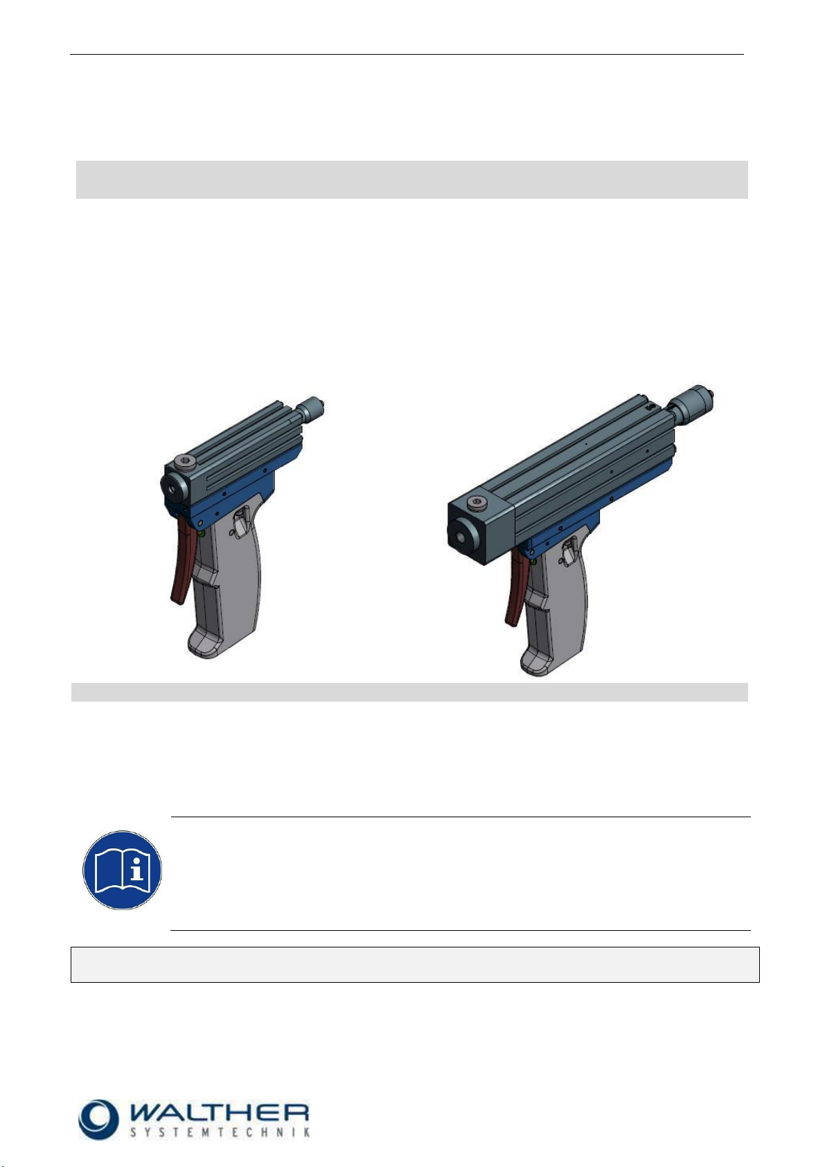
Assembly Instructions –Hand Dosing Device WDVHP-0x-HG
Walther Systemtechnik GmbH –D 76726 Germersheim
Telefon: +49 (0)7274-7022-0 Telefax: +49 (0)7274-7022-91
http://www.walther-2000.de –info@walther-2000.de
EC DECLARATION OF INCORPORATION ....................................................................................................................... 4
1INTRODUCTION ................................................................................................................................................. 5
1.1 TARGET GROUP OF THE ASSEMBLY INSTRUCTIONS ............................................................................................................ 5
1.2 LIST OF SIGNS AND SYMBOLS ....................................................................................................................................... 5
2SAFETY............................................................................................................................................................... 5
2.1 GENERAL INFORMATION ............................................................................................................................................. 5
2.2 DANGERS FROM RESIDUAL ENERGIES............................................................................................................................. 5
2.3 WARRANTY AND LIABILITY........................................................................................................................................... 5
2.4 CORRECT USE ........................................................................................................................................................... 6
2.5 INCORRECT USE ........................................................................................................................................................ 6
2.6 QUALIFICATION OF PERSONNEL .................................................................................................................................... 6
3TRANSPORT ....................................................................................................................................................... 7
3.1 PACKAGING .............................................................................................................................................................. 7
3.2 TASKS BEFORE TRANSPORT .......................................................................................................................................... 7
4DESCRIPTION OF FUNCTION .............................................................................................................................. 7
4.1 DESIGNATED USE OF INCOMPLETE DEVICE ...................................................................................................................... 7
4.2 TYPE LABEL OF INCOMPLETE DEVICE ............................................................................................................................. 7
4.3 FUNCTION................................................................................................................................................................ 7
4.4 TOTAL VIEW /DESCRIPTION......................................................................................................................................... 8
4.5 CONNECTIONS .......................................................................................................................................................... 8
4.6 TECHNICAL DATA ....................................................................................................................................................... 9
5INITIAL START-UP ............................................................................................................................................. 10
5.1 MOUNTING AND INSTALLATION .................................................................................................................................. 10
5.2 ADJUSTING THE INCOMPLETE DEVICE .......................................................................................................................... 10
6OPERATION ..................................................................................................................................................... 11
6.1 GENERAL INFORMATION ........................................................................................................................................... 11
6.2 OPERATION INSTRUCTIONS /OPERATING CONDITIONS .................................................................................................... 11
6.3 OPERATING ELEMENTS ............................................................................................................................................. 11
7TAKING OUT OF SERVICE ................................................................................................................................. 12
7.1 SHORT INTERRUPTION .............................................................................................................................................. 12
7.2 LONG-TERM INTERRUPTION....................................................................................................................................... 12
7.3 SHUTDOWN OF DEVICE............................................................................................................................................. 12
8MAINTENANCE AND REPAIR ............................................................................................................................ 13
8.1 GENERAL INFORMATION ........................................................................................................................................... 13
8.2 ROUTINE TASKS....................................................................................................................................................... 13
8.3 SPARE PARTS .......................................................................................................................................................... 13
8.4 CUSTOMER SERVICE /SUPPORT.................................................................................................................................. 13
9TROUBLESHOOTING ........................................................................................................................................ 14
9.1 GENERAL INFORMATION ........................................................................................................................................... 14
9.2 MALFUNCTIONS ...................................................................................................................................................... 14
10 APPENDIX ........................................................................................................................................................ 15
10.1 DIMENSIONED AND SPARE PART DRAWING –DOSING VALVE WDVHP-02-HG .............................................................. 15
10.1.1 Spare Part List –Dosing Valve WDVHP-02-HG ..................................................................................... 16
10.2 DIMENSIONED AND SPARE PART DRAWING –DOSING VALVE WDVHP-03/04-HG.......................................................... 17
10.2.1 Spare Part List –Dosing Valve WDVHP-03-HG ..................................................................................... 18
10.2.2 Spare Part List –Dosing Valve WDVHP-04-HG ..................................................................................... 18
10.3 ACCESSORIES ..................................................................................................................................................... 19