Walther E-Boxx EV Simulator Parts list manual

Operating instruction and
technical description
EV Simulator for charging devices with
charging plug/charging coupler/charging cable
type 1 and type 2 as service case
Photo: EV simulator/tester with enclosed measuring line.
by

Operating instruction and technical description EV tester type 1 and type 2 - 2.0
©Walther-Werke Ferdinand Walther GmbH Seite 2 von 12
Contents
1Operating instructions EV simulator/tester
2Safety notes
3Operating instructions
3.1 General description
3.2 Hardware
3.2.1
C
omponents
3.2.2
Hardware configuration
4Operation
4.1 Handling
4.2 Features of the EV simulators
4.3 Measuring of built-in resistances inside plug type 2
4.4 Ampacity simulation of resistances inside plug type 2
4.5 Measuring of built-in resistances inside plug type 1
4.6 Checking the PE connection between PWM and vehicle
4.7 Simulation of a fault by means of a switchable fault current
4.8 Simulation of vehicle status B, C, D and display of charging voltage
4.9 Measuring of PWM signal (CP test jack)
5Troubleshooting
6Maintenance
6.1 Battery change
7General technical specifications

Operating instruction and technical description EV tester type 1 and type 2 - 2.0
©Walther-Werke Ferdinand Walther GmbH Seite 3 von 12
1 Operating instructions EV simulator/tester
These operating instructions shall be a valuable help for operation and troubleshooting of the EV simulator/
tester.
This version of the document was last updated in May 2013, version 2.0.
The manual is continuously adapted to the technical enhancement of the devices.
We would appreciate your requests and suggestions or ideas for improvement.
Walther-Werke
Ferdinand Walther GmbH
Postfach 1180
D-67298 Eisenberg
Phone: (+) 49 6351 / 475-0
Fax: (+) 49 6351 / 475-227
E-mail: mail@walther-werke.de
Internet: www.walther-werke.de
2 Safety notes
Besides the technical protective measures, the following precautionary measures also help minimizing the
risk of accidents. Compliance with these recommendations helps minimizing the risk of health damages,
injuries, property damages and production downtimes.
Please see that these precautionary measures will be observed - it's in your own interest.
Train and instruct the operating personnel thoroughly!
The system must only be operated and opened by trained technical staff.
Store these instructions in a way that they are clearly visible and within reach
of the operating personnel.
Acquaint all operators with the safety precautions.
Ensure regular and professional care and maintenance of the system.
Orderly workplace = safety.
Do not remove or deactivate any safeguards. Damaged safeguards either have to be
repaired professionally or have to be replaced.
Protection against electric shock!
Prior to any installation on or near electrical parts always switch off the supply or the
main switch and withdraw the mains plug.
Do not touch live parts.
Use insulated tools.
Never touch electric cables with wet hands
The system (mobile version) must not be permanently exposed to rain or humidity.

Operating instruction and technical description EV tester type 1 and type 2 - 2.0
©Walther-Werke Ferdinand Walther GmbH Seite 4 von 12
3 Operating instructions
3.1 General description
By means of the EV simulator, the functions of charging devices for electric vehicles (charging stations, wall
boxes etc.) and pluggable charging cables (mode 3) can be tested by simulating the electric vehicle. After
installation or for service purposes, this is directly possible at the charging infrastructure.
The present version can be used for type 1 and type 2 charging devices, both with firmly connected charging
cable and with charging sockets and separate charging cable. By means of the provided measuring line, 4
different cable cross sections can be simulated.
The EV simulator comprises the following functions:
•Measuring the built-in resistance inside the type 2 plug (between PP and PE)
•Measuring the built-in resistances inside plug type 1 (between CS and PE) and
checking the interlock's switching function
•Ampacity simulation of a charging cable
•Checking the PE connection between PWM and vehicle
•Simulation of a leakage current > 30 mA from L1 to PE
•Simulation of vehicle status B, C, D and indication of charging voltage via LEDs
•CP test jack for PWM signal
The device simulates both faults which can occur during normal use, and different operating conditions of an
electric vehicle. It only comes to a small power drain of approx. 3 mA from the connected charging device.
Additionally, a load current of max. 6 A can be drawn from the built-in Schuko socket via L1 or a test device
for RCD control can be connected.
Attention:
The Schuko socket shall only be used shortly for measuring purposes. Permanent usage is not allowed.
Furthermore, Walther offers EV simulators both as service-case version for type 1 or type 2 charging devices
with integrated charging jack (acc. to SAE J1772 or IEC 62196, USA, Japan) and with firmly connected
charging cable and charging plug type 2 (acc. to IEC 62196).
Photos: EV tester/simulator for type 2, EV tester/simulator for type 1 and type 2 with firmly connected cable (from left to right)

Operating instruction and technical description EV tester type 1 and type 2 - 2.0
©Walther-Werke Ferdinand Walther GmbH Seite 5 von 12
3.2 Hardware
3.2.1 Components
The EV simulator is built up as stable transport case and is provided with an integrated charging appliance
inlet type 1 and with an integrated charging appliance inlet type 2 for electrical connection. By means of the
special measuring line, the cable cross sections can be simulated. For mobile use there is a carrying strap
available.
Furthermore the connections L1, N and PE are accessible from outside via integrated Schuko socket. The
Schuko socket is placed on the right side of the EV tester. With this, an electric load of up to 6 A can be
connected.
3.2.2 Hardware configuration
Perform the following steps consecutively:
•Remove all parts of the packaging carefully. Avoid damaging.
•Check the device thoroughly regarding transport damages and other damages.
•Supplier and forwarder have to be informed immediately about each damage.
•Check whether all parts have been delivered completely. If applicable, do also consider spare
parts you may have ordered. If parts are missing, inform the supplier immediately.
•Establish the electrical connection of the EV simulator. Check whether L and N are connected
correctly. Check the protective conductor before operating the unit.
•To operate the system, no separate power supply is required. The device is powered by the
connection to the charging device.
If anything is unclear, please contact the supplier.
Photo: EV tester/simulator with operating elements and measuring instrument

Operating instruction and technical description EV tester type 1 and type 2 - 2.0
©Walther-Werke Ferdinand Walther GmbH Seite 6 von 12
4 Operation
4.1 Handling
For simulation purposes, a connection between one of the two charging sockets of the EV simulator (type 1
or type 2) and the charging infrastructure has to be established - either by inserting the firmly connected
charging cable or by using a separate mode 3 charging cable (without simulation of cable cross section or by
means of the provided measuring line for cable cross section simulation).
Photos: Connection possibilities EV tester/simulator type 1, type 2, Schuko socket for load connection and measuring line.
Attention:
Only one of the two charging sockets may be used shortly for measure purposes without permanent load at a
time. A simultaneous insertion of two cables is not permissible and may result in malfunctions and even
cause a short-circuit. Toggling between the two charging sockets is made by the changeover switch in the
middle of the operator panel.
The plug should only be withdrawn when the electric vehicle is switched off (EV status: B, C and D Aus/OFF).
The tester has no integrated interlock.
4.2 Switching on the EV simulator
The EV simulator is switched on by inserting the charging plug into the charging socket respectively by
applying the supply voltage of the charging device. There is no separate switch available. For safety reasons,
the plug has to be withdrawn after termination of the test procedure.
4.3 Measuring of built-in resistances inside type 2 plug
Acc. to IEC 61851-1, there is a resistor available inside the type 2 plug which shows the ampacity of the
charging cable. This resistor can be checked by means of the built-in measuring device.
Coding resistance inside charging plug and charging coupler (type 2)
Power [A] Resistance [Ohm] (rated value)
Cross section [mm²]
13 1500 1,5
20 680 2,5
32 220 6
63 100 16
Table : Ampacity with corresponding coding resistance and cable cross section

Operating instruction and technical description EV tester type 1 and type 2 - 2.0
©Walther-Werke Ferdinand Walther GmbH Seite 7 von 12
Attention:
When measuring the built-in resistors, the switch "simulation power values" (top right) must not be switched
on. Otherwise this may lead to incorrect measurements, since several resistors are simultaneously operative.
Photo: Resistance measurement with charging cable 20 A
With inserted plug, the nominal value, depending on the allowed cross section of the charging cable
should be indicated (see table).
Switch off the measuring device after successful measurement (turn rotary switch to "OFF").
If other or no measured values are indicated, the plug has to be checked.
Attention:
The integrated measuring device is for resistance measuring only and should therefore only be switched on
shortly for measuring the resistances (will result in a longer battery durability). Under no circumstances leave
it switched on during other test procedures with applied voltage.
4.4 Simulation of resistors' ampacity inside plug type 2
Acc. to IEC 61851-1, there is a resistor available inside the type 2 plug which shows the ampacity.
This resistor can be simulated by means of the measuring line provided with the charging device.
Coding resistance inside charging plug and charging coupler (type 2)
Power [A] Resistance [Ohm] (rated value)
Cross section [mm²]
13 1500 1,5
20 680 2,5
32 220 6
63 100 16
Table : Ampacity with corresponding coding resistance and cable cross section

Operating instruction and technical description EV tester type 1 and type 2 - 2.0
©Walther-Werke Ferdinand Walther GmbH Seite 8 von 12
Attention:
For simulation only the provided measuring line may be used. For simulation, the switch "Simulation Power
Values" has to be switched on. Afterwards, the resistance value has to be preset by operating the
corresponding switch. Always only one switch at a time may be switched on. This simulation is only possible
and permissible with type 2.
The measuring line may only be used for this purpose. Charging an electric vehicle with this measuring line is
not permissible / not possible.
Photo: Switch for simulating the ampacity of the charging cable
4.5 Measuring of built-in resistors inside type 1 plug
Acc. to SAE J1772, the type 1 plug contains two resistors (R 6 = 150 Ohm, R 7 = 330 Ohm) and a push
button (S 3). These can be checked by means of the built-in metering device.
Photos: Diagram for type 1 from SAE J1772.

Operating instruction and technical description EV tester type 1 and type 2 - 2.0
©Walther-Werke Ferdinand Walther GmbH Seite 9 von 12
Setting the rotary switch of the measuring device to the measuring range Ω(Ohm) activates the measuring
process. If there is no indication please check or replace the batteries of the measuring device.
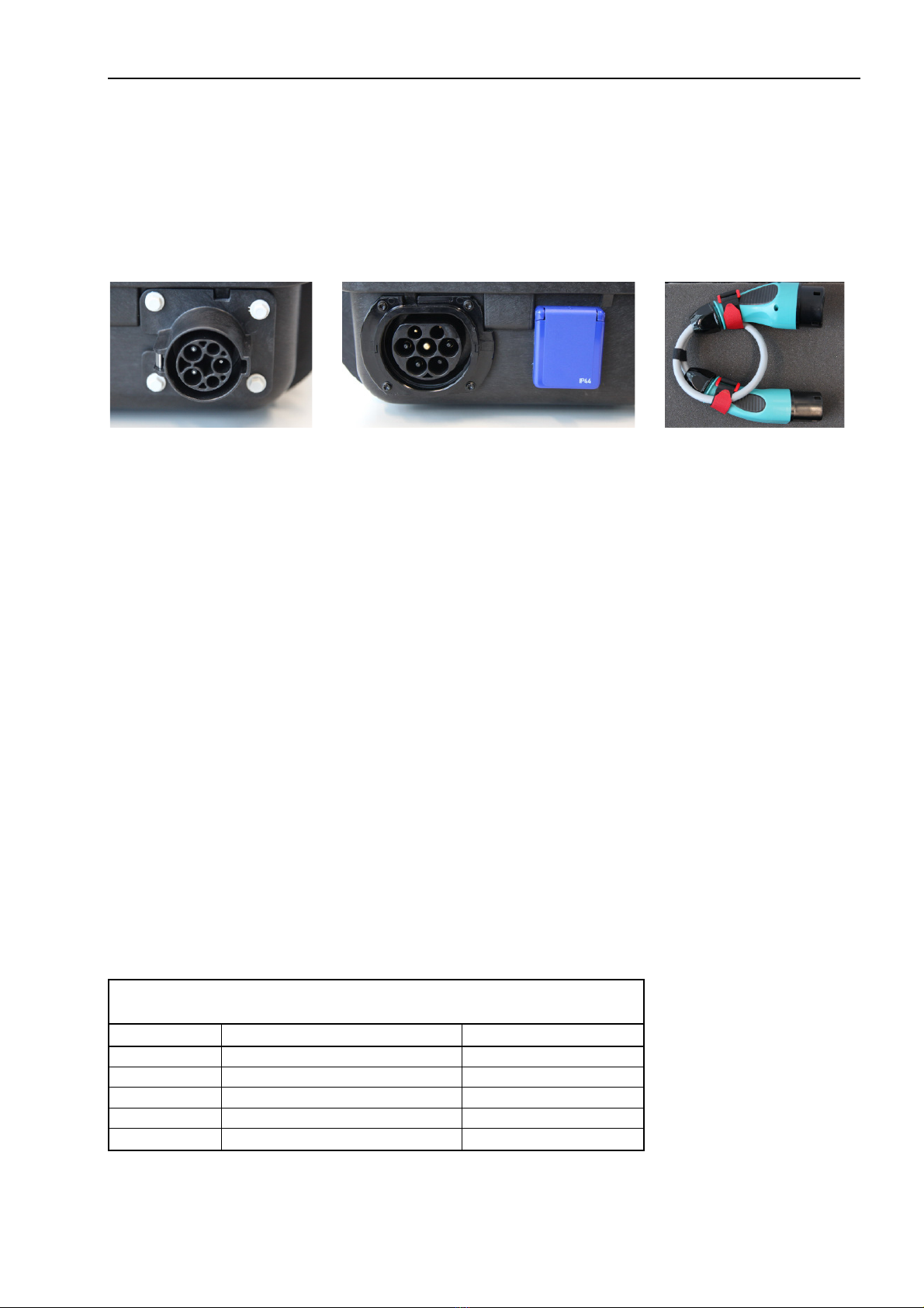
Photos: Resistance measurement with connected cable and actuated pushbutton
With inserted plug, the nominal value 150 Ωshould be indicated. In this case, the pushbutton on the plug is
not pressed. By pressing the pushbutton on the plug, the nominal value 480 Ωshould be indicated. After
successful measurement, switch off the measuring device (turn rotary switch to OFF).
If other or no measured values are indicated, the plug and the relevant switch positions have to be checked.
Attention:
The integrated measuring device is for resistance measuring only and should therefore only be switched on
shortly for measuring the resistances (will result in a longer battery durability). Under no circumstances leave
it switched on during other test procedures with applied voltage.
4.6 Checking the PE connection between PWM and vehicle
The PE EV switch is used to check the PE connection. In switch position Ein/ON the PE is connected, in
switch position Aus/OFF it is interrupted. Thus the connection between PE and CP on the vehicle side is
interrupted and the charging process should be switched off by the charging device. Now the charging device
should no longer react to operating the switches Status EV (signal CP) B, C or D.
4.7 Simulation of a fault by means of switchable fault current
To test the triggering of the RCD in case of error, a switchable leakage current (> 30 mA) is created. This
leakage current is conducted from L1 to PE via an integrated resistance (3,3 kΩ). The leakage current is
created by pressing the FI/RCD pushbutton shortly (switch position Ein/ON). The protective device inside the
charging infrastructure has to trigger immediately. In case of correct switching off the red LED flashes shortly
and the RCD triggers. The charging process should be interrupted directly.
Attention:
If the LED FI/RCD shines permanently while the pushbutton is pressed, release the pushbutton immediately.
Then the protective device FI/RCD respectively the wiring of the installation has to be checked.
In case of single-phase use of the charging infrastructure, care must be taken to ensure that L1 and N have
not been interchanged on the charging device, i.e. it must be possible that a leakage current can flow to PE.
(L1 = L and N = N). Only under these circumstances can the test be carried out correctly.

Operating instruction and technical description EV tester type 1 and type 2 - 2.0
©Walther-Werke Ferdinand Walther GmbH Seite 10 von 12
4.8 Simulation of vehicle status B, C, D and display of charging voltage
The vehicle status can be simulated by means of different switch positions of the switches B, C and D.
Status B Switch B Ein/ON
Status C Switch B and C Ein/ON
Status D Switch B and D Ein/ON
Table : EV status and switch position
On single-phase charging devices, the switched-on charging voltage is only indicated at LED L1.
On three-phase charging devices, the switched-on charging voltage is indicated at LEDs L1, L2 and L3.
Photo: Switch for EV status simulation
By operating switch B, vehicle status B is simulated. In this status, the electric vehicle is connected to the
charging device and is ready to be charged (PWM signal: 9 V).
By additionally operating switch C (i.e. B and C), the electric vehicle requests charging current and it is
switched on by the charging device. Please note that no thereby no charging power is withdrawn. The electric
vehicle which is simulated by the EV tester would be charged now (PWM signal: 6 V)
By operating switch D instead of C (i.e. B and D), the electric vehicle requests ventilation during the charging
process (PWM signal: 3 V). The charging device has to react accordingly.
Frequency and pulse width of the PWM signal remain constant during simulation.
4.9 Measuring of PWM signal (CP test jack)
On the BCN female jack, there is the PWM signal available for display and measuring. It can for example be
evaluated with an oscilloscope.
Attention:
This measurement has to be carried out "unearthed, without PE". Otherwise checking the PE connection
(chapter 4.6) is not possible.

Operating instruction and technical description EV tester type 1 and type 2 - 2.0
©Walther-Werke Ferdinand Walther GmbH Seite 11 von 12
5 Troubleshooting
Error, fault Cause Remedy
Measuring device
of EV simulator
does not react
Batteries are empty
Exchange batteries of measuring device (see
maintenance).
Attach the device correctly.
EV simulator
does not react
Voltage supply is missing
Plugs are not inserted correctly
Switch positions are wrong
Check voltage supply of charging infrastructure
Check pre-fuses
Check plug connection
Check switch positions
RCD does not trigger;
LED is shining
permanently while
pushbutton FI/RCD is
pressed
Plugs are not inserted correctly
RCD does not work correctly or
is not available.
Check plug connection
Release pushbutton immediately
Check RCD and switch on again
Check wiring of the installation
The oscilloscope
connected to the BNC
female jack delivers no
signal
BNC plug is not inserted
correctly
Switch positions are wrong
Check switch positions B,C,D
Check position of switch type 1 – type 2
Check BNC plug
Check oscilloscope settings
Charging device does
not react to simulation
Plug is not inserted correctly
Switch type 1 – type 2 in wrong
position
Switch PE is Off
PE is interrupted
Check connection. Only one connection may be
occupied.
Check position of switch type 1 – type 2
Switch on the PE switch
Check PE
No line simulation
possible
Measuring line defective or
not available
Switch positions during
simulation of power values are
wrong
Use measuring line
Switch on the "simulation power values" switch
More than one switch (13, 20, 32 63 A) is switched
on
Wrong measuring
values with the coding
resistor
Measuring line inserted
Switch "Simulation power
values" wrong
Remove measuring line
Switch off the "simulation power values" switch
Faulty resistor inside the cable

Operating instruction and technical description EV tester type 1 and type 2 - 2.0
©Walther-Werke Ferdinand Walther GmbH Seite 12 von 12
6 Maintenance
The EV simulator does not require any considerable maintenance. If necessary the battery of the built-in
measuring device has to be exchanged.
6.1 Battery change
Loosen the two PVC screws and carefully open the measuring device by loosening the screws on the
backside. Exchange the used batteries (LR 44 or identical in construction). Close the device and fix it on the
front plate.
Attention:
In any case, the EV tester has to be separated from the charging device prior to any maintenance work!
Maintenance work may only be carried out by trained specialised staff.
To avoid increased contact resistances, the contacts on the charging sockets of the EV tester and on the
plugs of the charging cable and the measuring line have to be checked.
7 General technical specifications
Length
approx. 360 mm
Width
approx. 310 mm
Height approx. 200 mm
Weight approx. 2,7 kg
Voltage supply 230V / 400V
50 Hz
Switchable leakage current (from L 1 to PE) > 30 mA corresponding to
resistance 3,3 kΩ
Charging sockets for connection with infrastructure Type 1 (5-pole)
Type 2 (7-pole)
Measuring line, special version
Plug type 2
Coupler type 2
7-pole wired through
Schuko socket for load connection on L 1. 230 VAC, max. 6 A
Table of contents
Other Walther Test Equipment manuals