WARDRAY PREMISE MR5505 User manual

JANAURY 2020 GEN.S.20/301
MR5505
MR Conditional Adjustable Height
Cube Trolley and Fixed Top Trolley
OPERATORS MANUAL

2
Introduction
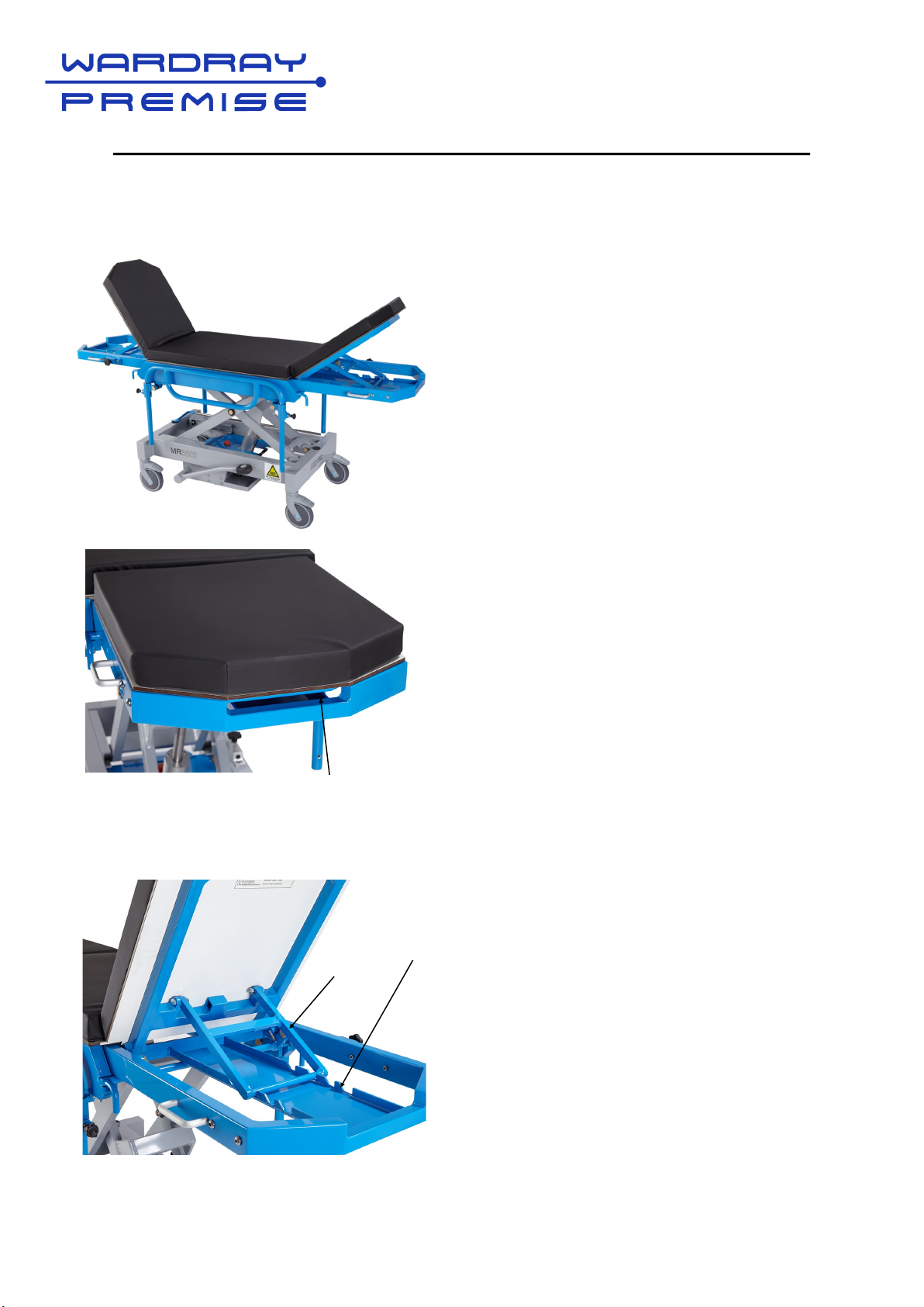
Thank you for purchasing this MR Conditional product. Manufactured and tested to the highest
standards it is guaranteed MR Conditional to 7.0T.
Our products are manufactured by Wardray Premise Ltd to BS EN ISO 13485:2016 and are CE
marked.
Manufacturing address:
Wardray Premise Limited, Northern Regional Office, Unit 2,
Springvale Works, Elland Road,
Brighouse, West Yorkshire, HD6 2RN, UK
To ensure that you obtain maximum benefit from your product, please take a few minutes to read
the enclosed information regarding operation, service and maintenance.
If you have any problems in the meantime or would like any advice about this or any other MR
products from the Wardray Premise range, please contact us at our Head Office:
Wardray Premise Limited, Hampton Court Estate, Summer Road
Thames Ditton, Surrey, KT7 0SP, UK
Tel: +44 (0) 20 8398 9911
Fax: +44 (0) 20 8398 8032
E-mail: sales@wardray-premise.com
Kindly note:
If you modify a Wardray Premise product you will invalidate your warranty.
Unless you have our express written permission to modify a product, we transfer all liabilities for
modified products to you.
EU Authorised Representative:
Advena Ltd
Tower Business Centre
2nd Floor, Tower Street
Swatar
BKR 4013
Malta

3
Safety Definitions for MRI as Defined by International Standard
F2503-20
MR SAFE:
An item that poses no known hazards resulting from exposure to any MR
environment. MR SAFE items are composed of materials that are electrically
non-conductive, non-metallic, and non-magnetic.
MR CONDITIONAL:
An item with demonstrated safety in the MR environment within defined
conditions including conditions for the static magnetic field, the time-varying
gradient magnetic fields and the radiofrequency fields.
Supplementary marking – additional information that, in association with
marking as “MR CONDITIONAL,” states via additional language the conditions
in which an item can be used safely within the MR environment.
MR UNSAFE:
An item which poses unacceptable risks to the patient, medical staff or other
persons within the MR environment.

4
Specification
The MR5505 Trolley is designed to be MR Conditional and is manufactured and tested to
the highest standards.
The MR5505 is constructed from 3 main materials, these being aluminium, brass and 316
stainless steel.
The Top Frame, Pivot Sections, X Frames and Base frame are all manufactured from
aluminium, which whilst being MR Compatible is also lightweight, this aids the easy
movement of the trolley.
Brass and stainless steel materials are used in the manufacture of the Pivot Bolts and
parts within the hydraulic pump and cylinder.
It is advisable that the product is inspected and serviced every 12 months by a Wardray
Premise trained engineer.
A service contract package is available, and details are available upon request from our
Service Department on +44 (0) 20 8398 9911.
For international customers please contact your local Wardray Premise representative for
assistance.
Maximum patient weight 34 Stone / 220 Kg
Important Information
This MR Conditional trolley has been designed for adult patients. If you use the trolley to
transport a child extra care should be taken particularly regarding the movement of the
child across the mattress and the potential for their limbs or other body parts to protrude
through the trolley sides, potentially causing injury / harm. Wardray Premise Ltd also offer
a range of paediatric trolleys with cot bumpers for the safe transportation of children.
Table top size
mm
1900 x 500
Max length
mm
1900
Max width
mm
575
Low height
mm
630
Top height
mm
950
Max load
Kg
220
Fixed Top
Trolley
Cube Trolley 1900 x 500 1900/1055
(folded)
575 630 950 220

5
MR5505 Cube Trolley parts reference
Pedal
Plunger
Pivot section
Pull handle
Backrest
View behind backrest
Cot sides
Handle on pivot
section
Castor
Brake Lever
IV Pole stored on left hand
side of trolley
Backrest support
Pivot section
Handle on pivot
section
Lobe knob
for IV pole
Serial Number under backrest
Castor
Brake Lever
Plunger
IV Pole (stored)

6
MR5505 Fixed Top Trolley parts reference
Pedal
Plunger
Backrest
View behind backrest
Cot sides
Brake Lever
IV Pole stored on left hand
side of trolley
Backrest support
Lobe knob
for IV pole
Serial Number under backrest
Castor
IV Pole (stored)
Plunger

7
Operating Instructions
Raising and Lowering Trolley
There is a pedal located each side
of the trolley.
To raise the trolley place your foot
on the black rubber (Fig.1) and push
down until you feel it stop, lift foot
and allow the pedal to raise until it
stops, repeat until desired height is
reached, or top height is achieved.
To lower, place foot on black rubber
and push down until you feel the
stop, then push further and table top
will lower. Remove foot when table
reaches desired height or lowest
position is achieved.
Please note the trolley is fitted with a safety ‘blow-off ‘system, this allows you to pump
up the trolley to the top height without damaging the cylinder or trolley.
Fig 1

8
Operating Instructions - Cube Trolley
Pivot Sections
When the Cube Trolley is not in use it
folds away into a handy size;
1040mm (L) x 575mm (W) x 630mm (H).
This is particularly convenient when
space is at a premium.
The Cube Trolley has two pivot sections
one on each end (Fig 1). The Pivot
sections can be raised from vertical to
horizontal by simply grasping the handles
on either side of the pivot section, and
raising to slightly above horizontal, you
will then hear the lock bar click into place.
Make this adjustment without the
patient on the trolley.
To lower the pivot section, hold the raised
end of the pivot section and raise slightly
above horizontal, place your finger
around the blue pull handle (Fig 2) and
pull backwards, this will disengage the
lock bar. Hold the pull handle until the
lock bar is clear, release the pull handle
and simply lower the pivot section until it
rests on the base.
Make this adjustment without the
patient on the trolley.
Fig1
Fig 2

9
Operating Instructions - Cube Trolley and Fixed Top Trolley
Backrest
Both ends of the trolley have a manual
backrest. (Fig 1)
To raise the backrest place your hand into
the pocket (Fig 2) at the end of the pivot
section and lift, positioning backrest support
into one of the 3 set heights (Fig 3).
To lower the backrest hold the backrest
board from the underside and raise until the
backrest support (Fig 4) can swing freely, pull
the backrest support towards the rear of the
trolley and lower the board.
When moving the backrest into its flat/
horizontal position, ensure nothing can
become trapped between the framework and
the backrest
Please note that when adjusting the
backrest position while a patient is on the
trolley we strongly advise this is done by
two members of staff, one to support the
patient and one to adjust the backrest.
Fig 2
Fig 3
Fig 4
Fig 1

10
Operating Instructions
Cot Sides The trolley is fitted with raise and lower cot
sides (Fig 1) these protect the patient
during transportation to and from the ward.
The cot sides should not be used to
steer/push the trolley.
Fig 1
Depending on the design of the trolley, it will be fitted with one or other of the plungers indicated
below; Standard Plunger (Fig 2) or Flag Plunger (Fig 4)
Standard Plunger
Disengaged Fig 3
To operate the Standard Plunger:
To lower the cot sides, pull the black
plunger to disengage (Fig 3) and lower that
cot side end until it stops*.
To raise the cot sides, hold the top rail in
the centre and lift until the plunger
engages.
To operate Flag Plunger:
To lower the cot sides, disengage the black
’flag’ plunger by pulling and turning
upwards until it snaps into the notch
vertically and pointing upward. (Fig 5)
Lower the cot side until it stops*.
To raise the cot sides, hold the top rail in
the centre and lift upwards. Pull and rotate
the flag plunger until it snaps into the
vertical downward position (Fig 4). Once
partially turned the flag will snap into the
notch at the bottom to be in the engaged
position.
Standard Plunger
Engaged Fig 2
Flag Plunger
Engaged Fig 4
Flag Plunger
Disengaged Fig 5
Standard Plunger
Flag Plunger
IMPORTANT NOTE: Do not attempt to push
the cot sides down while the plunger is still
engaged.

11
Operating Instructions
Raising and Lowering Trolley
Please note the trolley is fitted with a safety blow off system, this allows you to pump up
the trolley to the top height without damaging the cylinder or trolley
Fig 4Fig 3Fig 2
Fig 1
There is a pedal located each side of the trolley (Fig.1).
To raise the trolley place your foot on the black rubber
(Fig.2) and push down until you feel it stop, lift foot and
allow the pedal to raise until it stops, repeat until desired
height is reached, or top height is achieved (Fig 3).
To lower, place foot on black rubber and push down until
you feel the stop, then push further and table top will lower
(Fig 4).
Remove foot when table reaches desired height or lowest
position is achieved.

12
Operating Instructions
Castors
The trolley is fitted with four 150mm diameter, individually braked castors.
To engage the brakes, place your foot on the front part of the brake lever (Fig 1) and push down
firmly, the brake will lock in place and stop the castor from moving.
To release the brake place your foot on the rear part of the brake lever (Fig 2) and press down
firmly, this will release the brake.
If your trolley is fitted with a Directional Locking Castor, this is denoted by the green locking
lever. To engage a directional locking castor:
1Stand at the head end of the trolley, push the trolley forward by approximately 1 metre.
This will ensure that the directional locking castor is the ‘trailing’ position under the trolley
(Fig 3).
2Engage the directional lock by pushing down firmly on the green lever (Fig 4).
3To release the directional lock place your foot on the green lever, on the rear/raised part,
and press firmly to release (Fig 5).
Fig 1 Fig 2
Press down
firmly to release
Press down
firmly to lock
Fig 3
Push forward from
head end
Locked for Directional use
Fig 4 Fig 5
Unlocked
123

13
Operating Instructions
IV Pole
The trolley is fitted with a single hook IV Pole.
(Fig 1)
There are two brackets, one on each pivot
section that the IV Pole can locate into. The
IV Pole can be raised and lowered to any
height and locked into position by means of a
lobe knob. (Fig 2).
When not in use the IV Pole can be stored
safely on the base frame of the trolley (Fig 3).
Fig 1
Fig 2
The IV Pole is manufactured from 316
stainless steel, and is stamped with the serial
No. of the trolley.
As a safety precaution, please check the
serial No. of the IV Pole matches the
trolley’s serial No. before using.
Fig 3

14
Do’s and Dont’s
Do ensure the following are observed:
The trolley should only be used by properly trained staff at all times.
The trolley must be operated by 2 people when transporting a patient.
When a patient is on board, the cot sides must be in an upright locked position before
moving the trolley or adjusting the trolley height.
The trolley must only be used for the purpose for which it was designed.
Don't:
Lift the trolley upwards by the top.
Push the trolley over rough or uneven ground.
Drop heavy or sharp objects onto the solid plastic table top.
Push the trolley by the cot sides, these are for patient safety only.
Place a weight of over the equivalent of 34 Stone (220Kg/485lbs) onto the trolley.
Place a weight of over the equivalent of 7 Stone 12lbs (45Kg/99lbs) on either of the Pivot
Sections.
Spill oil or other liquids/chemicals on the mattress.
Attempt to rectify any faults on the trolley without contacting Wardray Premise Ltd.
Use the trolley without a mattress.
Do not allow staff or patients to fix or store any items on the trolley unless you have verified
the MR safety of the items.
The trolley should be serviced regularly, but only by Wardray Premise trained
engineers, as they will carry the correct spares to guarantee safety and
compatibility of the trolley. Failure to comply with this will invalidate your warranty
and could compromise its MR compatibility and therefore safety.

15
General Maintenance
It is strongly recommended that the following checks are carried out on a weekly basis by
trained personnel, to ensure trouble free operation of the trolley.
Check the solid plastic table top for cracks or other obvious signs of damage or
contamination. Report any damage found.
Check mattress for any sign of damage or contamination. Report damage or clean where
necessary with mild soap and water.
Check castors for free movement and the braking mechanism for functionality, check and
remove any debris that may have been caught between the forks and around the axles,
This is a common occurrence and can lead to a shortened life expectancy of the castor if
left unattended.
Check the pivot sections (Cube Trolley) for ease of movement and the lock bar mechanism
Check the backrest function, including the ability to lock into each of the positions.
Particular attention must be made to the raise and lower function. Raise and lower the
trolley a couple of times before using, check for any leaks, especially if the trolley has not
been used for a long period of time.
Check the cot sides for functionality and damage, especially the cot side brackets and
plungers, as these take the brunt of any impacts from the side. Ensure that the plungers
work freely and locate into the holes.
Ensure that the IV Pole fitted is correct and the serial no. corresponds with the trolley serial
no. located on the inside of the backrest board (see page 5 for location). Make sure there
are no sharp burrs from misuse.
Please register your product with us, via the Warranty Registration Form (see page 17), for ease
of contact in case of urgent upgrades or recalls.
If the unit is damaged please do not attempt to repair as this could invalidate your
warranty and could compromise its MR integrity and therefore safety, please call or
email Wardray Premise Limited:
T: +44 (0) 20 8398 9911
F: +44 (0) 20 8398 8032
E-MAIL: sales@wardray-premise.com
Please include the product code and the product’s serial number when
contacting Wardray Premise.

16
Cleaning
This product should be washed with a disposable cloth wrung out in a solution of warm water and
detergent. The product should be rinsed with warm water and dried thoroughly with paper towels.
If required the product can be washed down with hand hot sodium hypochlorite solution up to 1%
or 10000 parts per million chlorine combined with a detergent. Alternatively, follow your local
guidelines or instructions.
If any of the above give cause for concern, please contact your Wardray Premise service
provider.
EU Declarations of Conformity and Magnetic Testing
Documentation is available upon request.

17
Table of contents
Other WARDRAY PREMISE Medical Equipment manuals