8
Operating Instructions
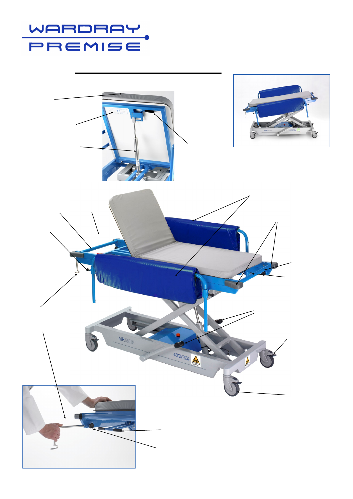
Cot Sides
The trolley is fitted with raise and lower cot
sides (Fig 1) these protect the patient
during transportation to and from the ward.
The cot sides should not be used to
steer/push the trolley.
When lowering cot sides ensure
nothing can become trapped between
the cot sides and or the bed.
Fig 1
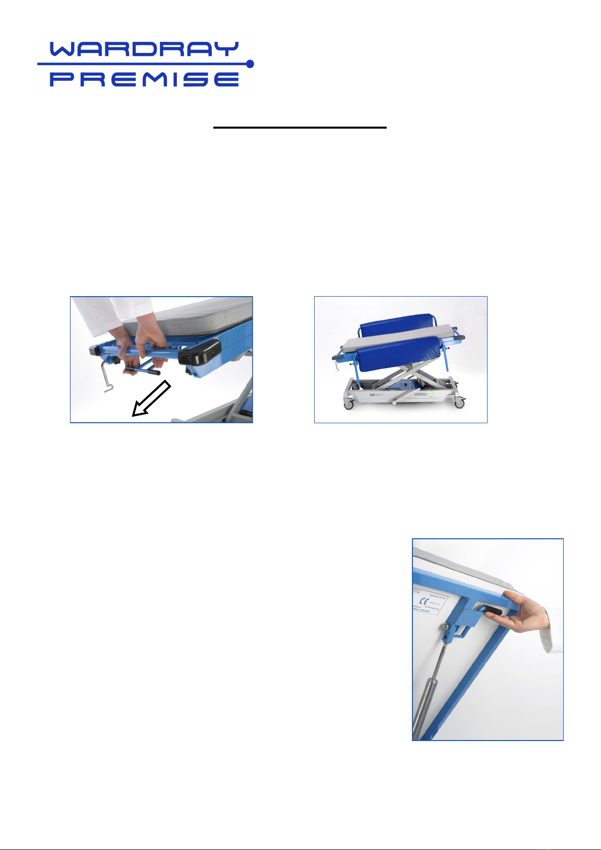
Standard Plunger
disengaged Fig 3
Depending on the design of the trolley, it will be fitted with cot side plungers indicated below;
Standard Plunger (Fig 2) or Flag Plunger (Fig 4). Each cot side has 2 plungers.
To operate the Standard Plunger:
To lower the cot sides, pull the black
plunger to disengage (Fig 3) and lower
that cot side end until it stops*.
To raise the cot sides, hold the top rail in
the centre and lift until the plunger
engages.
To operate Flag Plunger:
To lower the cot sides, disengage the
black ’flag’ plunger by pulling and
turning upwards until it snaps into the
notch vertically and pointing upward.
(Fig 5)
Lower the cot side until it stops*.
*If, after plunger has been released the
cot side is not in its lowest position,
ensuring plunger is disengaged, gently
push down on the centre of the top rail.
To raise the cot sides, hold the top rail in
the centre and lift upwards. Pull and
rotate the flag plunger until it snaps into
the vertical downward position (Fig 4).
Once partially turned the flag will snap
into the notch at the bottom.
IMPORTANT NOTE: Do not attempt to push
the cot sides down while the plunger is still
engaged.
Engaged
Fig 2
Engaged
Fig 4
Flag Plunger
Disengaged Fig 5
Standard Plunger
Flag Plunger