WAREMA D1.P.10 Operation manual

Installation and care
instructions
WAREMA insect screen swinging door
For qualified technicians only
To be handed over to the opera-
tor.
Please keep for future use.
Valid from 4 May 2018
2023248 [Rev. 4 - en]/2018-05-04 Page 1 | 8
Installation and care
instructions
WAREMA insect screen swinging door
For qualified technicians only
To be handed over to the opera-
tor.
Please keep for future use.
Valid from 4 May 2018
2023248 [Rev. 4 - en]/2018-05-04 Page 1 | 8
1 Safety and product information
Warnings are marked in the instructions with this
symbol.
Read through the product instructions before
use.
Observe all safety and setting instructions.
The basic safety instructions
can be viewed under
(www.warema.de/Sicherheitshinweise).
Target group
These instructions are intended for use by persons who
install, operate, care for and/or maintain the product.
Persons installing the product must be familiar with the
following areas: occupational safety, accident prevention
regulations, working with ladders, usage of fixing materials,
and the commissioning and operation of the product.
If the fitter lacks any one of these qualifications, the work
must be carried out by a specialist fitting company.
Permissible activities
Performing tasks on the product that are not described in
these instructions is not permissible. No other alterations
are to be carried out on the product other than as described
in these instructions without the written approval of
WAREMA.
The product is a frame with insect screen gauze that serves
as a door element and is installed outdoors on frequently
used openings (such as balconies or patios).
Model overview
Models Description
D1.P.10 One-wing closed mounting frame
without leg
Used with aluminium and plastic
doors
D1.P.11 One-wing closed mounting frame
without leg
Used with two-wing aluminium and
plastic doors with lock plate
D1.P.20 One-wing closed mounting frame
with surrounding leg
Used with offset doors
D1.P.25 One-wing closed mounting frame
with surrounding leg
Used with aluminium and plastic
doors with heavily rounded or sloped
window frames
D1.P.30 One-wing, closed mounting frame
with 3-sided leg
Used with offset doors
D1.P.35 One-wing, closed mounting frame
with 3-sided leg
Used with aluminium and plastic
doors with heavily rounded or sloped
window frames
D1.P.40 One-wing open mounting frame with
3-sided leg
Used with plastic doors with close-
fitting roller shutter curtain
D1.P.41 One-wing open mounting frame with
3-sided leg
Used with two-wing plastic doors
with lock plate for close-fitting roller
shutter curtain
D1.P.50 One-wing open mounting frame with
3-sided leg + L-guide profile
Used with wooden doors with close-
fitting roller shutter curtain
D1.P.51 One-wing open mounting frame with
3-sided leg + L-guide profile
Used with two-wing wooden doors
with lock plate for close-fitting roller
shutter curtain
Tab. 1: Description of different models

Installation
Page 2 | 8 2023248 [Rev. 4 - en]/2018-05-04
Models Description
D1.P.70 One-wing open mounting frame
without leg
Used with plastic doors with lateral
close-fitting roller shutter guide rail
D1.P.80 One-wing open mounting frame
without leg + L-guide profile
Used with wooden doors with lateral
close-fitting roller shutter guide rail
Tab. 1: Description of different models
1
2
3
4
1Mounting frame 3Middle hinge
2Insect screen
swinging door
4Spring tension system
Fig. 1: Parts overview of insect screen swinging door
2 Installation
NOTICE
Lack in technical qualifications!
Improper installation may damage the product and
adjacent parts.
If technical qualifications for installing the product
are not available, have the product installed by a
qualified specialist.
2.1 Scope of delivery
INFO
Check the scope of delivery against the delivery
note.
Check the parts to make sure they are not
damaged.
Compare the situation on-site with the order
data.
If any items are damaged or not as specified
in the order, stop installation and contact
WAREMA.
Designation Use
Screw anchor SX
6x30
Chipboard screw
4x40 AW20 with pan
head
Fixing material on
masonry
Pan head self-tap-
ping screw DIN7981
3.5x13 AW10
Fixing material on
plastic/aluminium
Chipboard screw
3.5x15 AW20 with
pan head
Fixing material on
wood
Tab. 2: Fixing material for mounting frame
2.2 Installing the mounting frame on the
reveal
Removing the transport lock
Remove the transport
lock (only with open
mounting frame)
Attaching the mounting frame
INFO
When installed on the reveal, the swinging door
remains in the mounting frame (delivery condition)
and does not have to be disassembled.
Note the special feature with frame divider
(Page 4).
A1
D1
D2
A2
Hold the mounting
frame horizontally
against the reveal.
Watch the edge dis-
tances.
Bei Ausführung mit
Rahmentrennung auf
den 90° Winkel achten!
Check diagonals D1
and D2.
Check distances A1 and
A2. Align the mounting
frame if necessary.
1
2
=
=
Check that the dis-
tances of the door to the
mounting frame (mag-
net side) are equal.

Installation
2023248 [Rev. 4 - en]/2018-05-04 Page 3 | 8
1
2
Transfer the drill hole
position.
Drill the fixing holes.
Attach the mounting
frame.
Press the cover caps in-
to place.
2.3 Installing the mounting frame in the reveal
Detaching the swinging door from the mounting frame
INFO
When installing in the reveal, the swinging door must
first be removed from the frame.
1
2
Lightly press the swing-
ing door into place.
Remove the cord from
the deflection roller.
1
2
Loosen the threaded
pins.
Push the bracket away
from the hinge.
Loosen the threaded
pin.
1
2
Push the upper spring-
loaded hinge pin down,
for example with a hex
key.
Swivel the swinging
door out of the seat and
remove from the mount-
ing frame.
Removing the brushes from the mounting frame
INFO
For installation in the reveal, the two lateral (hinge-
side) brushes and the upper brush must be removed
from the mounting frame.
The brushes must not be swapped accidentally
when reinstalling.
Position of the brushes to
be removed.
Fix the middle hinge to
the mounting frame with
adhesive tape.
Pull the brushes out
of the recesses in the
mounting frame.
Removing the transport lock
Remove the transport
lock.

Installation
Page 4 | 8 2023248 [Rev. 4 - en]/2018-05-04
Attaching the mounting frame
INFO
Note the special feature of the frame divider
(Page 4).
D1
D2
A1
A2
Position the mounting
frame in the reveal.
Bei Ausführung mit
Rahmentrennung auf
den 90° Winkel achten!
Check diagonals D1
and D2.
Check distances A1 and
A2. Align the mounting
frame if necessary.
Transfer the drill hole
position.
Drill the fixing holes.
Attach the mounting
frame.
Push the brushes back
into the mounting frame
over the recesses.
Remove the adhesive
tape from the hinge.
Attaching the swinging door to the mounting frame
Insert the swinging door
in the lower hinge.
2
1
Push the upper spring-
loaded hinge pin down-
ward.
Swivel the swinging
door into the mounting
frame.
Slowly release the up-
per hinge pin and let it
engage in the seat.
Tighten the threaded pin
and secure the hinge in
position.
1
2
Slide the bracket into
the middle hinge.
Tighten the threaded
pin.
1
2
Lightly press the swing-
ing door into place.
Place the cord around
the deflection roller.
1
2
=
=
Check that the dis-
tances of the door to the
mounting frame (mag-
net side) are equal.
Readjust the mounting
frame if necessary.
2.4 Installing the frame profile (with frame
divider)
INFO
Only necessary with P.11, P.41 and P.51.
6
Position the frame pro-
file vertically and at an
angle to the mounting
frame.Maintain a dis-
tance of 6mm between
the swinging door and
the frame profile.
1
2
Transfer the drill hole
position.
Drill the fixing holes.
Attach the frame profile.
Press the cover caps in-
to place.

Installation
2023248 [Rev. 4 - en]/2018-05-04 Page 5 | 8
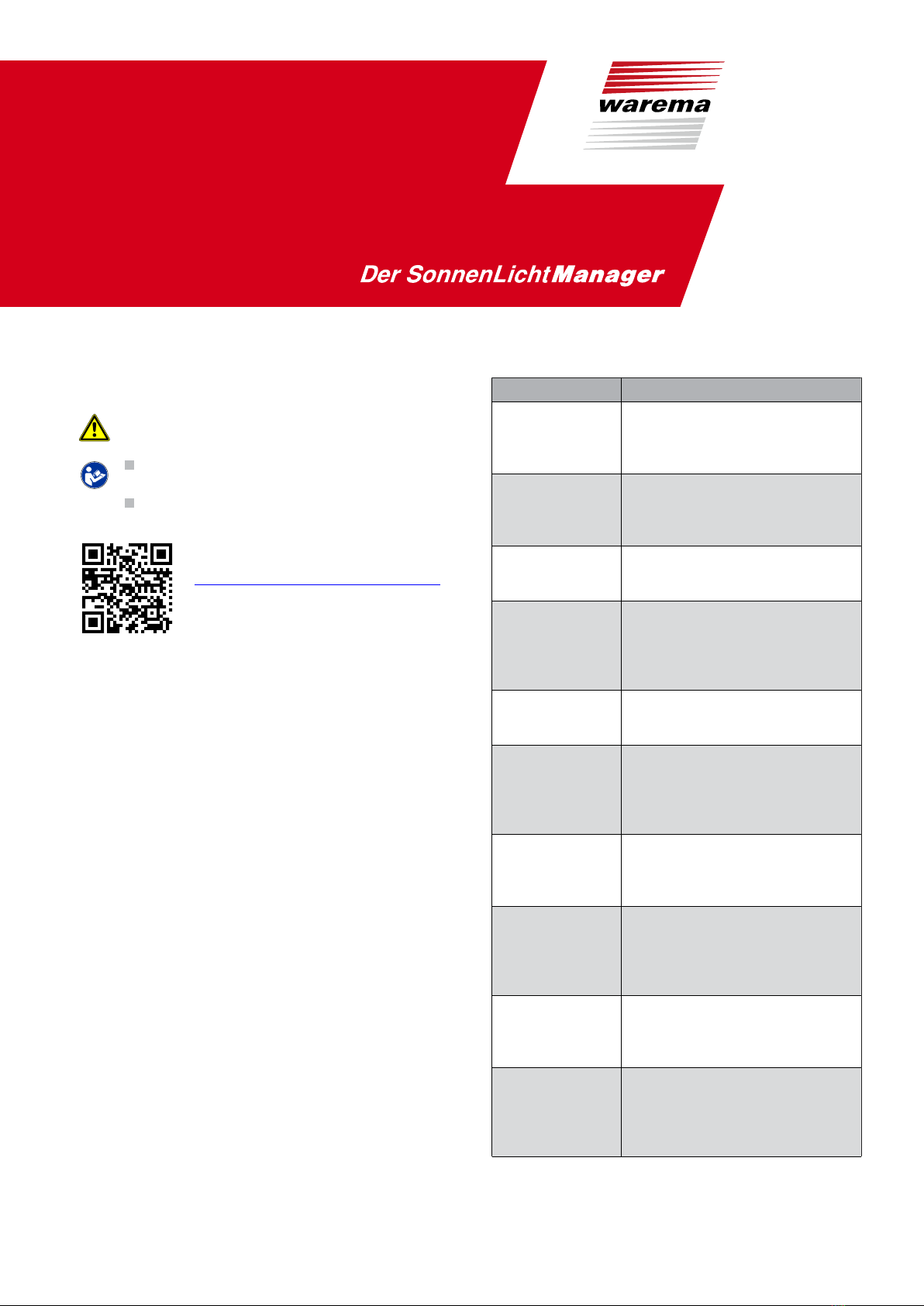
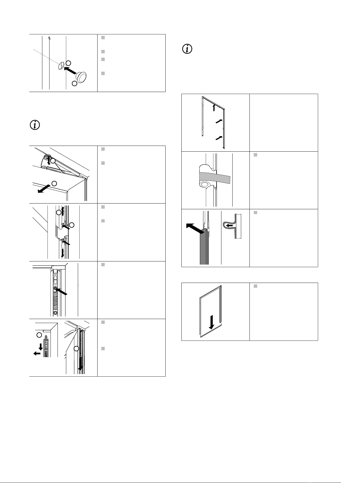
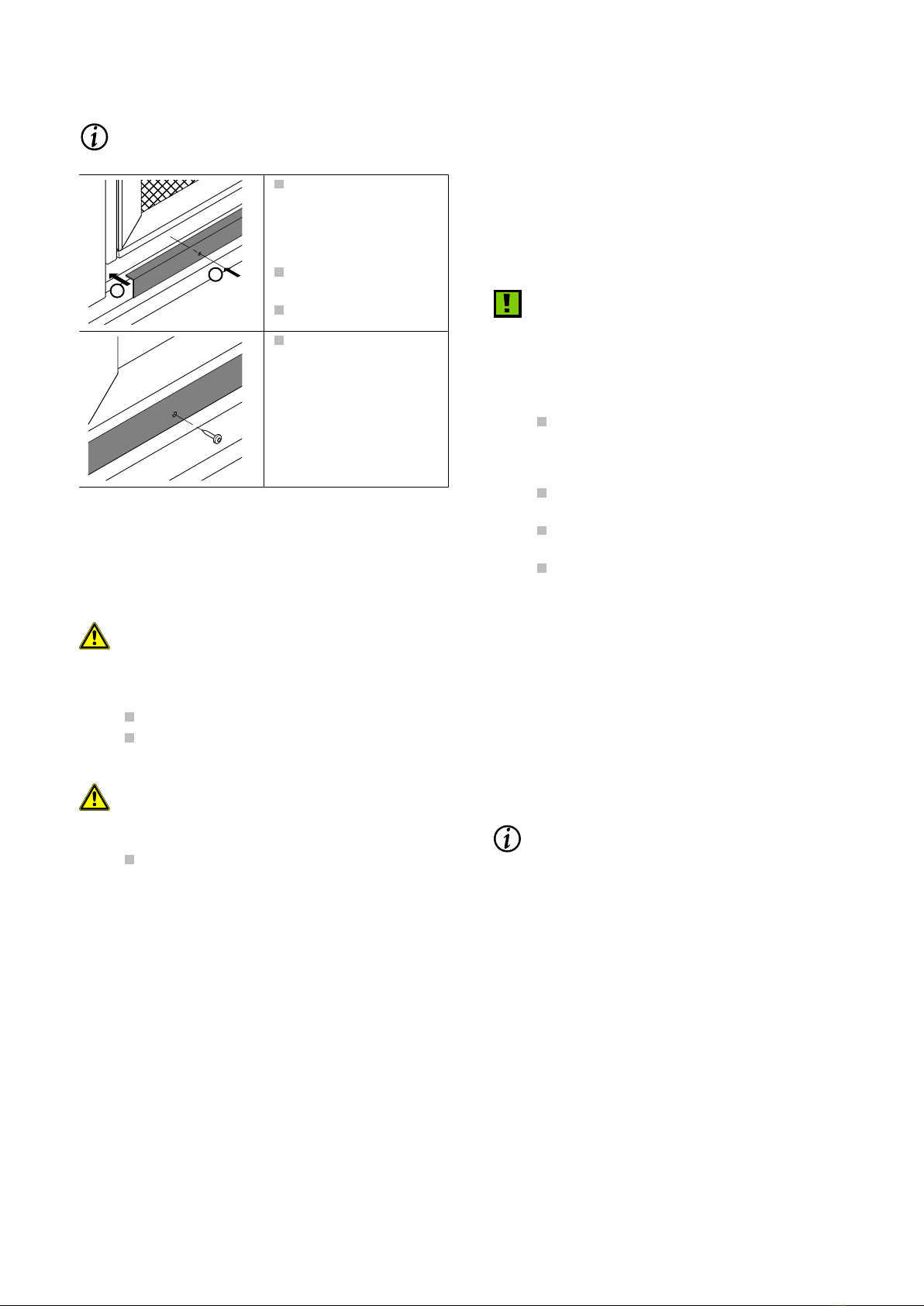
2.5 Installing the L-guide profile
INFO
Only required with P.50, P.51 and P.80.
1
2
Position the L-guide pro-
file below the swinging
door against the mount-
ing substructure and
align.
Transfer the drill hole
position.
Drill the fixing holes.
Attach the L-guide pro-
file.
3 Maintenance
Proper and regular cleaning and the use of original spare
parts only are essential for fault-free operation and a long
service life.
CAUTION
Risk of injury from falling from climbing aid!
Climbing aids (e.g. ladders, scaffolding etc.) may tip
over if improperly erected.
Position climbing aids on level and firm ground.
Do not rest climbing aids against the product.
CAUTION
Risk of injury from falling!
There is a risk of falling during maintenance work!
Take suitable, safe measures to prevent or stop a
fall!
3.1 Cleaning and care
Over time, a film of dirt will settle on the surfaces of
products due to environmental influences.
Due to the effects of solar radiation, this contamination may
become permanently adhered to the surface coating. These
factors reduce the value and, possibly, impair the function
of the product.
To contribute to a long service life of the product, the
surfaces should be cleaned regularly or at least once a
year.
In certain environments such as in industrial zones, close
to heavy traffic and in the vicinity of the sea (salty air), more
frequent cleaning may be necessary to protect against
surface damage.
Purpose of cleaning and care
The purpose of regular and proper cleaning and care is to
retain the value of the product and extend its service life.
The purpose of repeatedly cleaning the product is to retain
the well-maintained appearance of the building and product.
Result of cleaning
NOTICE
Product damage from incorrect cleaning!
Incorrect cleaning procedures may result in
damage to the product or product parts. Surfaces
and structures may be permanently altered (e.g.
scratches).
Do not use high pressure washers, steam
washers, abrasive sponges, abrasive cleansers,
or aggressive cleaning agents or solvents such
as alcohol or naphtha.
Do not use chlorinated cleaning agents on or
near the product.
Do not wash the insect screen gauze in a
washing machine or similar equipment.
Do not rub the fabric excessively with a hard
brush or sponge.
No claims for damage can be raised on the grounds of this
cleaning information, as the effectiveness depends on a
large number of factors that vary widely from case to case.
The effort required for cleaning and the cleaning results
depend on the degree of soiling. It will difficult or possible
to restore surfaces that have been exposed to the weather
and have not been cleaned over many years to their original
state.
General information on cleaning
Tip/recommendation
The WAREMA cleaning glove combined with
WAREMA cleaning agent concentrate for sun
shading products is ideal for properly cleaning the
surfaces.
The WAREMA cleaning agent can be used for metal
and plastic surfaces and is certified by the GRM
(Gütegemeinschaft Reinigung von Fassaden e.V.)
(certification no. 142, 242, 342, 442, 542).
To order, contact your WAREMA dealer.

Maintenance
Page 6 | 8 2023248 [Rev. 4 - en]/2018-05-04
For further advise and in technical
matters regarding cleaning,
please contact the Verband
Deutscher Sonnenschutzreiniger e.V.
(www.vds-sonnenschutz.de).
Preparing cleaning
When cleaning the product, protect adjacent areas
against soiling.
Aids required for cleaning:
Soft brush/duster (soft bristles)
Vacuum cleaner (optional)
Bucket
Low-calcium water (recommendation)
Cleaning agent (pH-neutral)
Microfibre cloth or sponge
Cotton cloth
INFO
Step-wise cleaning from top to bottom
1 Frame
2 Gauze
3 step profile/sash bar
Performing rough cleaning
Clean the complete product
of loose dirt (e.g. dust). A
soft brush or duster (with soft
bristles) can be used for this.
Alternatively, a moist microfibre
cloth or a moist sponge can be
used.
Performing detailed cleaning
Cleaner
Prepare the bucket with
water and cleaning agent.
Note the dosing quantities
specified by the cleaning agent
manufacturer.
Moisten the microfibre or
sponge.
Clean the product components
with a wiping motion. Repeat
the procedure if necessary due
to the degree of soiling.
Drying the product
INFO
To avoid calcium edges around dried water droplets,
the surfaces of the product can be rubbed dry using
a microfibre cloth or cotten cloth.
Inspecting the product during cleaning
Operate the product and inspect it for visible wear and
damage (visual check).
3.2 Maintenance
The product must be maintained at least once a
year.
The maintenance tasks may only be performed
by a qualified specialist. We recommend signing a
service contract.
The WAREMA warranty becomes invalid if the unit is
not maintained properly at least once a year.
INFO
To retain the warranty, maintenance must be
performed by a qualified specialist according to the
WAREMA maintenance checklist.
The maintenance checklist is available from
your specialist dealer or can be requested from
WAREMA.
3.3 Spare parts/repairs
INFO
To ensure that your product will operate properly
on a continuous basis and to avoid changing
its approved status, use original spare parts
only. Contact your WAREMA specialist dealer if
necessary.
3.4 Warranty
Subject to the statutory period of limitation for warranty
claims. This requires regular maintenance. The warranty
does not include wear parts or optical changes in line
with the type of material used (e.g. bleaching of surfaces
caused by UV rays).

2023248 [Rev. 4 - en]/2018-05-04 Page 7 | 8

WAREMA Renkhoff SE Hans-Wilhelm-Renkhoff-Straße 2 97828 Marktheidenfeld Germany
www.warema.com info@warema.com
This manual suits for next models
11
Table of contents