warequip Brewer Patient LiftMate User manual

INSTALLATION & OPERATION MANUAL
Component Identification......................................2
Important Information...........................................3
Specifications.........................................................4
Safety Information.................................................4
Electrical Requirements.........................................5
Installation.............................................................6
Operation...............................................................8
Maintenance........................................................ 11
Troubleshooting................................................... 11
Service Parts.........................................................14
Limited Warranty.................................................15

COMPONENT IDENTIFICATION

IMPORTANT INFORMATION
General
The Brewer LiftMate Patient Lift is designed to safely assist patients onto and off of exam tables, beds and other
medical devices without the need for manual lifting. The LiftMate is to
be operated by qualified medical professionals trained in its use. Read and understand all operating instructions,
safety information, and maintenance requirements contained in this manual prior to operating the LiftMate.
Become familiar with all of the LiftMate’s functions before using it with a patient.
The Brewer LiftMate Patient Lift is primarily used in examination rooms for safely lifting patients with mobility
issues onto exam tables. The LiftMate is easily operated with a hand
pendant. The platform height can be raised and lowered from 1” to 10”.
The LiftMate is easily moved from room to room on casters. The casters are extended by the operator when
moving the LiftMate is required. Casters are extended by pressing and holding the “Push And Hold To Move”
button. Once the LiftMate is in the desired position, releasing the “Push And Hold To Move” button will cause the
casters to retract. When the casters retract the LiftMate will be lowered, and rest on four rubber feet for stability.
NEVER ALLOW THE PATIENT
ONTO THE LIFTMAT E WITH THE CASTERS EXTENDED.
Once the casters have retracted and the LiftMate is resting on all four feet, the patient may then step onto the
platform. The patient then turns around so his/her back is toward the table. Once the patient is secure, the operator
can then raise the patient to a height where he/she can be seated. The operator can then either extend the casters to
roll the LiftMate away from the table, or LiftMate may be left in place depending on the type of exam and
physician’s preference.
When the examination is complete the LiftMate can be rolled back into position. Once the casters have retracted
and the LiftMate is resting on all four feet, the platform can be raised
to a height that is comfortable for the patient to step onto the LiftMate platform. NEVER ALLOW THE
PATIENT ONTO THE LIFTMAT E WITH THE CASTERS EXTENDED. Once the patient is on the LiftMate
the platform can then be fully lowered allowing the patient to easily step back onto the
floor.
To provide untethered mobility the LiftMate can be operated via battery power. However it is recommended that
the LiftMate be plugged into a 120VAC wall receptacle whenever
possible to maintain optimal battery power and life. Note: only plug the LiftMate into a receptacle capable of
providing a minimum of 4 amps of current. Some pieces of medical
equipment having auxiliary receptacles are not capable of providing enough power and will result in blown fuses.
See the “Battery” section of this manual for more information on
getting the most out of your LiftMate battery.
Orientation
Left and right orientation on the LiftMate are designated by how the patient approaches the unit to step onto the
platform. Front is the entry area, and back is the area that is positioned against the exam table. See Figure 2.
Service
If you require assistance with the installation or operation of your Brewer LiftMate Patient Lift, call Warehousing
Equipment Customer Service Department at 1800 337 711. Our trained staff will attempt to assist you in
correcting the problem directly over the phone. If service is required, a factory authorized technician will be sent to
your location.

Weight of LiftMate............................................... 105 lbs.
Load Rating (maximum):
- Platform.............................................................. 500 lbs.
- Platform Range......................................... 1.0 to 10.0 in.
LiftMate Dimensions:
Platform Width (Inside)..................................... 21 3/8 in.
Platform Depth (Inside)..................................... 18 1/4 in.
Distance Between Inner Shrouds....................... 24 1/4 in.
Distance Between Platform Handrails (Inner Surfaces).28
in.
Width Between Outer Shrouds.......................... 34 3/4 in.
Base Width (Outer)............................................ 31 3/4 in.
Base Depth (Outer)............................................ 21 1/2 in.
Mat Dimensions
Width.................................................................. 19 1/2 in.
Width........................................................................ 17 in.
Caster Dimensions
Diameter..................................................................... 2 in.
Width.......................................................................... 2 in.
Electrical Specifications
115 VAC nominal, 60 HZ, 4 amps max.
SPECIFICATIONS
Power Cord..............................Extends 10 ft. from unit.
18 AWG / 3 conductor, SJT grey jacketed with hospital
plug
Type of protection against electrical shock
Class............................................. Class II Double
Insulated
Type of protection against electrical shock………. B
Applied Parts
Certifications*
UL60601-1; IEC60601-1; CAN-CSA C22.2 No. 601.1
Battery Specifications
Type.............................................Sealed Lead Acid
Storage
Charging..........Battery is charged through Control Box
only
Temperature (Ambient Operating).......... 41°F to 104°F
Output...................................................... 24 V DC, 10A
Duty Cycle..... 2 minutes on/18 minutes off (motor run
time)
Operating Conditions
Temperature Range..................................65°F to 85°F
Relative Humidity....................................10% to 90%
Transportation and Storage
Temperature Range.................................-20°F to 150°F
Humidity...................................................10% to 90%
SAFETY INFORMATION
Safety Information
The primary concern of The Brewer Company
is that the equipment is operated and maintained
with the safety of the patient and healthcare
staff in mind. To ensure safe and reliable
operation:
●Read and understand all instructions in this
manual before attempting to install or operate
the unit.
●Ensure that appropriate personnel are
informed on the manual contents. This is the
responsibility of the purchaser.
●Ensure that this manual is located near the
LiftMate, or if possible permanently affixed to
the unit.
Failure to follow instructions with this symbol
could result in serious personal injury and/or damage
to the unit.
DANGER indicates an imminently hazardous
situation which, if not avoided, will result in death or
serious injury.
WARNING indicates a potentially hazardous
situation which, if not avoided, could result in death
or serious injury.
CAUTION indicates an imminently or potentially
hazardous situation which, if not avoided, may
result in serious injury and/or equipment damage

ELECTRICAL REQUIREMENTS
●Do not perform any procedures while
patient is on the LiftMate.
●Use 115 VAC, 60 Hz as noted on the rating
label. Failure to do so may result in electrical
shock to personnel and will result in damage
to the LiftMate.
●Do not use the LiftMate in an explosive or
oxygen enriched atmosphere. Failure to do so
may result in serious personal injury or death.
●Charging the battery with any device other
than through the Control Box on the unit may
result in serious personal injury, damage to
other LiftMate components, and/or premature
failure of the battery.
WARNING CAUTION
Do not use any power supply other than that listed on the
rating label. Failure to do so may result in serious injury
and/or equipment damage.
●●This product has been evaluated with respect to
electrical shock, fire, and mechanical hazards only in
accordance with UL60601-1; IEC60601-1; CAN/CSA
C22.2 No. 601.1
Electromagnetic Interference
This product is designed and built to minimize electromagnetic
interference with other devices; however, if interference is
noticed between another device and this product, remove the
interfering device from the room or plug this product into an
isolated circuit.
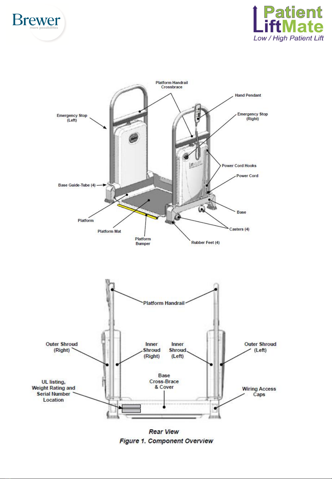
WARNING Never place any body parts
between the Handrail Crossbrace and Shrouds,
or under the
front edge of the Platform.
Both views show platform raised
WARNING Please observe the following
warnings (continued).
Do not allow more than one person on the LiftMate at a
time.
●Ensure that the back of the LiftMate is pushed as close to
the exam table as possible.
●●Make sure that all exam table drawers, stirrups,
attachments or other protrusions are pushed in to prevent
damage.
Children, Caregivers and Untrained Personnel:
●Anyone not trained in the safe use of the LiftMate must not
be allowed to operate it.
●Ensure that children and others are clear of the LiftMate at
all times whether it is being operated or not.
●Never allow the patient to operate the LiftMate at any time.
Special Patient Situations:
●The LiftMate must not be used by patients to pull
themselves up out of a wheelchair or walker.
●Do not use the LiftMate for patients that are unable to
support their own weight.
●Never exceed LiftMate’s maximum capacity of 500 lbs.
General: Please observe the following consideration.
●LiftMate must not be used to transport anything including
patients.
●If battery fails while casters are up or down, plug into
receptacle to recharge.
Patient and Operator: Ensure that loose
clothing, buttons, jewelry or other such items that
can snag onto the LiftMate are kept clear of catch
points
Patient:
●Never put a patient on the LiftMate while
casters are extended.
●Patient should only get on or off of the LiftMate
when all four base feet are firmly on the ground.
●Do not allow patients to pull themselves up by
using any part of the LiftMate.
●Patient must stand in the centre of the platform during the
lift procedure. Never lean forward, backward or sideways
beyond the area indicated by the dashed line.
WARNING Please observe the
following warnings.

CAUTION Please observe the following cautions.
Patient:
●Never engage casters while patient is on the LiftMate.
●Always use the top centre of the handrails for holding onto the LiftMate while getting on/off, or being raised or
lowered.
●Patients must use caution when stepping up to get onto the platform to avoid tripping.
●When patient is on table, ensure that the platform is lowered below patient’s feet before moving unit back to the
table for dismounting.
●Patient must be facing away from the exam table and holding onto the LiftMate’s handrails before raising the
platform.
●Lower platform when not in use to minimize risk of inadvertent contact and possible leg injury.
Special Patient Situations: Walkers and canes may be used to get onto the LiftMate, but must not be used during
lifting and lowering.
Power Cord: Always wind up power cord when not in use and during transport of LiftMate.
INSTALLATION
Unpacking
NOTE: Inspect all boxes and contents for damage.
Report
any damage to the carrier immediately.
CAUTION
●To avoid damaging the LiftMate’s plastic or
painted surfaces, DO NOT use a knife or other
sharp object to open the packaging.
●Lift only at points indicated in Figure 3. Do not
lift at other points.
●Do not plug LiftMate into receptacle prior to
removal of all packaging materials.
WARNING
The LiftMate weighs approximately 105 lbs. Two or
more people should assist in removing the Lift-Mate
from the shipping skid. Also, use proper lifting
techniques when lifting. Failure to do so could result
in serious injury.
CAUTION
Do not lift LiftMate at any point other than the lift
points indicated in Figure 3. Do not lift by shrouds,
power cords, or hand pendant cords. Serious damage
to the LiftMate, or personal injury may occur if
attempting to lift unit at an undesignated lift point.
1. Cut and remove banding from shipping carton.
2. Remove lid.
3. Separate and remove the two carton halves.
4. Remove foam packing blocks.
5. Remove plastic bags from platform handrails.
6. LiftMate weighs 105 lbs. Use two or more people
to lift unit from lower carton tray. Use caution to not
catch rubber feet on anything that may cause them to
detach.

INSTALLATION (Continued)
Getting the Most from the LiftMate Battery
NOTE: The LiftMate has protective circuitry to
prevent the
charge from draining to excessively low levels.
Keeping the battery charged will ensure optimal
service, while extending battery life to its fullest.
1. When the charge in the LiftMate battery drops to
a pre-set level the “Low Battery” indicator light on
the hand pendant will flash and the unit will beep
when the any button is pushed. Plug LiftMate into a
wall receptacle as soon as possible to recharge the
battery.
2. When the charge in the LiftMate battery drops to
a level that will cause battery life to shorten if use
continues, all functions will stop. The unit will beep,
and a steady indicator light on the hand pendant will
appear if any hand pendant button is pushed. Plug
LiftMate into wall receptacle to enable functions
and recharge battery.
3. Always use a replacement battery from Brewer.
Never use any other battery which could cause
damage to the unit or improper operation.
4. When not using the LiftMate, always keep the
unit plugged into a wall receptacle to keep the
battery charged. Leaving the unit unplugged for an
extended period of time (i.e. several months) will
allow the battery to discharge, causing premature
battery failure.
LiftMate Battery Disposal
CAUTION
●Do not disassemble the LiftMate battery.
●Please dispose of the LiftMate battery according to
your local regulations for lead-acid storage batteries

OPERATION
General
DANGER
Do not use the LiftMate in an explosive or
oxygenrich atmosphere. To do so will result in
an explosion or fire.
WARNING
If the LiftMate malfunctions, immediately
remove your hand from the controls, press one
of the “Emergency Stop” buttons, unplug the
power cord from the electrical receptacle, and
assist the patient from the unit. If LiftMate
continues to malfunction, call for service. Do not
attempt to repair LiftMate yourself.
WARNING
Keep personnel and equipment clear of LiftMate
before initiating movement to avoid personal
injury or damage to the equipment.
CAUTION
The hand pendant is moisture resistant and runs
on low voltage, eliminating shock hazards.
However, to avoid temporary or permanent
damage to the hand pendant, do not immerse in
water or liquids.
CAUTION
Keep foreign objects away from hand pendant.
To avoid accidental operation, be sure the hand
pendant is NOT positioned between the LiftMate
and any other object. Failure to do so could
result in unwanted motion and possible injury to
patient or operator, or damage to LiftMate or
exam table.
NOTE: For optimum LiftMate performance, allow the
unit to reach room temperature before operating.
NOTE: The LiftMate is not designed for continuous
operation.
The control system includes a thermal overload
safety switch to protect from overheating. If the unit is
operated continuously causing the control to exceed its
allowable operating temperature, the thermal overload
safety switch will shut off. If normal operation ceases,
do not attempt to operate the unit. Allow the unit to
cool for 10-15 minutes before attempting to use again.
The thermal overload switch will automatically reset
when it has reached a safe operating temperature.
NOTE: Each control function will automatically stop
moving when either the UP or DOWN travel limit is
reached. If the hand pendant is pressed with travel at
its limit, the actuator will not operate. Sensors prevent
the actuator motor from operating when travel limit
has been reached, preventing wear of the actuator.

OPERATION (Continued)
Moving the LiftMate
The LiftMate moves about easily on four
extendable/retractable casters.
To extend casters depress the “PUSH AND HOLD TO
MOVE” button on the hand pendant. See Figure 4.
Casters will extend allowing the LiftMate to be moved to
the desired location. The button must be held to keep
casters extended. Releasing the “PUSH AND HOLD TO
MOVE” button will cause casters to retract, lowering the
LiftMate onto the four base feet providing a stable unit for
the patient to step onto.
CAUTION
●Do not lower LiftMate onto wet, or slippery
surfaces, or onto objects that may cause imbalance
●Make sure operator and patients feet are clear of
unit before lowering.
●Make sure path of travel is free of obstructions
that may cause unit to tip.
Patient Handling with the LiftMate
(Positioning the LiftMate and raising the
patient)
1. Extend casters. Figure 5.
2. Position the back of LiftMate against foot end or side
of exam table. Figure 6.
3. When in position allow casters to retract by releasing
the button.
4. Assist patient by having them walk forward onto
LiftMate platform.
5. Once patient is on LiftMate assist them in turning
around so their back is toward exam table, and they are
grasping the platform handrail. Figure 7.
6. Press “UP” on the hand pendant to raise patient to the
height that is best for seating them. Figure 8.
7. Seat patient onto exam table.
8. Platform may be left in the “UP” position. To lower
platform press “DOWN” on the hand pendant, Figure 9
next page.
9. Note: LiftMate may be left in position at the foot end
of exam table, or moved out of the way depending upon
procedure or preference of clinician.

OPERATION (Continued)
Patient Handling with the LiftMate
(Lowering the Patient)
1. Roll the back of the LiftMate against foot end or side of
exam table, depending on position of patient on the table.
2. Ensure patient’s feet are clear of the platform and any
portion of the exam table as it is raised.
3. Make sure the platform is raised by pushing the “UP”
button, Figure 8.
4. Have patient slide forward to stabilize feet onto platform.
5. Patient can then come to a standing position on platform
and grasp handrail.
6. Lower platform all the way down, Figure 9, and assist
patient off of LiftMate.
Emergency Stops
Emergency Stops are located on the outer right-hand and outer left-hand Shrouds, Figure 10. In the unlikely
event of unintended movement of the Platform, depressing the Emergency Stop, Figure 11, will cause all
Platform movement to cease. Have a qualified technician inspect the unit prior to using. Rotating the Emergency
Stop Switch clockwise, Figure 12, will reset it to normal operation. Note: The Emergency Stops only deactivate
the Platform. The casters will still deploy with the Emergency Stop button depressed.

MAINTENANCE
Preventative Maintenance Cleaning
CAUTION
Failure to perform periodic inspections of the
LiftMate could result in personal injury or
equipment damage.
CAUTION
The shroud material is resistant to most medicinal
type stains, but may be damaged by solvents and
dyes. Remove any spilled fluids from the shrouds,
painted surfaces or mat immediately.
●Periodically inspect the electrical cord to ensure it
is free of cuts or damage.
●Inspect the mechanical functions to ensure
satisfactory operation.
●Ensure that cord hooks are not loose. Remove
outer right shroud and tighten if necessary.
●Check shroud screws to make sure they are present
and tightened securely.
●Check platform bumper for damage, and to ensure
that it is secured to the edge of the platform. Reattach
or replace as necessary.
●Make sure the covers located at the back of the
platform when raised, are engaged with the guides,
and move freely when the platform is raised up and
down.
●Clean the LiftMate weekly, wiping the painted metal
and plastic surfaces with a clean, soft cloth. If desired,
mild cleaners may be used.
●Clean the mat immediately after contact with any
fluids or gels. Use a mild soap and rinse with clear
water. Avoid the use of harsh chemicals as they can
permanently damage the finish. To prevent mat from
peeling do not allow it to remain wet.
TROUBLESHOOTING
Casters
All casters will not extend or retract. This may indicate a low battery condition. Pressing any function on the
Hand Pendant will cause “Low Battery” light on Hand Pendant to illuminate, and beeping sound to occur. Charge
battery. Note: plugging LiftMate into receptacle will resume all functions in a low battery condition. If this action
does not resume functionality contact Warehousing Equipment Customer Service at 1800 337 711.
One caster will not extend or retract. Contact Warehousing Equipment Customer Service at 1800 337 711.
Casters are difficult to roll. Lay LiftMate onto its back on a carpeted or protective surface that will not damage
the finish. Check casters for wear, debris or damage. Clean or replace as needed. See the Service Parts list for
replacement kit number.
Casters causing marks on floor. Over time casters can get embedded with dirt redepositing it onto flooring. Lay
LiftMate onto its back on a carpeted or protective surface that will not damage the finish. Clean casters with soap
and water. Use a fine stiff wire brush with just enough force to remove dirt (use only if necessary). Use this
opportunity to check casters for wear or damage. Replace as needed. See parts list for replacement kit number.

TROUBLESHOOTING (Continued)
Platform
Platform will not raise or lower
• Battery low. Pressing any function on Hand Pendant will cause “Low Battery” light on Hand Pendant to
illuminate and beeping sound to occur. Charge battery. Note: plugging LiftMate into receptacle will resume all
functions in a low battery condition.
• Emergency Stop button(s) pushed in. Turn both Emergency Stop buttons clockwise to unlock. Retry raising or
lowering platform.
• This may be due to lift actuators being out of sync. Reset LiftMate by performing the following steps. *Note:
when pressing two buttons simultaneously to perform a reset they must be pushed at exactly the same time. It may
take several attempts to initiate reset.
• If performing the above steps does not resume functionality contact Warehousing Equipment Customer Service
at 1800 337 711
• Press both the “UP” and “Down” buttons on the hand pendant simultaneously and hold for a 10 beep count
emanating from the LiftMate. When the10 beeps are complete, a second cycle of beeps with a longer pause
between them will emanate from the LiftMate. It is during this second cycle of beeps that the LiftMate platform
can be moved. Press the “Down” button on the hand pendant to ensure that it is lowering correctly. If it is lowering
correctly bring platform to its lowest position. LiftMate lift actuators are now in sync. Double check by raising
platform to its full up position.
Mobility
LiftMate will not roll
• Make sure to press and hold the “Push and Hold to Move” button on the hand pendant to keep casters extended
for mobility.
• Battery low. Pressing any function on Hand Pendant will cause “Low Battery” light on Hand Pendant to
illuminate, and beeping sound to occur. Charge battery. Note: plugging LiftMate into receptacle will resume all
functions in a low battery condition.
• If performing the above steps does not resume functionality contact Warehousing Equipment Customer Service
at 1800 337 711.

LiftMate Operates Only When Plugged In
A. If the battery’s ability to hold a charge has decreased over time, the battery requires replacement.
B. If battery has suddenly failed without warning the battery may have become disconnected. Remove the left
outer cover to check battery connection at the plug in jack. If the connection is tight, and the battery is still
inoperable, replace the battery.
LiftMate Fails to Operate Even When Plugged In
Sudden failure of all functions is indicative of no power at the wall receptacle or failure of the control box. Plug a
lamp or other device known to operate into the receptacle to ensure power is available. If no power is available
plug LiftMate into wall receptacle proven to have power. Check to see if LiftMate functions resume operation. If
problem persists, contact Warehousing Equipment Customer Service at 1800 337 711 for a replacement control
box.
Rubber Feet
The rubber feet are easily replaced. Lay LiftMate onto its back on a carpeted or protective surface that will not
damage the finish. Replace feet onto ends of legs by pressing all the way on and hold. A slight bump will
protrude from the centre of the foot. Pushing this bump in will cause the conical shaped catch on the inside of the
foot to hook into the receiving hole in the leg. If there is difficulty getting the catch to hook, a rounded device of
sufficient diameter (3/16”) or larger such as a ball end Allen wrench can be inserted into the hole and pushed in.
DO NOT USE A POINTED OR SHARP OBJECT SUCH AS A PHILLIPS OR FLAT BLADED
SCREWDRIVER. See the Service Parts list for replacement kit number.
Platform Mat
If the platform mat has become excessively soiled, worn or is peeling, replace with the Platform Mat
Replacement Kit. See the Service Parts list for replacement kit number.
Platform Bumper
If the platform bumper has detached it can be pushed back onto the edge of the platform. If the bumper will not
stay attached replace with the Platform Bumper Kit. See the Service Parts list for replacement kit number.
Other Troubleshooting
For all other troubleshooting please contact Warehousing Equipment Customer Service at 1800 337 711.
TROUBLESHOOTING (Continued)

SERVICE PARTS
All kits include applicable hardware and step-by-step instructions.
KIT NAME ORDER NO
DESCRIPTION
Rubber Feet 2102273 Set of (4) replacement feet for legs.
Casters 2102275 Set of (4) replacement casters .
Short Caster Actuator 2102277 One short caster actuator for right rear or left front casters.
Long Caster Actuator 2102279 One long caster actuator for left rear or right front casters.
Lift Actuator 2102281 Set of (2) lift actuators.
Power Cord 2102283 Replacement power cord that plugs into wall receptacle.
Power Cord Hooks 2102285 Set of (2) Hooks on right side of LiftMate that secure the power cord.
E-Stop Interface
Button 2102287 Red Button that attaches to the outside shroud. The emergency stop switch is inside the
unit and is connected to the other side of this button. Kit includes (1) button.
E-Stop Switch 2102289 The switch that is mated to the E-Stop button. The kit includes (1) switch. The switch
disconnects power to the lift actuators only.
Hand Pendant 2102291 Replacement hand pendant with strain relief and button graphics label attached.
Hand Pendant Hook 2102293 Hook for hanging hand pendant when not in use.
Back Cover 2102295 Sliding two piece cover that spans the gap between the platform and base.
Platform Mat 2102297 Slip resistant mat that covers the top of the platform.
Platform Bumper 2102299 Yellow rubber strip covering the front edge of the platform.
Right Outer Shroud 2102301 Right outside cover with power cord hooks and E-Stop button attached.
Left Outer Shroud 2102303 Left outside cover with E-Stop button attached.
Right Inner Shroud 2102305 Right inside cover.
Left Inner Shroud 2102307 Left inside cover.
Battery 2102309 Replaceable storage battery specifically designed for this unit.
Control Box 2102311 Control unit through which the power cord is connected and the battery is charged. The
hand pendant input and the lift and caster actuator outputs are connected as well. Lift
actuator synchronization and battery management is monitored through the control box.
E-Stop Wiring Harness 2102313 The wiring harness that connects to the E-Stop switches and allows power to operate the
lift actuators when switches are in their normal state.
L Caster Actuator
Harness 2102315 The wiring harness that brings power to the left caster actuators.
R Caster Actuator
Harness 2102317 The wiring harness that brings power to the right caster actuators.
L Lift Actuator
Harness 2102319 The wiring harness that brings power to the left lift actuator.
R Lift Actuator
Harness 2102321 The wiring harness that brings power to the right lift actuator.
Battery Wiring
Harness 2102323 The wiring harness that goes from the control box to a receptacle that the
battery plugs into. Charge current to the battery and power from the battery
travel through this harness.

1800 337 711
(03) 9314 6300
Sales Enquiries
Contact Information
Service and Spare Parts
service@warequip.com.au
Customer Service
customerservice@warequip.com.au
www.warequip.com.au
Table of contents
Other warequip Lifting System manuals