Warner Electric CBC-500 Series User manual

Installation Instructions
CBC-500 & 550 Series
Torque Adjustable Clutch/Brake Controls
P-239-24-WE
819-0486

2Warner Electric • 800-234-3369 P-239-24-WE
Contents
Introduction .................................2
Specifications ...............................3
Installation ..................................4
Control Adjustment ...........................4
Switching Options ...........................5
Dimensional Diagrams .........................6
System Troubleshooting .......................7
Declaration of Conformity ......................8
Mounting Templates .........................10
Warranty ...........................back cover
Failure to follow these instructions
may result in product damage, equipment damage,
and serious or fatal injury to personnel.
Introduction
Warner Electric’s CBC-500 and CBC-550 series clutch/
brake controls are compact units designed for operation
with Warner Electric 90VDC and 24VDC clutches and
brakes, includ-ing failsafe units. Dual channel torque
adjust-ment is provided via on-board potentiometers for
soft starts and stops as well as accurate release points
for failsafe designs. These con-trols can operate with
each channel either in dual or single mode. Dual or single
mode is con-trolled via an on board jumper for use in a
vari-ety of applications. A transformer is provided on the
CBC-550 series controls, extending the input AC voltage
range. Four models are available:
CBC-500-90 120 VAC input
CBC-500-24 24-30 VAC or VDC input
CBC-550-90 120/220/240/380/480 VAC input
CBC-550-24 120/220/240/380/480 VAC input
Three optically isolated inputs provide full flexi-bility
in interfacing customer supplied switching schemes.
Internal circuitry provides suppression of transients
during decay of the magnetic field to assure rapid cycle
rates. Two LED indicators are provided on the control
board for channel 1 and channel 2 indication.

Warner Electric • 800-234-3369 P-239-24-WE 3
Specications
Input:
CBC-500-90: 120 VAC ± 10%, 50/60 Hz, 1 phase, 250 VA max.
CBC-500-24: 24-30 VAC, 50/60 Hz, 1 phase; or 24-30 VDC, 250 VA max.
CBC-550-90: 120/220/240/380/480 VAC ± 10%, 50/60 Hz, 1 phase, 250 VA max.
CBC-550-24: 120/220/240/380/480 VAC ± 10%, 50/60 Hz, 1 phase, 250 VA max.
Output:
CBC-500-90: 0-90 VDC full-wave rectified nominal,
1.0 amp per channel max., 2.0 amps total
CBC-500-24: 0-24 VDC full-wave rectified nominal,
5.0 amps per channel max., 5.0 amps total
CBC-550-90: 0-90 VDC full-wave rectified nominal,
1.0 amp per channel max., 1.2 amps total
CBC-550-24: 0-24 VDC full-wave rectified nominal,
4.0 amps per channel max., 4.0 amps total
Circuit Protection: (fusing)
CBC-500-90: 2.5 amp, 250 V fast-blo, 3AG
CBC-500-24: 6.3 amp, 250 V fast-blo, 5 x 20 mm
CBC-550-90: 1.5 amp, 250 V fast-blo, 3AG
CBC-550-24: 5 amp, 125 V fast-blo, 5 x 20 mm
Switching Inputs: (external to control, supplied by customer)
Three optically isolated, 10-30 VDC:
Channel 1 Input (adjustable voltage applied to channel 1)
Channel 2 Input (adjustable voltage applied to channel 2)
Channel 2 Override Input (full voltage applied to channel 1)
Maximum off-state leakage < 1 mA
Adjustments:
Channel 1 Voltage (via potentiometer)
Channel 2 Voltage (via potentiometer)
Jumper (selects simultaneous or alternate mode)
Frequency Adjustment: 60-400 Hz (via potentiometer)
Ambient Temperature:
-20° to 122°F (-29° to 50°C)
Auxiliary Supply:
12 VDC, 250 mA maximum
Enclosure:
Optional NEMA 13 enclosure available

4Warner Electric • 800-234-3369 P-239-24-WE
1
1
2
3
4
5
6
7
1
2
3
4
5
6
7
8
8
1
1
2
2
2
3
3
3
4
4
4
5
5
5
6
6
6
7
7
8
8
POWER/SWITCHING
SWITCHING
CHANNEL 2 INPUT
(10-30 VDC)
CHANNEL 1 INPUT
(10-30 VDC)
CHANNEL 2 OVERRIDE INPUT
(10-30 VDC)
AUXILARY SUPPLY
+12 VDC, 250 mA
+
+
+
+
–
–
–
–
(Channel 2 LED) (Channel 1 LED)
CBC-500
WARNER ELECTRIC
480
VAC
CHANNEL 2
INPUT
(10-30 VDC)
CBC-550
WARNER ELECTRIC
OUTPUT
CHANNEL 2
(CLUTCH OR BRAKE)
CHANNEL 1
(CLUTCH OR BRAKE)
Factory
Connections
DO NOT USE
CHANNEL 2
(CLUTCH OR BRAKE)
CHANNEL 1
(CLUTCH OR BRAKE)
SPARE
SPARE
CBC-500-90: 120 VAC
CBC-500-24: 24 VAC or 24 VDC
CBC-500 Series
CBC-550 Series
+
+
+
+
–
–
–
–
–
+
–
+
–
+
–
+
HOT
AC
(Channel 2 Adjust) (Channel 1 Adjust)
Dual
Single
(Jumper)
on Bottom 4 pins - Alternat
on Top 4 pins - Dual Output
(Frequency Adjust)
POWER/OUTPUT
(Channel 2 LED) (Channel 1 LED)
(Channel 2 Adjust)
(Channel 1 Adjust)
Dual
Single
(Jumper)
on Bottom 4 pins - Alternat
on Top 4 pins - Dual Output
(Frequency Adjust)
0
VAC
380
VAC
240
VAC
220
VAC
120
VAC
- NEUTRAL
CHANNEL 1
INPUT
(10-30 VDC)
CHANNEL 2
OVERRIDE
(10-30 VDC)
AUXILARY
SUPPLY
12VDC
250 mA
Installation
The voltages present in this control can cause serious injury (even death). When installing
this control or any electrical equipment, make certain that the input power is off. Do not apply power to this
control until it is securely mounted and completely wired in accordance with local codes and all installation
work, including cleanup, has been completed.
Control Adjustments
Channel 1 and Channel 2 Torque Adjustment: Provides adjustment of 0 to full rated voltage.
Jumper: Allows operation of alternate or simultaneous mode of operation. In the single mode, Channel 1
and Channel 2 function in an alternate mode. In the dual mode Channel 1 and Channel 2 function
simultaneously. This mode will be employed in applications with a clutch and a failsafe brake. The control is
shipped with the jumper placed for the single mode of operation. To change to dual mode, carefully remove
the jumper and reinsert it on the dual side of the terminal block.
Frequency Provides adjustment of 60 to 400 Hz. This adjustment is simply to reduce the clutch/brake “hum”
Adjustment: associated with machine frequencies.
Connection Diagrams
CBC-500 Series
CBC-550 Series

Warner Electric • 800-234-3369 P-239-24-WE 5
1
2
3
4
5
6
7
8
12 VDC
CH2 Input
Ch1 Input
Ch2 Override
Out IN
+
+
-
CH2 Input
Ch1 Input
Ch2 Override
1
2
3
4
5
6
7
8
1
2
3
10
Clutch/Brake
Control
Out 1
Out 2
Out 3
GND
PLC
1
2
3
4
5
6
7
8
- +
20VDC
Power
Supply
No Connection
No Connection
CH2 Input
Ch1 Input
Ch2 Override
Clutch/Brake
Control
Clutch/Brake
Control
Switching Options
Option 1: External Power Supply
Option 3: PLC
Option 2: Internal Power Supply
Mode Options
Single Mode
Ch1 Ch2 Ch2
Ove
Ch1 output Ch2 output
0 0 0 No change No change
0 0 1 On at full torque Off
0 1 0 Off On at full torque
0 1 1 On at full torque Off
1 0 0 On at adjusted
torque Off
1 0 1 Full torque Off
1 1 0 On at adjusted
torque Off
1 1 1 Full torque Off
Dual Mode
Ch1 Ch2 Ch2
Ove
Ch1 output Ch2 output
0 0 0 No change No change
0 0 1 Off Off
0 1 0 On at adjusted
torque
On at adjusted
torque
0 1 1 Off Off
1 0 0 Off Off
1 0 1 Off Off
1 1 0 Off Off
1 1 1 Off Off
Note 1: In single mode, when power is applied to the
control, Ch1 comes on at adjusted voltage until a logic
input changes the output voltages.
Note 2: In single mode the control can not “turn off”
both channels at the same time; or “turn on” both
channels at the same time.
Note 3: When voltage is applied to “Ch2 override”, Ch2
and Ch1 logic inputs are ignored and the outputs are
changed to:
Ch1 = full torque and Ch2 = off.
When power is removed from “Ch2 override”, the control
reads the logic inputs and changes the voltage output
accordingly. If no power is applied to the logic inputs
when power is removed from Ch2 override, then the
output voltages remain at:
Ch 1 = full torque for Ch 1 and Ch2 = Off
Example:
Note 1: The minimum “on time” or “close time” of each
switch is 10m seconds.
Note 2: The switches in the above schematics can be
replaced with any kind of dry contact switches; or any
kind of relays. Examples: mechanical relays, momentary
contact switches, toggle switches, transistors, mosfets,
solid state relays, PLC outputs, etc.
Note 3: The logic inputs of the clutch/brake control are
optically isolated.

6Warner Electric • 800-234-3369 P-239-24-WE
Dimensional Diagrams
CBC-500 CBC-550
CBC-500
WARNER ELECTRIC
1.75"
0.90"
6.00"
0.20"
3.90"
1.15"
1.25"
1.40"
This control may be mounted on its base (two mounting slots) or on its back (four mounting slots).
Note: All dimensions nominal.
4.60"
2.85"
3.50"
4.72"
4.50"
4.08"
3.90

Warner Electric • 800-234-3369 P-239-24-WE 7
System Troubleshooting
The chart below will be helpful when attempting to isolate problems which may occur in the control system. It will also
prove helpful when encountering problems during initial system start-up.
Symptom A: No output on either channel upon power-up.
Probable Cause Solution
Improper wiring Check wiring and correct if necessary.
No power available Check that AC power is available to control.
Blown fuse See Fuse keeps blowing, Symptom C.
Symptom B: Channel 2 activates upon power-up.
Probable Cause Solution
Improper wiring Check wiring and correct if necessary.
Faulty input switching circuit Check that input switching network is providing proper signal.
Symptom C: Fuse keeps blowing.
Probable Cause Solution
Improper wiring Check wiring and replace fuse.
Shorted brake/clutch coil Check coil resistance and replace if necessary.
Fuse too small Replace with proper fuse.
Improper AC line voltage Check line voltage and correct if necessary.
Improper magnet voltage Check magnet voltage rating and replace with correct magnet if necessary.
Symptom D: Magnets do not appear to have enough torque.
Probable Cause Solution
Magnets incorrectly sized Verify sizing by repeating the selection process.
Symptom E: Outputs don’t switch; Inputs don’t switch.
Probable Cause Solution
Incorrectly wired inputs Check wiring and correct if necessary.
Faulty switching device Check for proper operation and replace if defective.
Faulty control Replace control.
Reorder Information
Model Part No.
CBC-500-90 6024-448-003
CBC-500-24 6024-448-002
CBC-550-90 6024-448-006
CBC-550-24 6024-448-005
CBC-500 Series Enclosure 6042-101-004
CBC-550 Series Enclosure 6006-101-007

8Warner Electric • 800-234-3369 P-239-24-WE
DÉCLARATION DE CONFORMITÉ
Nous: WARNER ELECTRIC
449 Gardner Street
South Beloit, IL 61080
déclarons sous notre seule responsabilité que les produits de la famille
CBC 500-90 &CBC 500-24
CBC 550-90 & CBC 550-24
sont uniquement destinés à l’intégration dans une machine. La mise en serv-
ice de ces produits est subséquente à l’homologation de l’ensemble de
l’équipmement, conformément à la directive 89/392/CEE.
La conformité des produits spécifiés ci-dessus avec les exigences de la direc-
tive 72/23/CEE est supportée par le respect des normes EN 61010-1.
Si les instructions de montage et de câblage du manuel sont respectées, ce
produit est conforme aux normes EN50081-1 et EN50082-1 directive
89/336/CEE relative à la CEM.
South Beloit, IL 61080
VP and General Manager: S. O.
Afin d’éviter des blessures,
s’assurer que toute puissance
soit coupée avant installation ou intervention sur ces
équipements.
NE PAS TOUCHER LE CIRCUIT ÉLECTRONIQUE, SI LA PUISSANCE
EST APPLIQUÉE.
INSTRUCTIONS D’INSTALLATION
ET DE CABLAGE
relatives à la CEM, directive 89/336/CEE
DES CONTROLES POUR EMBRAYAGES ET FREINS
1. L’ appareil doit être monté dans une armoire métallique close.
2. Liasion de puissance entre contrôle et embrayage/frein par cãble blindé.
3. Raccordements de consigne, entrées et sorties par cãbles blindés.
4. Les blindages sont reliés à la terre aux deux extrémités du cãble.
5. Les cãbles de commande et les cãbles de puissance ne seront pas placés
dans le mëme caniveau.
DECLARACION DE CONFORMIDAD
Nosotros: WARNER ELECTRIC
449 Gardner Street
South Beloit, IL 61080
declaramos bajo nuestra propia responsabilidad que los productos de la famil-
ia
CBC 500-90 &CBC 500-24
CBC 550-90 & CBC 550-24
son diseñados exclusivamente para incorporarse en otra maquina. El fun-
cionamiento de este producto esta sujeto al cumplimiento de todo el equipo
usado en la maquina, con los lineamientos de la norma 89/392/EEC.
El cumplimiento de los lineamientos de la norma 72/23/EEC con los productos
mencionados anteriormente, se basa y respeta los estandares EN 61010-1.
Si las instrucciones de montaje e instalación electrica del instructivo son
respetadas, este producto cumplirá con los estandares EN50081-1 y
EN50082-1 que se relacionan con la norma 89/336/EEC.
South Beloit, IL 61080
VP and General Manager: S. O.
Para evitar cualquier daño
personal, antes de intentar
instalar o reparar este control, siempre asegurese que
todas las fuentes de poder esten apagadas.
NO TOQUE EL CIRCUITO ELECTRICO SI LA FUENTE DE PODER
ESTA ENCEDIDA.
INSTRUCCIONES DE MONTAJE Y
CONEXIONES ELECTRICAS
en relación a la norma de EMC 89/336/EEC
PARA CONTROLES DE CLUTCHES Y FRENOS
1. El control debe de instalarse adentro de una caja metalica.
2. Las conexiones electricas entre el control y el cluch/freno DEBEN hacerse
con cable blindado.
3. Las conexiones de bajo voltaje en el control deben utilizar cables blinda-
dos.
4. El blindaje de los cables debe de aterrizarse en ambos lados.
5. Las conexiones entre la fuente de poder, y las conexiones de bajo voltaje
deben de hacerse en diferentes cables.
KONFORMITÄTSERKLÄRUNG
Wir: WARNER ELECTRIC
449 Gardner Street
South Beloit, IL 61080
erkälren in alleiniger Verantwortung, daß die Prdukte der Familie
CBC 500-90 &CBC 500-24
CBC 550-90 & CBC 550-24
ausschließlich zum Einbau in eine andere Maschine bestimmt sind. Die
Inbetriebnahme ist solange untersagt, bis die Konformität des Endproduktes
mit der Richtlinie 89/392/EWG gegeben ist.
Die Übereinstimmung des bezeichneten Produktes mit den Vorschriften der
Richtlinie 72/23/EWG wird nachgewiesen durch die Einhaltung der Normen EN
61010-1.
Sofern die Montage-Anweisungen der Bedienungsanleitung eingehalten wur-
den, ist dieses Podukt knoform zu EN50081-1 und EN50082-1 und die EMV
somit gewährleistet - Richtlinie 89/3366/EWG.
South Beloit, IL 61080
VP and General Manager: S. O.
Vor Einbau oder Wartung des
Gerätes unbedingt die
Stromversorgung unterbrechen um Verletzungen zu ver-
meiden.
KARTE BEI EINGESCHALTETER STROMVERSORGUNG NICHT
BERÜHREN.
MONTAGE UND KABELVERBINDUNGEN
ANWEISUNGEN
bezogen zu den EMW Richtlinic 89/336/EWG
FÜR STEURGERÃTE KUPPLUNGEN UND BREMSEN
1. Das Gerãt muß in einem gesclossenen metallschrank eingebaut werden.
2. Leistungsverbindungen Steuergerãte/Kupplungen - Bremsen mit
abgeschim Kabel durchfubren.
3. Steuerdeitungen, Ein-und Ausgãnge mittels abgeschimten Kabeln durch-
führen.
4. Abschirmung an beiden Enden des Kabels erden.
5. Leistungs-und Steuerverbindungen in separate Kabelkanãle durchziehen.
DECLARATION OF CONFORMITY
WE: WARNER ELECTRIC
449 Gardner Street
South Beloit, IL 61080
declare under our sole responsibility that the products of the family
CBC 500-90 &CBC 500-24
CBC 550-90 & CBC 550-24
are exclusively designed for incorporation in another machine. The operation of
the product is submitted to the conformity of the complete equipment, follow-
ing the provisions of the directive 89/392/EEC.
The conformity of the above specified products with the provisions of the
Directive 72/23/EEC is supported by the full respect of the standards EN
61010-1.
If the mounting and connecting instructions of the installation’s manual have
been respected, this product will be conform to the standards EN50081-1 and
EN50082-1 relating to the EMC directive 89/336/EEC.
South Beloit, IL 61080
VP and General Manager: S. O.
To avoid injury, always make certain all
power is off before attempting to install
or repair this control.
DO NOT TOUCH THE BOARD IF POWER IS APPLIED.
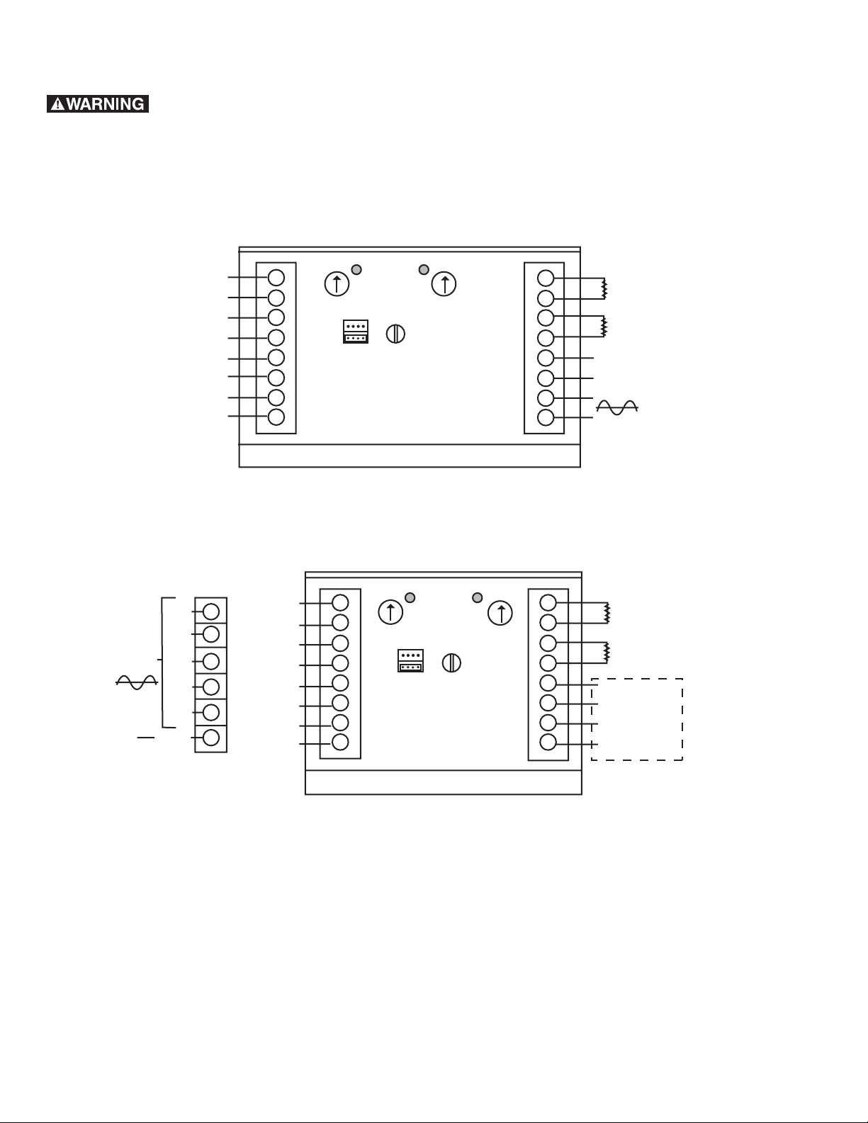
Mounting and Connecting Instructions
related to the EMC-directive 89/336/EEC
For Clutch and Brake Control
1. The control must be mounted in a closed metal cabinet.
2. The power connection between control and clutch/brake must be MADE
using shield cable.
3. The control connection must utilize shielded cables.
4. The shield of the cables must be grounded at both ends.
5. Power connections and control connection must be placed in separate
canals.
WARUNG:
ADVERTENCIA:
ADVERTISSEMENT:

Warner Electric • 800-234-3369 P-239-24-WE 9
Mounting Template for CBC-500
Mounting Template for CBC-550

Warranty
Warner Electric LLC warrants that it will repair or replace (whichever it deems advisable) any product
manufactured and sold by it which proves to be defective in material or workmanship within a period of one (1)
year from the date of original purchase for consumer, commercial or industrial use.
This warranty extends only to the original purchaser and is not transferable or assignable without Warner Electric
LLC’s prior consent.
Warranty service can be obtained in the U.S.A. by returning any defective product, transportation charges
prepaid, to the appropriate Warner Electric LLC factory. Additional warranty information may be obtained by
writing the Customer Satisfaction Department, Warner Electric LLC, 449 Gardner Street, South Beloit, Illinois
61080, or by calling 815-389-3771.
A purchase receipt or other proof of original purchase will be required before warranty service is rendered. If
found defective under the terms of this warranty, repair or replacement will be made, without charge, together
with a refund for transportation costs. If found not to be defective, you will be notified and, with your consent, the
item will be repaired or replaced and returned to you at your expense.
This warranty covers normal use and does not cover damage or defect which results from alteration, accident,
neglect, or improper installation, operation, or maintenance.
Some states do not allow limitation on how long an implied warranty lasts, so the above limitation may not apply
to you.
Warner Electric LLC’s obligation under this warranty is limited to the repair or replacement of the defective
product and in no event shall Warner Electric LLC be liable for consequential, indirect, or incidental damages of
any kind incurred by reason of the manufacture, sale or use of any defective product. Warner Electric LLC neither
assumes nor authorizes any other person to give any other warranty or to assume any other obligation or liability
on its behalf.
WITH RESPECT TO CONSUMER USE OF THE PRODUCT, ANY IMPLIED WARRANTIES WHICH THE
CONSUMER MAY HAVE ARE LIMITED IN DURATION TO ONE YEAR FROM THE DATE OF ORIGINAL
CONSUMER PURCHASE. WITH RESPECT TO COMMERCIAL AND INDUSTRIAL USES OF THE PRODUCT,
THE FOREGOING WARRANTY IS IN LIEU OF AND EXCLUDES ALL OTHER WARRANTIES, WHETHER
EXPRESSED OR IMPLIED BY OPERATION OF LAW OR OTHERWISE, INCLUDING, BUT NOT LIMITED TO,
ANY IMPLIED WARRANTIES OF MERCHANTABILITY OR FITNESS.
Some states do not allow the exclusion or limitation of incidental or consequential damages, so the above
limitation or exclusion may not apply to you. This warranty gives you specific legal rights and you may also have
other rights which vary from state to state.
Changes in Dimensions and Specications
All dimensions and specifications shown in Warner Electric catalogs are subject to change without notice.
Weights do not include weight of boxing for shipment. Certified prints will be furnished without charge on request
to Warner Electric.
P-239-24-WE 819-0486 6/19
www.warnerelectric.com
31 Industrial Park Road
New Hartford, CT 06057 - USA
815-389-3771
This manual suits for next models
5
Table of contents
Other Warner Electric Control System manuals