Waspper GP3300HA User manual

Operation Manual
EN
GP3300HA
Engine driven
Translation of the original operation manual
*The picture serves for reference only and it ay not represent an exact atch of the device delivered

1
INDEX
Application co pliant with the product design p. 1
Environ ental protection . . . . . . . . . . . . . . . . p. 1
Safety . . . . . . . . . . . . . . . . . . . . . . . . . . . . . . . p. 1
Scope of delivery . . . . . . . . . . . . . . . . . . . . . . p. 2
Asse bly . . . . . . . . . . . . . . . . . . . . . . . . . . . . p. 2
Co issioning . . . . . . . . . . . . . . . . . . . . . . . p. 3
Engine . . . . . . . . . . . . . . . . . . . . . . . . . . . . . . p. 4
Engine aintenance . . . . . . . . . . . . . . . . . . . p. 5
Pu p . . . . . . . . . . . . . . . . . . . . . . . . . . . . . . . p. 7
Troubleshooting . . . . . . . . . . . . . . . . . . . . . . . p. 9
Warranty. . . . . . . . . . . . . . . . . . . . . . . . . . . . . p. 10
Technical data . . . . . . . . . . . . . . . . . . . . . . . . p. 10
Declaration of confor ity in co pliance with EU standards . . . p. 12
CAUTION
Please read this operation anual carefully before the first use of your device and pay attention to the safety
instructions attached. Please obey these instructions at all ti es. Keep the operation anual for potential future
use or the next owner of the device.
Application co pliant with the product design
The use of this high-pressure washer is li ited to:
– in ho es and businesses where the achine running ti e does not exceed 5hours per week.
– washing of achinery, vehicles, structures, tools, facades, gardening tools, etc. co bined with a high-pressure
water supply (with added cleaning agents, wherever required);
– operation with accessories using spare parts approved by WPW Center s.r.o.
- In an environ ent where the device will not be exposed to direct splashing of conta inated water with solid
particles.
Environ ental protection
The packaging aterials are recyclable. Packaging disposal ethods ust co ply with the environ ent-friendly
principles.
Used achines contain valuable and recyclable aterials that can be reused. Any disposal of used achinery
ust be conducted in environ ent-friendly anner.
Any cleaning works producing waste water conta inated with oil, e.g. cleaning of engines or floors of achinery,
ay be only perfor ed in cleaning facilities provided with oil separating equip ent. Works with cleaning agents
are li ited to working areas with proper sealing to prevent leakage of fluids and linkage to the conta inated
water sewers. Make sure to avoid leakage of cleaning agents into water resources or soil.
Safety
Safety Instructions
Make sure you read the "Safety Instructions for High-Pressure Washers” in full prior to the first use of this
device.
Noise reduction tools and protective glasses should be used for the convenience of operators for
hearing and eye protection purposes during operation of the cleaner.

2
Hazard levels
DANGER - Indication of an i ediate danger potentially resulting in serious injuries or death.
CAUTION - Indication of a potential hazardous situation that ay result in light injuries.
WARNING - Indication of a potential hazardous situation that ay result in aterial da age.
Safety features
CAUTION - Safety features are designed to protect their users fro injuries and these ay not be altered
in any way or even put out of order
.
Any da aged ite s ust be replaced with original spare parts only.
Protective guards on hot or rotating parts
The protective guards are designed for protection of operators using the high-pressure washer to avoid injuries
caused by te peratures of certain co ponents of the co bustion engine or injuries caused by rotating parts of
the device.
Safety features on the co bustion engine and pu p
The engine oil level safety switch (if fitted) serves for auto atic deactivation of the engine in case the engine oil
level drops below the ini u threshold. That will prevent da age to the engine due to insufficient lubrication
of internal parts. However, this safety features does not substitute the need to check the engine oil level prior to
use of the device.
For further i portant infor ation see the section – ENGINE (p. 4).
The pu p safety valve serves for drainage of so e hot water developed during internal circulation of water
inside the pu p during operation without discharge of the high-pressure water.
Once the safety valve opens auto atically, so e of the hot water pours out of the pu p to be replaced with
cold water fro the connected supply. However, this safety feature does not substitute the need to switch the
pu p off when not in use for periods exceeds 2 inutes. For further i portant infor ation see the section –
PUMP (p. 7).
Scope of delivery
For depiction of delivery contents see the packaging or the purchase order. Check the contents co pleteness
when unpacking. Any ite s issing or any da ages incurred in transport should be notified to the seller.
Additional ite s required
Fabric-reinforced water hose with the dia eter of ½“ (13 ) with a regular garden quick-coupler.
The supply hose ust be at least 5 and at ost 15 long. The device ust be linked to an adequate water
resource with the ini u delivery pressure of 1 bar and the flow rate of 14 l/ in.
Asse bly
The device itself is asse bled in the anufacturing plant. Fix the upper fra e section - grip - onto the botto
part, by sliding it onto the narrowed part of the tube and use the flexible etal spring to lock it in place. (Figure
on page 3). Before connecting the hoses, re ove the covers fro the high-pressure water outlet and inlet on
the pu p. The first operation requires connection of the high-pressure hose, included in the delivery, with the
control gun and nozzle to the high-pressure section of the pu p.
The next step requires filling of the supplied oil into the engine, as directed by instructions in the section
ENGINE (p. 4) and filling the tank with fresh petrol with octane rating of 95.

3
Nut
Nozzle
Quick-coupler
The low-pressure inlet on the pu p ust be fitted with the garden hose adaptor, included in the delivery.
Co issioning
Water supply
CAUTION
Avoid operating the pu p without a water supply line connected and fed fro the source. The
water resource yield ust correspond with at least 14 litres per inute, at the ini u pressure of 1 bar. If the
purity of supplied water cannot be guaranteed, the syste needs a water filter placed before the pu p inlet to
avoid influx of solid conta inants inside the pu p.
Having connected the hoses, open the water tap fully to its li it position and depress the control lever on the
high-pressure gun. To deaerate the pu p hoses, keep the gun in depressed position until you observe an even
flow of water out of the quick-coupler. Insert the adaptor quick-coupler with the high-pressure nozzle.
If the
pump has not de eloped pressure within 30 seconds following its commissioning,
switch the engine off and proceed in compliance with instructions defined in the
Troubleshooting section! Any dry cycling of the pump for a period exceeding 30
seconds may result in damage!
Any aterial da age caused due to inobservance of this instruction renders the warranty void.
CAUTION WHEN USING SELF-PRIMING FUNCTION
For pu ps provided with the SELF-PRIMING
function:
The high-pressure washer and the filling hose fro
WPW Center (special accessories, catalogue nu ber SP000-HI001) can be used for re oval of surface water,
e.g. fro stor water reservoirs. The water in reservoir ust be clean, free of any conta inants or sludge.
Conta inated water causes irreversible da age to internal co ponents of the high-pressure pu p
.
Connect the hose to the filler neck directly (without the quick-coupler adaptor, included in the delivery). Make
sure the sealing between the hose and the pu p neck is free of any da age.
Sub erge the other end into the water reservoir. Re ove the nozzle fro the quick-release end of the high-
pressure gun attach ent so that the water spills out freely when the trigger is depressed. Start the engine and
depress the gun control lever to let the water flow out freely, until the strea co es out free of any air
bubbles. The ti e required to pu p water up to a continuous flow is proportional to the length of the inlet hose
and the height of the pu p in co parison to the water level. The longer the hose and the greater the height
difference, the longer the ti e it takes to pu p the liquid. The axi u height difference is 80c .
Once the syste has been bled, fit the nozzle and restart the engine again. The pu p is ready for operation
now. If the pu p has not developed pressure with the engine running for 30 seconds, switch the engine off and
proceed in accordance with instructions defined in the Troubleshooting section.

4
CAUTION: When air gets into the pump, it’s necessary to remo e the leaks and repeat
the whole process of bleeding the pump.
Engine
The engine
MUST
be filled with the correct a ount of engine oil supplied with the
delivery before its first co issioning. The bottle with engine oil may contain larger
amount than required for the particular engine type. For specifics refer to the
Technical data section. For easier cold engine start, we reco end reducing the
water outlet pressure according to the instructions on page 8.Set the pu p on a
horizontal surface. Open the oil su p plug, also fitted with the oil gauge. Fill the
engine with approxi ately
¾
of the oil a ount required. Screw the plug back into the
oil su p. With the
C
switch se to the
OFF
position (see the figure below), cycle the
engine by pulling the starter cord. Re ove the plug, wipe the gauge dry and check the
engine oil level.
CAUTION:
To get the correct reading, the gauge ust be fully screwed in place. Top
up the oil to achieve the final level between the MIN and MAX arks.
Re ove the plug and fill the tank with petrol carefully. To ensure full perfor ance of the engine, use fresh petrol
with the octane rating of 91 or higher. The physical properties of old and vapid petrol are different and it ay
cause an uneven run of the engine or reduced pu p perfor ance. Use clean and oil-free petrol only - your
engine is a four-stroke type.
DANGER
When in operation, the engine
produces carbon monoxide,
which is a colourless and odourless poisonous gas. Inhalation of carbon monoxide may cause nausea,
headaches, dizziness, omiting or e en death! The de ice may be used outdoors only, with proper
entilation ensured. It is also necessary to pre ent ingress of exhaust gases into enclosed rooms ia
unsealed openings. When working with the engine on, turn the de ice in such direction, where the
exhaust does not remain pointed at persons standing in the icinity or any opening in nearby structures
(garages, galleries, cellars, etc.). When in operation, the engine produces waste heat, resulting in heat-
up of arious engine components (exhaust, engine cylinder), which may cause serious burns. These
components may cause fire, when in contact with flammable materials.
DANGER
Petrol fumes are extremely flammable and explosi e substances that max cause burns, fire or e en
explosion, when handled improperly. Let the engine cool down for 5 minutes before adding petrol into
the tank. Then proceed with careful remo al of the tank lid and start pouring the petrol in with caution.
NEVER fill the fuel up to the rim, since petrol warms up during engine operation and swells, which may
result in leakage through the lid and subsequent explosion of fire. NEVER tip the high-pressure de ice
into such position, where petrol may leak from the tank. NEVER attempt to start the engine with damaged
components in the fuel supply, ignition or safety features.
The turn the engine switch
C
and the fuel switch
D
into the
ON (I) position.
Shift the speed control lever
B
into the position.
Shift the choke control lever
A
into the
CHOKE position.
Grasp the pu p grip with one hand fir ly and use the other
hand to hold the starter cord grip.
Pull the starter cord to the point, where you feel resistance
fro the engine. Then pull the grip sharply to prevent recoil. If
the engine fails to start on the first atte pt, depress the gun
and relieve the water pressure in a safe direction. Then repeat
the starting process by pull the starter grip again.

5
CAUTION! The starter cord recoil (engine
resistance against the direction of starter cord pull)
will draw your shoulder and hand towards the engine
faster than you are able to release is, this ay result
in spraining, contusion or breakage of your li b.
Once the engine has started up, shift the choke control lever
A
into the
RUN position SLOWLY.
ENGINE SHUTDOWN
Engine shutdown comprises the following steps
Shift the engine speed control lever (page 4)
B
to ½ of the turn towards the position and let the engine
run for at reduced speed for 15-20 seconds. Then proceed with turning the engine ignition switch
C
and the
fuel switch
D
into the
OFF position.
CAUTION The engine is fitted with the engine oil level sensor (not every odel though) to
switch the engine off, when the engine oil drops to hazardous point. This function does not
substitute the regular inspection of engine oil le el. Disregard to the regular inspections
ay result in irreversible da age to internal co ponents of the engine. Such da age is not
covered by the warranty.
NEVER spray any water on the engine when hot. Such actions ay cause ingress of water
into the fuel syste or the ignition syste . Clean the engine with a da p cloth and
co pressed air to re ove dust fro the air filter co part ent.
MAINTENANCE
Every 8 hours or every
day
Engine oil level check
Inspection of air filter and exhaust vicinity
After the first 5 hours
Engine oil change
Every 50 hours or at
the end of the season
Clean the air filter
Engine oil change
Every 100 hours
Inspection and adjust ent of the ignition spark plug electrode.
Fuel pipeline check
There ay be rare cases, when the protective etal guards co e loose during operation. These parts need to
be tightened, since long-ter exposure of a loose guard to vibrations causes da age to the ounting holes. If
da aged, the protective guard on the exhaust, the air filter or the cooling fan ust be replaced with original
spare parts, since that is the only way to ensure axi u operation safety.
Spare parts are available fro the anufacturer or any authorised servicing centre. For a co plete list of
co ponents, see this anual or the anufacturer’s website.
Storage for winter season
Correct long-term storage methods are essential to ensure smooth operation during
the next season. Correct storage helps extend the engine ser ice life.
The following steps will help you ensure the axi u service life of engine co ponents with protection against
corrosion and wear of sliding co ponents of the engine.
The engine ust be stationary and its te perature ust be below 50°C. Use a da p cloth to clean the engine
fro dust and dirt. Once dried up, any potential da aged spots ust be treated with paint or a piece of cloth
soaked up with oil. That will prevent entry of air to the etal sheet and subsequent corrosion.
Open the fuel tank cap and check the quantity of fuel inside the tank. Long-ter presence of fuel inside the tank
during storage has an adverse effect on the fuel quality. That ay cause an uneven operation of the engine and
a reduced perfor ance. Using the drain plug located on the botto side of the carburettor, drain all petrol fro
the tank and the carburettor.
DO NOT TIP THE ENGINE OVER.

6
THERE IS AN OIL LEAKAGE HAZARD! It is recommended to change the engine oil at
the end of the season. That will extend the engine ser ice life.
Engine oil change
It is reco ended to change the engine
oil after use of this equip ent
(according to
the Maintenance Schedule)
.
Switch the engine off. Let
the device cool down for a while, so its te perature
drops below 50°C. This will prevent potential burns. The
engine should re ain war still.
War oil drains
fro the engine ore easily.
- Unscrew the OIL PLUG WITH GAUGE.
- Place a container with the ini u capacity of 1 litre
below the drain plug.
- Loosen the drain plug carefully.
- Let the oil drain s oothly into the prepared container.
- Once the oil stopped draining, tip the engine to the side
slightly to let the re aining oil out too.
- Clean the surroundings of the drain plug and re-tighten the drain plug in its place again.
- Used engine oil needs to be deposited at one of the authorised collection points.
Engine oil is
hazardous waste!
Fill the engine with the correct a ount and type of engine
oil. For engine oil specifications, see below.
- For specific filling volu es refer to the Technical data
section.
- Set the pu p on a horizontal surface.
Fill the engine with approxi ately
¾
of the oil a ount
required. Screw the plug back into the oil su p. With the
engine operation switch in the
OFF
position, cycle the engine
by pulling the starter cord. Re ove the plug, wipe the gauge
dry and check the engine oil level.
CAUTION:
To get the correct reading, the gauge ust be
fully screwed in place. Top up the oil to achieve the final level
between the MIN and MAX arks.
Engine oil specifications
Engine oil is one of the factors influencing the perfor ance and service life of
the engine.
The ini u require ents for engine oil are: Viscous grade 10W30 or 10W40 with the quality rating of SF or
higher (SG, SH, SJ).
Use of engine oil grade
10W30
at a bient te peratures exceeding
27°C
ay result in higher oil
consu ption. The engine oil level therefore requires ore attention, when operating the device at such a bient
te peratures using the engine oil grade
10W30
.
It is reco ended to use oil grade
10W40 with the quality rating
of
SF or higher (SG, SH, SJ).
The engine oil included in the delivery exceeds the ini u quality require ents highly and it will ensure safe
operation of the engine with ini u wear of their internal co ponents under de anding operating conditions.
When topping up the engine oil, use the type and brand of oil already matching the
existing filling. Mixing of different oil types is not recommended!

7
Pu p
Your pu p features an all- etal fra e to ensure its long service life and flawless operation. The pu p contains
rotating parts ounted in very precise housings. It is therefore INEVITABLE that water fed into pu p
re ains free of any echanical conta inants. These conta inants would grind the contact surfaces inside the
pu p to increase the play between its internal co ponents and reduce the output pressure.
DANGER
The pump generates
a ery high pressure
at the outlet, making
the outlet water jet destructi e to soft items. IT IS PROHIBITED to point the water stream at
humans or animals. Disrespect to this warning may result in de astating effects leading to
permanent blindness, incised wounds, amputation or e en death.
CAUTION
High pressure may cause damage to soft and sensiti e objects. It is not recommended to use a high-
pressure jet in a close proximity to clean rubber or tires, glass, cohesion less arnish, plasters or wood.
Too strong water jet may alter the surface texture and result in permanent change of surface finishes.
In case of any doubts, it is recommended to test the effect of pressurised water jet on a sample, where
the potential alteration of surface texture has no impact on the operability or appearance of the particular
object.
Setting the jet further from the surface of object being washed will reduce the pressure generated by
water impact and alle iate the aggressi e washing effect. On the other hand, proximity of the jet to the
surface will increase the washing performance of water on the particular surface.
The water inlet neck is provided with a safety screen. The screen requires
regular inspections with respect to potential conta ination or da age.
Deposited conta inants will reduce the flow of water supplied, further
resulting in reduced washing perfor ance.
The screen ust be replaced with a new one IMMEDIATELY, when
da aged.
Mechanical damage of internal components of the pump
due to water contamination is not co ered by the
warranty!
The check al e serves for draining of a s all volu e of hot water
fro the pu p without any intervention by its operator in order to protect
the pu p fro overheating. There is no overheating hazard during
regular operation, since the pu p is fed with a constant supply of cold
water to ensure its cooling at the sa e ti e. The process of excessive
heat-up starts, while the engine is still on and the high-pressure gun is off
and there is no water jet co ing out of the nozzle. The pu p will switch
to the internal water circulation ode auto atically. The constant
circulation of water continues, until the te perature has reached the point
for check valve to drain a s all a ount of hot water in order to ensure
infeed of cold water to cool the pu p down. That is why the temperature
of water fed into the pump is limited to 40°C only. If the pressure
washer is to re ain idle for ore than a few inutes, it should be
switched off to prevent excessive load on the check valve and pu p.
When using the self-priming water supply mechanism:
Make sure the water inside the supply contained is placed as high as possible, when co pared to the water
supply into the pu p. Higher elevation difference of water levels helps to si plify the pri ing and reduce
cavitation - the pheno enon associated with release of air bubbles fro the liquid. That ay happen inside the
pu p, if the vacuu at the inlet is too high - i paired pri ing. There is a risk of da age to the pu p.
That is why the priming hose should ha e the largest diameter possible and it must be
the shortest possible. Follow the methods defined on page 3 to bleed to priming pipe.

8
Preparing the pump for operation
The pu p is filled with operating oil. Due to the changes in oil te perature during operation and ther al
expansion, a DISCHARGE VALVE is located on the upper side of the container. In order to avoid oil leaks fro
the pu p during the transport, the valve opening is closed with a sealant with an identification label. THIS
SEALANT NEEDS TO BE REMOVED BEFORE THE FIRST USE!
In Figure A, the sealant is
located on the vent valve.
After re oving the
sealant, a hole ust be
visible on the valve as
shown in Figure B. To
check the oil level, place
the pu p in the
horizontal position.
Otherwise, the level
recorded won’t
correspond with reality. The oil level ust be within the required
range during operation to secure thorough lubrication of internal co ponents. The oil level can be checked on
the pu p control slide (Figure C). It ust be located around the ark in the iddle. The second option is to
unscrew the plug with vent hole (Figure B) and check the oil level on the gauge (Figure D). The oil level ust
be between the arks shown in Figure D.
If it’s necessary to
pump the oil in the
pump, use only the
following grade oil:
80W90 GL5. Don’t
exceed the
maximum oil le el!
This can result in
damage to shaft
seals and oil leaks
from the pump.
Output water pressure control
This pu p allows the water outlet pressure to be
controlled within the range of 80 bar to 230 bar. To
change the pressure, slightly turn the controller on the
pu p (Figure E). The rule is: When looking fro above,
by turning TO THE RIGHT (clockwise), the pressure
decreases and turning TO THE LEFT, the pressure
increases. Increasing pressure also increases the engine
load and fuel consu ption. Therefore, it’s appropriate to
adjust the water pressure according to the specific
situation. By reducing the pressure, you can extend the
life of the engine and the pu p.
Pump maintenance
Replace the pump oil after e ery 50 hours of operation. Replace with 80w90 GL5 oil. Drain the oil fro the
pu p by releasing the plug located on the botto of the pu p. Once the old oil is drained, check the seal and
screw the plug back into the pu p cover - tighten. Pour the oil slowly through the vent plug and check the
level on the inspection slide. Once the required oil level has been reached, screw the vent plug back into the
pu p housing.
B
C D
E

9
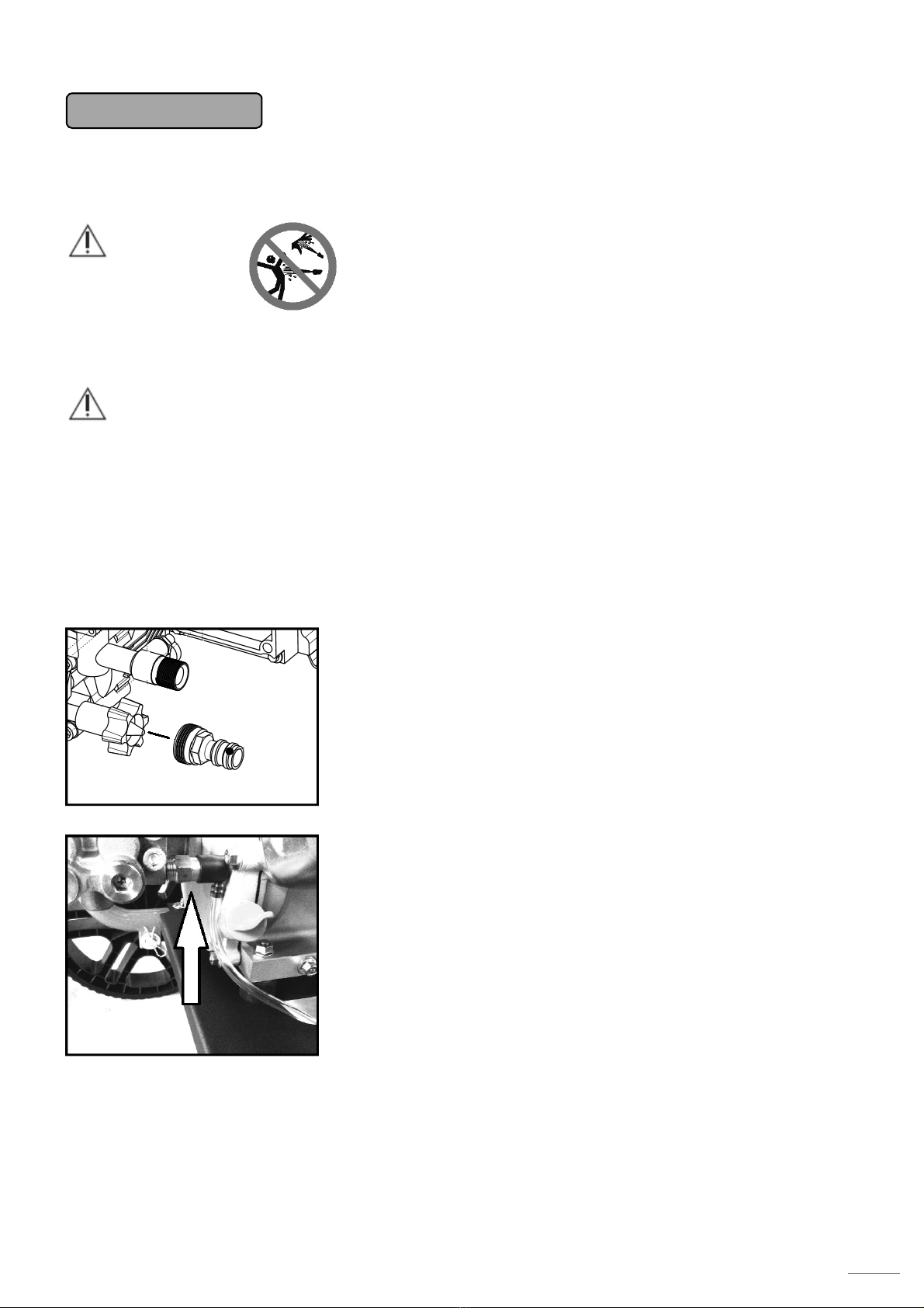
Use of self-priming cleaning agent
The pu p has a function for auto atic drawing of the cleaning agent
fro its supply contained using vacuu . The use of this function requires
Black nozzle for cleaning agent application (ite No.: SBS0-N0065). The
pu p will start drawing the cleaning agent through the opening arked
with an arrow, only when this nozzle is used. Link the cleaning agent
supply hose to the flange arked with an arrow (close to the high-
pressure pu p adaptor) and dip the other end with the screen into the
contained with diluted cleaning agent. Press the gun trigger to apply the
cleaning agent. This configuration is not designed for
production of acti e foam. Should you wish to use the active
foa , you need to purchase the foa generator (ite No.: SP000-FL002).
Pu p storage for winter season
Storing the pump in areas with the ambient temperature below the freezing point may
result in irre ersible damage to internal components, if not drained properly!
Excess water draining procedure:
Make sure the engine switch (p. 4 pos. C) is in the OFF position.
Disconnect the supply hoses fro the pu p. Grasp the starter cord grip and pull the cord 5 times, as if you
were starting the engine. This action will help the water drain out of the pu p through the high-pressure opening.
It is not reco ended to store the pu p in areas with the a bient te perature dropping below the freezing
point, since a significant change of outside te perature ay result in condensation of water vapour even in
areas regularly not affected by water ingress. That ay result in internal corrosion and a ore significant
reduction of the service life of pu p and engine.
Troubleshooting
Problem Cause Remedy
The pu p fails to generate
sufficient water pressure,
the water jet is inter ittent
and the water flow is low
1.
Nozzle with a large opening used
2.Blocked water supply
3.Low volu e of water supply
4.Clogged screen on water supply line
5.Clogged or leaking high-pressure hose
6.Supply water te perature too high
7.Water pressure leakage fro the gun
8.Clogged nozzle
9.Da aged pu p
10. I proper pri ing of pu p during the
self-pri ing ode
1.Replace it with a nozzle of the correct size
2.Check free water flow
3.Use a higher water pressure or a hose of
larger diameter
4.Clean the screen or replace it with a new
one
5.Remove contaminants, turn the hose
around, flush it or replace it with a new hose
6.Procure a supply of colder water
7.Check the connections for tightness, replace
the gun
8.Clean the nozzle with a steel wire and flush
it with flowing water
9.Contact a servicing centre
10. Check all the connections on the inlet side
for tightness, prime the pump as instructed
(page 4)
The pump fails to draw the
cleaning agent
1.Wrong nozzle used
2.The priming hose is not dipped in the cleaning
agent or it is clogged
3.Clogged hose or strainer
1.Replace the high-pressure nozzle with a
low-pressure (black) one
2.Check the volume of cleaning agent and
adjust the position of hose
3.Clean the washer with flowing water,
replace the priming hose
The engine runs smoothly
when not loaded, jerky under
load
1.Low engine speed
2. Water pressure too high
1. djust the position of speed control
lever,
check the position of locking screw for engine
speed control
2. Reduce the water outlet pressure by the
pump controller as described on page 8.
The engine stopped during
operation
1.The engine has run out of fuel
2.The spark plug terminal has fallen out
3. Low oil level in the engine
1. dd fuel into the tank
2.Check the spark plug terminal
3. Check the engine oil level

10
The engine fails to start or
starts and runs in jerky way
1.Clogged air filter
2.The engine has run out of fuel
3.Old fuel
4.The spark plug terminal is not linked with the
spark plug
5.Faulty spark plug
6.Fuel contaminated with water
7.Incorrect fuel mixing rate
1.Clean the air filter
2. dd fuel into the tank
3.Replace the fuel with fresh one or even top
up a larger amount of fresh fuel
4.Check the fittings of terminal on the spark
plug
5.Replace the spark plug with a new one
6.Drain the fuel from tank and carburettor
and add fresh fuel
7.Contact a servicing centre
Insufficient engine
performance
1.Clogged air filter
2.Old fuel
1.Clean the air filter
2.Fill the tank with a fresh fuel
Use original parts only. That will ensure smooth operation of your device.
Warranty
The warranty conditions of our distribution organisation apply in every country. Potential failures of your devices
will be re oved free of charge within the warranty period, if due to defects of aterial or work anship. To clai
the warranty, please sub it the sales receipt for your device at your distributor or the closest authorised servicing
workshop. For the list of approved servicing centres, see our website at: www.wpw-center.com
The efforts ade by WPW Center s.r.o. are ai ed at sustainable develop ent of technical para eters and
user-friendly para eters of its products. For this reason, the anufacturer reserves the right to alter the design
and control features without any prior notification to the end custo ers. The position of all control and safety
features illustrated in this anual corresponds with their actual positioning. This anual does not have to reflect
any changes in design of control levers.
Technical data
Device type
W3000HA
Engine type
Peggas 196c 3/
4,1
kw
Maxi u speed
3600 rp
Engine odel
Four
-
stroke OHV
Torque
1
2,4
N / 2500 rp
Ignition spark plug Brisk: LR14YC
spacing 0.7
-
0.8
Cha pion: RN7YC
NGK: BPR7ES
Fuel tank capacity
3.6 l
Oil filling capacity
0.6 l / 10w40
Water pressure and flow 3300psi/ 230bar
9
.5 l/ in.
Net weight
27.
5
kg
Height
95 c
Width
52c
Length 57c
Water pri ing function
Yes
-
80c

11
List of co ponents
Top fra e section - grip
Pressure hose
High-pressure nozzle
Hose bracket
High-pressure gun
Tank
Air filter
Gun adaptor with quick-coupler
Exhaust
Engine
Engine bracket
Botto section of fra e with chassis
Flexible grip locking pin

12
EU Declaration of Confor ity
The co pany WPW Center s.r.o. hereby declares that the high-pressure washers defined below
co ply with the relevant EU directives on occupational health and safety of the device operators.
Any alteration of the device without the prior consent fro the anufacturer will render this
declaration void.
Product details: High-pressure washer
TYPE Inspection reports Noise level
easured
Guaranteed noise
level
GP3300HA 2617/3/2017-02 100dB 102dB
Certificate issued by: TECHNICKÁ INŠPEKCI a.s., pracovisko KOŠICE, ako akreditovaný inšpekčný orgán
v zmysle EN ISO/IEC 17020
Applicable EU Directi es:
2006/42/ES (+2009/127/ES)
2004/108/ES
2000/14/ES
Standards applied:
STN EN ISO/IEC 17 020
Producer:
WPW Center s.r.o., Radlinského 20, 05201 Spišská Nová Ves, Slovensko
Issued in: Spišská Nová Ves Manufacturer's representative: Dobroslava Šupolová
Issue date: 1.8.2017 Position: Managing Director

13
Warranty Certificate
Product type:
Stamp and signature:
Serial nu ber: Date of purchase:
In pursuit of service enhancement and simplification of communication with customers, the company WPW Center s.r.o. recommends
its customers, who purchase this product, to register their product via the manufacturer's website: www.waspper.com. This
registration will provide inevitable data for faster processing of your complaints or consulting relevant to purchasing of spare parts and
accessories. This registration enables the customer to avoid further procedures, as submitting of the purchase receipt or the warranty
certificate.
1. The manufacturer - WPW Center s.r.o. - is liable for inherent defects of the product purchased, if such defects become evident within
the warranty period. pplication of claims for repairs under warranty requires completion and submission of the complaint form via
the manufacturer's website: www.waspper.com. The product is covered by a full warranty of 24 months for private customers (as
defined by the Civil Code) and 12 months for corporate customers (as defined by the Commercial Code). The warranty period
commences upon completion and submission of the complaint report via the website in case of simple defects and damages. The
commencement of warranty in case of major defects starts upon the product delivery to the manufacturer's address: WPW Center
s.r.o, Radlinského 20, 05201 Spišská Nová Ves. cceptance of complaint will be notified to the customer using the contact details
entered in the complaint form.
2. The warranty does not cover defects incurred due to: wrong operation; improper handling or use contradictory to the operation
manual or instructions and recommendations from the company WPW Center s.r.o; use or storage of goods within inappropriate areas,
especially with respect to temperature, dust formation or ambient humidity; exposure to direct sunlight; damage attributable to
natural disasters of force majeure. The warranty does not apply to mechanical damages, any damages due of solid particles, frost or
other weather effects. The warranty does not apply to damage to the pump caused by cavitation. Other exemptions from warranty
include damages to the engine due to lack of oil and ingress of any other but operating fluid among internal engine components.
3. Particular steps of claims processing will be notified to the customer following assessment of the scope of repair by the claims
engineer. Whenever the replacement of a damaged component can be performed by the customer, the latter will receive a relevant
spare part only. If the repair by a servicing centre is inevitable, the customer is obliged to mail the damaged device to the
manufacturer's address. The device must be complete (including accessories) and packed properly to prevent its damage during
transport, it must be free of mechanical damage and contain no operating fluids. If the goods submitted to the servicing centre shows
evident signs of damage or excessive wear, the manufacturer reserves the right to reject such consignment without acceptance.
4. Claims for repairs under warranty oblige the customer to provide the receipt of purchase (invoice, cash receipt) together with the
warranty certificate and written description in support of their claim, including photographic documentation. It is recommended to
complete the complaint form via the manufacturer's website to ensure the fastest processing of the claim as possible, if the
manufacturer acknowledges such claim as justified, the repaired item will be sent to the customer and the postage/freight will be
covered by the manufacturer.
5. If the claims engineer finds out the product does not comply qualifications for repair under warranty, the claim will be considered
unjustified and the costs of product transport to the customer will be paid by the latter.
6. Should the repair period exceed 30 days or if the product is irreparable, the customer will be offered a replacement item.
7. Justification of claims will be assessed by the claims engineer at the manufacturer. Justified claims will extend the warranty period
by the period taken by the claim processing period. Such action will be confirmed to the customer by means of a document in writing,
dispatched together with the product or sent via e-mail. If the product subject to claim contains any discontinued component, the
manufacturer will provide the customer with an adequate replacement item with its parameters corresponding with the returned
product or even better.
8. The customer undertakes to read all the information found on the packaging or in the operation manual; to do so immediately
following the product delivery, to acknowledge that preservation of the positive characteristics of the product delivered will be subject
to its proper operation and storage. ny disregard to obligations defined herein relieve the company WPW Center s.r.o. from any
liability for defects of goods or damages incurred due to breach of this obligation by the customer or any other third party. The
customer is obliged to check the intact condition of packaging and product during the purchase and takeover of the consignment from
the postman. ny damage to the packaging must be reported to the carrier and recorded immediately. ny damages found only after
unpacking of the product must be notified to the distributor within the maximum period of 4 working days. No later claims for product
damage can be accepted.

14
Preparation of the device before the first start!
Check the oil level in the engine
Engine is oil-free from
production!
Unscrew the oil plug with a gauge
and pour the engine oil supplied with
the cleaner. Pour 0.6L oil into the
engine. Screw the plug back into the
engine. Re ove the plug and check
whether the level is between the L
and H arks.
Preparing the pump for operation
The pu p is filled with operating oil. Due to the changes in oil te perature during operation and ther al
expansion, a DISCHARGE VALVE is located on the upper side of the container. In order to avoid oil leaks fro
the pu p during the transport, the valve opening is closed with a sealant with an identification label. THIS
SEALANT NEEDS TO BE REMOVED BEFORE THE FIRST USE!
In Figure A, the sealant is
located on the vent valve.
After re oving the sealant,
a hole ust be visible on
the valve as shown in
Figure B. To check the oil
level, place the pu p in
the horizontal position.
Otherwise, the level
recorded won’t correspond
with reality. The oil level
ust be within the required range during operation to secure thorough lubrication of internal co ponents. The
oil level can be checked on the pu p control slide (Figure C). It ust be located around the ark in the iddle.
The second option is to unscrew the plug with vent hole (Figure B) and check the oil level on the gauge (Figure
D). The oil level ust be between the arks shown in Figure D.
If it’s necessary to
pump the oil in the
pump, use only the
following grade oil:
80W90 GL5. Don’t
exceed the
maximum oil le el!
This can result in
damage to shaft
seals and oil leaks
from the pump.
High pressure nozzle selection
Select the desired Nozzle. The
following rule applies: Wider spray
angle = larger area of the slide –
weaker washing effect. Insert the
nozzle into the end of the stainless
steel piston rod by pulling the ends
outer ring toward the pistol.
B
C D

15
Table of contents
Other Waspper Pressure Washer manuals
Popular Pressure Washer manuals by other brands

Kärcher
Kärcher K 4.86 M operating instructions

Kärcher
Kärcher K 395 M Operator's manual

Generac Power Systems
Generac Power Systems The Reliable Ones 1800PSI owner's manual

Yamakoyo
Yamakoyo GPW2700 PSI owner's manual

GreenWorks
GreenWorks GPW1804CK quick start guide

Craftsman
Craftsman HORSEPOWER 580.75231 owner's manual