Waspper W3000HC User manual

Operation Manual
EN
W3000HC
Engine driven
Translation of the original operation manual
*The picture serves for reference only and it may not represent an e act match of the device delivered

1
INDEX
Application compliant with the product design p. 1
Environmental protection . . . . . . . . . . . . . . . . p. 1
Safety . . . . . . . . . . . . . . . . . . . . . . . . . . . . . . . p. 1
Scope of delivery . . . . . . . . . . . . . . . . . . . . . . p. 2
Assembly . . . . . . . . . . . . . . . . . . . . . . . . . . . . p. 2
Commissioning . . . . . . . . . . . . . . . . . . . . . . . p. 3
Engine . . . . . . . . . . . . . . . . . . . . . . . . . . . . . . p. 4
Engine maintenance . . . . . . . . . . . . . . . . . . . p. 5
Pump . . . . . . . . . . . . . . . . . . . . . . . . . . . . . . . p. 7
Troubleshooting . . . . . . . . . . . . . . . . . . . . . . . p. 8
Warranty. . . . . . . . . . . . . . . . . . . . . . . . . . . . . p. 9
Technical data . . . . . . . . . . . . . . . . . . . . . . . . p. 9
Declaration of conformity in compliance with EU standards . . . p. 11
CAUTION
Please read this operation manual carefully before the first use of your device and pay attention to the safety
instructions attached. Please obey these instructions at all times. Keep the operation manual for potential
future use or the ne t owner of the device.
Application compliant with the product design
The use of this high-pressure washer is limited to:
– private households only;
– washing of machinery, vehicles, structures, tools, facades, gardening tools, etc. combined with a high-
pressure water supply (with added cleaning agents, wherever required);
– operation with accessories using spare parts approved by WPW Center s.r.o.
- In an environment where the device will not be e posed to direct splashing of contaminated water with solid
particles.
Environmental protection
The packaging materials are recyclable. Packaging disposal methods must comply with the environment-
friendly principles.
Used machines contain valuable and recyclable materials that can be reused. Any disposal of used machinery
must be conducted in environment-friendly manner.
Any cleaning works producing waste water contaminated with oil, e.g. cleaning of engines or floors of
machinery, may be only performed in cleaning facilities provided with oil separating equipment. Works with
cleaning agents are limited to working areas with proper sealing to prevent leakage of fluids and linkage to the
contaminated water sewers. Make sure to avoid leakage of cleaning agents into water resources or soil.
Safety
Safety Instructions
Make sure you read the "Safety Instructions for High-Pressure Washers” in full prior to the first use of this
device.Noise reduction tools and protective glasses should be used for the convenience of operators for
hearing and eye protection purposes during operation of the cleaner.

2
Hazard levels
DANGER - Indication of an immediate danger potentially resulting in serious injuries or death.
CAUTION - Indication of a potential hazardous situation that may result in light injuries.
WARNING - Indication of a potential hazardous situation that may result in material damage.
Safety features
CAUTION - Safety features are designed to protect their users from injuries and these may not be altered in any
way or even put out of order. Any damaged items must be replaced with original spare parts only.
Protective guards on hot or rotating parts
The protective guards are designed for protection of operators using the high-pressure washer to avoid injuries caused
by temperatures of certain components of the combustion engine or injuries caused by rotating parts of the device.
Safety features on the combustion engine and pump
The engine oil level safety switch if fitted) serves for automatic deactivation of the engine in case the engine oil level
drops below the minimum threshold. That will prevent damage to the engine due to insufficient lubrication of internal
parts. However, this safety features does not substitute the need to check the engine oil level prior to use of the device.
For further important information see the section – ENGINE p. 4).
The pump safety valve serves for drainage of some hot water developed during internal circulation of water inside the
pump during operation without discharge of the high-pressure water.
Once the safety valve opens automatically, some of the hot water pours out of the pump to be replaced with cold water
from the connected supply. However, this safety feature does not substitute the need to switch the pump off when not in
use for periods exceeds 2 minutes. For further important information see the section – PUMP p. 7).
Scope of delivery
For depiction of delivery contents see the packaging or the purchase order. Check the contents completeness
when unpacking. Any items missing or any damages incurred in transport should be notified to the seller.
Additional items required
Fabric-reinforced water hose with the diameter of ½“ (13 mm) with a regular garden quick-coupler.
The supply hose must be at least 5 m and at most 15 m long. The device must be linked to an adequate water
resource with the minimum delivery pressure of 1 bar and the flow rate of 12 l/hr.
Assembly
The device itself is assembled in the manufacturing plant. Fi the upper frame section - grip - onto the bottom
part, by sliding it onto the narrowed part of the tube and use the fle ible metal spring to lock it in place. (Figure
on page 3). Before connecting the hoses, remove the covers from the high-pressure water outlet and inlet on
the pump. The first operation requires connection of the high-pressure hose, included in the delivery, with the
control gun and nozzle to the high-pressure section of the pump.
The ne t step requires filling of the supplied oil into the engine, as directed by instructions in the section
ENGINE (p. 4) and filling the tank with fresh petrol with octane rating of 95.

3
Nut
Nozzle
Quick-coupler
The low-pressure inlet on the pump must be fitted with the garden hose adaptor, included in the delivery.
Commissioning
Water supply
CAUTION Avoid operating the pump without a water supply line connected and fed from the source. The
water resource yield must correspond with at least 12 litres per hour, at the minimum pressure of 1 bar. If the
purity of supplied water cannot be guaranteed, the system needs a water filter placed before the pump inlet to
avoid influ of solid contaminants inside the pump.
Having connected the hoses, open the water tap fully to its limit position and depress the control lever on the
high-pressure gun. To deaerate the pump hoses, keep the gun in depressed position until you observe an
even flow of water out of the quick-coupler. Insert the adaptor quick-coupler with the high-pressure nozzle. If
the pump has not developed pressure within 3 seconds following its
commissioning, switch the engine off and proceed in compliance with instructions
defined in the Troubleshooting section! Any dry cycling of the pump for a period
exceeding 3 seconds may result in damage!
Any material damage caused due to inobservance of this instruction renders the warranty void.
CAUTION WHEN USING SELF-PRIMING FUNCTION
For pumps provided with the SELF-PRIMING function: The high-pressure washer and the filling hose from
WPW Center (special accessories, catalogue number SP000-HI001) can be used for removal of surface
water, e.g. from storm water reservoirs. The water in reservoir must be clean, free of any contaminants or
sludge. Contaminated water causes irreversible damage to internal components of the high-pressure pump.
Fill the filling hose with water up to the rim to eliminate any air bubbles inside.
Connect the hose to the filler neck directly (without the quick-coupler adaptor, included in the delivery). Make
sure the sealing between the hose and the pump neck is free of any damage.
Submerge the other end into the water reservoir. Remove the nozzle from the quick-coupler on the end of
high-pressure gun adaptor. Start the engine and depress the gun control lever to let the water flow out freely,
until the stream comes out free of any air bubbles. Once the system has been bled, fit the nozzle and restart
the engine again. The pump is ready for operation now. If the pump has not developed pressure with the
engine running for 30 seconds, switch the engine off and proceed in accordance with instructions defined in
the Troubleshooting section.
CAUTION If the pump draws air in, the whole deaerating procedure must be repeated.

4
Engine
The engine MUST be filled with the correct amount of engine oil supplied with the
delivery before its first commissioning. The bottle with engine oil may contain larger
amount than required for the particular engine type. For specifics refer to the
Technical data section.
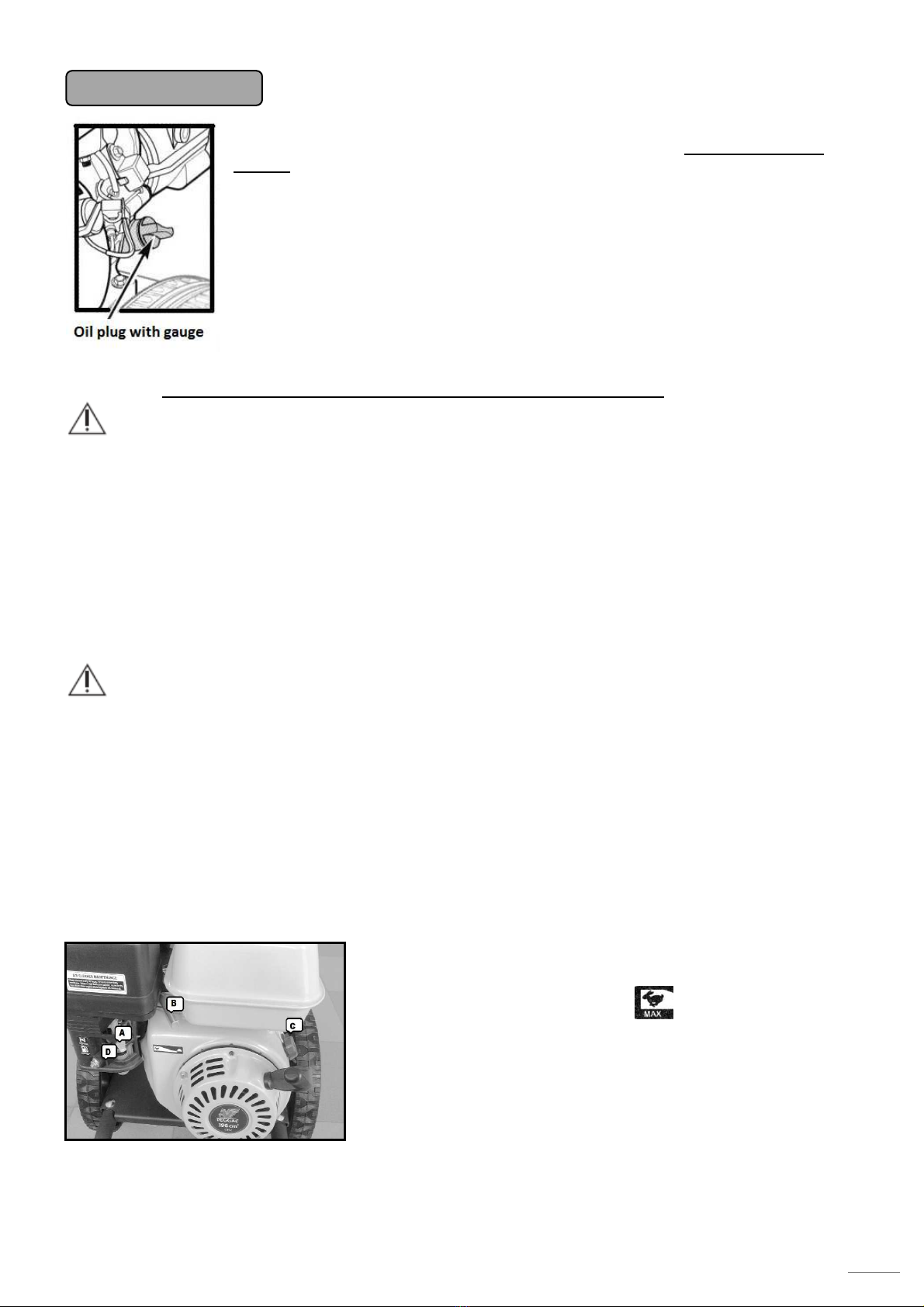
Set the pump on a horizontal surface. Open the oil sump plug, also fitted with the oil
gauge. Fill the engine with appro imately ¾ of the oil amount required. Screw the
plug back into the oil sump. With the C switch se to the OFF position (see the figure
below), cycle the engine by pulling the starter cord. Remove the plug, wipe the gauge
dry and check the engine oil level.
CAUTION: To get the correct reading, the gauge must be fully screwed in place.
Top up the oil to achieve the final level between the MIN and MAX marks.
Remove the plug and fill the tank with petrol carefully. To ensure full performance of
the engine, use fresh petrol with the octane rating of 91 or higher. The physical
properties of old and vapid petrol are different and it may cause an uneven run of the engine or reduced pump
performance. Use clean and oil-free petrol only - your engine is a four-stroke type.
DANGER
When in operation, the engine produces carbon monoxide, which is a colourless and
odourless poisonous gas. Inhalation of carbon monoxide may cause nausea, headaches,
dizziness, vomiting or even death!
The device may be used outdoors only, with proper ventilation ensured. It is also necessary
to prevent ingress of exhaust gases into enclosed rooms via unsealed openings.
When working with the engine on, turn the device in such direction, where the exhaust does
not remain pointed at persons standing in the vicinity or any opening in nearby structures
(garages, galleries, cellars, etc.).
When in operation, the engine produces waste heat, resulting in heat-up of various engine
components (exhaust, engine cylinder), which may cause serious burns. These components
may cause fire, when in contact with flammable materials.
DANGER
Petrol fumes are extremely flammable and explosive substances that max cause
burns, fire or even explosion, when handled improperly.
Let the engine cool down for 5 minutes before adding petrol into the tank. Then
proceed with careful removal of the tank lid and start pouring the petrol in with
caution. NEVER fill the fuel up to the rim, since petrol warms up during engine
operation and swells, which may result in leakage through the lid and subsequent
explosion of fire. NEVER tip the high-pressure device into such position, where
petrol may leak from the tank.
NEVER attempt to start the engine with damaged components in the fuel supply,
ignition or safety features.
The turn the engine switch C and the fuel switch D into the ON
(I) position.
Shift the speed control lever B into the position.
Shift the choke control lever A into the CHOKE position.
Grasp the pump grip with one hand firmly and use the other hand
to hold the starter cord grip.
Pull the starter cord to the point, where you feel resistance from the
engine. Then pull the grip sharply to prevent recoil. If the engine
fails to start on the first attempt, depress the gun and relieve the
water pressure in a safe direction. Then repeat the starting process
by pull the starter grip again.

5
CAUTION! The starter cord recoil (engine
resistance against the direction of starter cord pull)
will draw your shoulder and hand towards the
engine faster than you are able to release is, this
may result in spraining, contusion or breakage of
your limb.
Once the engine has started up, shift the choke control lever
A into the RUN position SLOWLY.
ENGINE SHUTDOWN
Engine shutdown comprises the following steps
Shift the engine speed control lever (page 4) B to ½ of the turn towards the position and let the engine
run for at reduced speed for 15-20 seconds. Then proceed with turning the engine ignition switch C and the
fuel switch D into the OFF position.
CAUTION The engine is fitted with the engine oil level sensor (not every model though) to
switch the engine off, when the engine oil drops to hazardous point. This function does
not substitute the regular inspection of engine oil level. Disregard to the regular
inspections may result in irreversible damage to internal components of the engine. Such
damage is not covered by the warranty.
NEVER spray any water on the engine when hot. Such actions may cause ingress of water
into the fuel system or the ignition system. Clean the engine with a damp cloth and
compressed air to remove dust from the air filter compartment.
MAINTENANCE
Every 8 hours or every
day Engine oil level check
Inspection of air filter and e haust vicinity
After the first 5 hours
Engine oil ch
ange
Every 50 hours or at
the end of the season Clean the air filter
Engine oil change
Every 100 hours Inspection and adjustment of the ignition spark plug electrode.
Fuel pipeline check
There may be rare cases, when the protective metal guards come loose during operation. These parts need to
be tightened, since long-term e posure of a loose guard to vibrations causes damage to the mounting holes. If
damaged, the protective guard on the e haust, the air filter or the cooling fan must be replaced with original
spare parts, since that is the only way to ensure ma imum operation safety.
Spare parts are available from the manufacturer or any authorised servicing centre. For a complete list of
components, see this manual or the manufacturer’s website.
Storage for winter season
Correct long-term storage methods are essential to ensure smooth operation during
the next season. Correct storage helps extend the engine service life.
The following steps will help you ensure the ma imum service life of engine components with protection
against corrosion and wear of sliding components of the engine.
The engine must be stationary and its temperature must be below 50°C. Use a damp cloth to clean the engine
from dust and dirt. Once dried up, any potential damaged spots must be treated with paint or a piece of cloth
soaked up with oil. That will prevent entry of air to the metal sheet and subsequent corrosion.
Open the fuel tank cap and check the quantity of fuel inside the tank. Long-term presence of fuel inside the
tank during storage has an adverse effect on the fuel quality. That may cause an uneven operation of the
engine and a reduced performance. Using the drain plug located on the bottom side of the carburettor, drain
all petrol from the tank and the carburettor. DO NOT TIP THE ENGINE OVER.

6
THERE IS AN OIL LEAKAGE HAZARD! It is recommended to change the engine oil at
the end of the season. That will extend the engine service life.
Engine oil change
It is recommended to change the
engine oil after use of this equipment
(according to the Maintenance Schedule). Switch the
engine off. Let the device cool down for a while, so its
temperature drops below 50°C. This will prevent
potential burns. The engine should remain warm still.
Warm oil drains from the engine more
easily.
- Unscrew the OIL PLUG WITH GAUGE.
- Place a container with the minimum capacity of 1 litre
below the drain plug.
- Loosen the drain plug carefully.
- Let the oil drain smoothly into the prepared container.
- Once the oil stopped draining, tip the engine to the side slightly to let the remaining oil out too.
- Clean the surroundings of the drain plug and re-tighten the drain plug in its place again.
- Used engine oil needs to be deposited at one of the authorised collection points. Engine oil is
hazardous waste!
Fill the engine with the correct amount and type of engine
oil. For engine oil specifications, see below.
- For specific filling volumes refer to the Technical data
section.
- Set the pump on a horizontal surface.
Fill the engine with appro imately ¾ of the oil amount
required. Screw the plug back into the oil sump. With the
engine operation switch in the OFF position, cycle the
engine by pulling the starter cord. Remove the plug, wipe the
gauge dry and check the engine oil level.
CAUTION: To get the correct reading, the gauge must be
fully screwed in place. Top up the oil to achieve the final
level between the MIN and MAX marks.
Engine oil specifications
Engine oil is one of the factors influencing the performance and service life of
the engine.
The minimum requirements for engine oil are: Viscous grade 10W30 or 10W40 with the quality rating of SF or
higher (SG, SH, SJ).
Use of engine oil grade 10W30 at ambient temperatures e ceeding 27°C may result in higher oil
consumption. The engine oil level therefore requires more attention, when operating the device at such
ambient temperatures using the engine oil grade 10W30.
It is recommended to use oil grade 10W40 with the quality rating of SF or higher (SG, SH, SJ).
The engine oil included in the delivery e ceeds the minimum quality requirements highly and it will ensure safe
operation of the engine with minimum wear of their internal components under demanding operating
conditions.

7
When topping up the engine oil, use the type and brand of oil already matching the
existing filling. Mixing of different oil types is not recommended!
Pump
Your pump features an all-metal frame to ensure its long service life and flawless operation. The pump
contains rotating parts mounted in very precise housings. It is therefore INEVITABLE that water fed into pump
remains free of any mechanical contaminants. These contaminants would grind the contact surfaces inside
the pump to increase the play between its internal components and reduce the output pressure.
DANGER
The pump generates a very high pressure at the outlet, making the outlet water jet
destructive to soft items. IT IS PROHIBITED to point the water stream at humans or animals.
Disrespect to this warning may result in devastating effects leading to permanent blindness,
incised wounds, amputation or even death.
CAUTION
High pressure may cause damage to soft and sensitive objects. It is not recommended to use
a high-pressure jet in a close proximity to clean rubber or tires, glass, cohesion less varnish,
plasters or wood. Too strong water jet may alter the surface texture and result in permanent
change of surface finishes. In case of any doubts, it is recommended to test the effect of
pressurised water jet on a sample, where the potential alteration of surface texture has no
impact on the operability or appearance of the particular object.
Setting the jet further from the surface of object being washed will reduce the pressure
generated by water impact and alleviate the aggressive washing effect. On the other hand,
proximity of the jet to the surface will increase the washing performance of water on the
particular surface.
The pump in this system is maintenance-free.
The water inlet neck is provided with a safety screen. The screen
requires regular inspections with respect to potential contamination or
damage. Deposited contaminants will reduce the flow of water supplied,
further resulting in reduced washing performance.
The screen must be replaced with a new one IMMEDIATELY, when
damaged.
Mechanical damage of internal components of the
pump due to water contamination is not covered by the
warranty!
The check valve serves for draining of a small volume of hot water from the pump without any intervention
by its operator in order to protect the pump from overheating. There is no
overheating hazard during regular operation, since the pump is fed with
a constant supply of cold water to ensure its cooling at the same time.
The process of e cessive heat-up starts, while the engine is still on and
the high-pressure gun is off and there is no water jet coming out of the
nozzle. The pump will switch to the internal water circulation mode
automatically. The constant circulation of water continues, until the
temperature has reached the point for check valve to drain a small
amount of hot water in order to ensure infeed of cold water to cool the
pump down. That is why the temperature of water fed into the
pump is limited to 4 °C only. If the pressure washer is to remain
idle for more than a few minutes, it should be switched off to prevent
e cessive load on the check valve and pump.

8
When using the self-priming water supply mechanism:
Make sure the water inside the supply contained is placed as high as possible, when compared to the water
supply into the pump. Higher elevation difference of water levels helps to simplify the priming and reduce
cavitation - the phenomenon associated with release of air bubbles from the liquid. That may happen inside
the pump, if the vacuum at the inlet is too high - impaired priming. There is a risk of damage to the pump.
That is why the priming hose should have the largest diameter possible and it must
be the shortest possible. Follow the methods defined on page 3 to bleed to priming
pipe.
Use of self-priming cleaning agent
The pump has a function for automatic drawing of the cleaning agent
from its supply contained using vacuum. The use of this function
requires e tra nozzle for cleaning agent application (item No.: SBS0-
N0065). The pump will start drawing the cleaning agent through the
opening marked with an arrow, only when this nozzle is used. Link the
cleaning agent supply hose to the flange marked with an arrow (close
to the high-pressure pump adaptor) and dip the other end with the
screen into the contained with diluted cleaning agent. Press the gun
trigger to apply the cleaning agent. This configuration is not
designed for production of active foam. Should you wish to
use the active foam, you need to purchase the foam generator (item
No.: SP000-FL001).
Pump storage for winter season
Storing the pump in areas with the ambient temperature below the freezing point may
result in irreversible damage to internal components, if not drained properly!
E cess water draining procedure:
Make sure the engine switch (p. 4 pos. C) is in the OFF position.
Disconnect the supply hoses from the pump. Grasp the starter cord grip and pull the cord 5 times, as if you
were starting the engine. This action will help the water drain out of the pump through the high-pressure
opening.
It is not recommended to store the pump in areas with the ambient temperature dropping below the freezing
point, since a significant change of outside temperature may result in condensation of water vapour even in
areas regularly not affected by water ingress. That may result in internal corrosion and a more significant
reduction of the service life of pump and engine.
Troubleshooting
Problem
Cause
Remedy
The pump fails to generate
sufficient water pressure,
the water jet is intermittent
and the water flow is low
1.Nozzle with a large opening used
2.Blocked water supply
3.Low volume of water supply
4.Clogged screen on water supply line
5.Clogged or leaking high-pressure hose
6.Supply water temperature too high
7.Water pressure leakage from the gun
8.Clogged nozzle
9.Damaged pump
10. Improper priming of pump during the
self-priming mode
1.Replace it with a nozzle of the correct size
2.Check free water flow
3.Use a higher water pressure or a hose of
larger diameter
4.Clean the screen or replace it with a new
one
5.Remove contaminants, turn the hose
around, flush it or replace it with a new hose
6.Procure a supply of colder water
7.Check the connections for tightness,
replace the gun
8.Clean the nozzle with a steel wire and flush
it with flowing water
9.Contact a servicing centre
10. Check all the connections on the inlet
side for tightness, prime the pump as
instructed (page 4)

9
The pump fails to draw the
cleaning agent
1.Wrong nozzle used
2.The priming hose is not dipped in the
cleaning agent or it is clogged
3.Clogged hose or strainer
1.Replace the high-pressure nozzle with a
low-pressure (black) one
2.Check the volume of cleaning agent and
adjust the position of hose
3.Clean the washer with flowing water,
replace the priming hose
The engine runs smoothly
when not loaded, jerky under
load
1.Low engine speed
1. djust the position of speed control lever,
check the position of locking screw for
engine speed control
The engine stopped during
operation
1.The engine has run out of fuel
2.The spark plug terminal has fallen out
3. Low oil level in the engine
1. dd fuel into the tank
2.Check the spark plug terminal
3. Check the engine oil level
The engine fails to start or
starts and runs in jerky way
1.Clogged air filter
2.The engine has run out of fuel
3.Old fuel
4.The spark plug terminal is not linked with the
spark plug
5.Faulty spark plug
6.Fuel contaminated with water
7.Incorrect fuel mixing rate
1.Clean the air filter
2. dd fuel into the tank
3.Replace the fuel with fresh one or even top
up a larger amount of fresh fuel
4.Check the fittings of terminal on the spark
plug
5.Replace the spark plug with a new one
6.Drain the fuel from tank and carburettor
and add fresh fuel
7.Contact a servicing centre
Insufficient engine
performance
1.Clogged air filter
2.Old fuel
1.Clean the air filter
2.Fill the tank with a fresh fuel
Use original parts only. That will ensure smooth operation of your device.
Warranty
The warranty conditions of our distribution organisation apply in every country. Potential failures of your
devices will be removed free of charge within the warranty period, if due to defects of material or
workmanship. To claim the warranty, please submit the sales receipt for your device at your distributor or the
closest authorised servicing workshop. For the list of approved servicing centres, see our website at:
www.wpw-center.com
The efforts made by WPW Center s.r.o. are aimed at sustainable development of technical parameters and
user-friendly parameters of its products. For this reason, the manufacturer reserves the right to alter the
design and control features without any prior notification to the end customers. The position of all control and
safety features illustrated in this manual corresponds with their actual positioning. This manual does not have
to reflect any changes in design of control levers.
Technical data
Device type
W3000HC
Engine type Biggs-Stratton
163cm3/ 3,7kw
Ma imum speed
3600 rpm
Engine model
Four
-
stroke OHV
Torque
10.2 Nm/ 2600 rp
m
Ignition spark plug Brisk: DR14YC
spacing 0.7
-
0.8 mm
Champion: RC12YC
Fuel tank capacity
3.1 l
Oil filling capacity
0.6 l / 10w40
Water pressure and flow 3000psi/ 207bar
8.7 l/ min.
Net weight 27. kg
Height
95 cm
Width
52cm
Length
57
cm
Water priming function
Yes

10
List of components
Top frame section - grip
Pressure hose
High-pressure nozzle
Hose bracket
High-pressure gun
Tank
Air filter
Gun adaptor with quick-coupler
E haust
Engine
Engine bracket
Bottom section of frame with chassis
Fle ible grip locking pin

11
EU Declaration of Conformity
The company WPW Center s.r.o. hereby declares that the high-pressure washers defined below
comply with the relevant EU directives on occupational health and safety of the device operators.
Any alteration of the device without the prior consent from the manufacturer will render this
declaration void.
Product details: High-pressure washer
TYPE Inspection reports Noise level
measured
Guaranteed noise
level
W3000HC 2617/3/2017-01 97 dB 99 dB
Certificate issued by: Technická inšpekcia, a.s., Trnavská cesta 56, 82101 Bratislava
Slovenská republika
Applicable EU Directives:
2006/42/ES (+2009/127/ES)
2004/108/ES
2000/14/ES
Standards applied:
STN EN ISO/IEC 17 020
Producer:
WPW Center s.r.o., Radlinského 20, 05201 Spišská Nová Ves, Slovensko
Issued in: Spišská Nová Ves Manufacturer's representative: Dobroslava Šupolova
Issue date: 1.6.2017 Position: Managing Director

12
Warranty Certificate
Product type:
Stamp and signature:
Serial number: Date of purchase:
In pursuit of service enhancement and simplification of communication with customers, the company WPW Center s.r.o.
recommends its customers, who purchase this product, to register their product via the manufacturer's website: www.waspper.com.
This registration will provide inevitable data for faster processing of your complaints or consulting relevant to purchasing of spare
parts and accessories. This registration enables the customer to avoid further procedures, as submitting of the purchase receipt or
the warranty certificate.
1. The manufacturer - WPW Center s.r.o. - is liable for inherent defects of the product purchased, if such defects become evident
within the warranty period. pplication of claims for repairs under warranty requires completion and submission of the complaint
form via the manufacturer's website: www.waspper.com. The product is covered by a full warranty of 24 months for private
customers (as defined by the Civil Code) and 12 months for corporate customers (as defined by the Commercial Code). The warranty
period commences upon completion and submission of the complaint report via the website in case of simple defects and damages.
The commencement of warranty in case of major defects starts upon the product delivery to the manufacturer's address: WPW
Center s.r.o, Radlinského 20, 05201 Spišská Nová Ves. cceptance of complaint will be notified to the customer using the contact
details entered in the complaint form.
2. The warranty does not cover defects incurred due to: wrong operation; improper handling or use contradictory to the operation
manual or instructions and recommendations from the company WPW Center s.r.o; use or storage of goods within inappropriate
areas, especially with respect to temperature, dust formation or ambient humidity; exposure to direct sunlight; damage attributable
to natural disasters of force majeure. The warranty does not apply to mechanical damages, any damages due of solid particles, frost
or other weather effects. The warranty does not apply to damage to the pump caused by cavitation. Other exemptions from
warranty include damages to the engine due to lack of oil and ingress of any other but operating fluid among internal engine
components.
3. Particular steps of claims processing will be notified to the customer following assessment of the scope of repair by the claims
engineer. Whenever the replacement of a damaged component can be performed by the customer, the latter will receive a relevant
spare part only. If the repair by a servicing centre is inevitable, the customer is obliged to mail the damaged device to the
manufacturer's address. The device must be complete (including accessories) and packed properly to prevent its damage during
transport, it must be free of mechanical damage and contain no operating fluids. If the goods submitted to the servicing centre
shows evident signs of damage or excessive wear, the manufacturer reserves the right to reject such consignment without
acceptance.
4. Claims for repairs under warranty oblige the customer to provide the receipt of purchase (invoice, cash receipt) together with the
warranty certificate and written description in support of their claim, including photographic documentation. It is recommended to
complete the complaint form via the manufacturer's website to ensure the fastest processing of the claim as possible, if the
manufacturer acknowledges such claim as justified, the repaired item will be sent to the customer and the postage/freight will be
covered by the manufacturer.
5. If the claims engineer finds out the product does not comply qualifications for repair under warranty, the claim will be considered
unjustified and the costs of product transport to the customer will be paid by the latter.
6. Should the repair period exceed 30 days or if the product is irreparable, the customer will be offered a replacement item.
7. Justification of claims will be assessed by the claims engineer at the manufacturer. Justified claims will extend the warranty period
by the period taken by the claim processing period. Such action will be confirmed to the customer by means of a document in
writing, dispatched together with the product or sent via e-mail. If the product subject to claim contains any discontinued
component, the manufacturer will provide the customer with an adequate replacement item with its parameters corresponding with
the returned product or even better.
8. The customer undertakes to read all the information found on the packaging or in the operation manual; to do so immediately
following the product delivery, to acknowledge that preservation of the positive characteristics of the product delivered will be
subject to its proper operation and storage. ny disregard to obligations defined herein relieve the company WPW Center s.r.o. from
any liability for defects of goods or damages incurred due to breach of this obligation by the customer or any other third party. The
customer is obliged to check the intact condition of packaging and product during the purchase and takeover of the consignment
from the postman. ny damage to the packaging must be reported to the carrier and recorded immediately. ny damages found only
after unpacking of the product must be notified to the distributor within the maximum period of 4 working days. No later claims for
product damage can be accepted.
Table of contents
Other Waspper Pressure Washer manuals
Popular Pressure Washer manuals by other brands

Nilfisk-Advance
Nilfisk-Advance Excellent 160 Repair manual

Briggs & Stratton
Briggs & Stratton Serious Duty Operator's manual

Graco
Graco 2525 instructions

Kärcher
Kärcher K 3.800 eco!ogic manual

NorthStar
NorthStar MPPWE Installation, operation and maintenance manual

Kruger
Kruger KH20015CSP Use and maintenance manual

Kärcher
Kärcher Trailer HDS Series Operator's manual

AR Blue Clean
AR Blue Clean BC390HSS Assembly, care and use instructions

hillvert
hillvert HT-HPW-150B user manual

Campbell Hausfeld
Campbell Hausfeld PW1520 Assembly instructions and parts list

Dibo
Dibo IBH-M Series Original instruction manual

Nilfisk-ALTO
Nilfisk-ALTO POSEIDON 2-26 PORTABLE operating instructions