Water HP02 User manual

Installation Guide
HP02 SYSTEMS
Thank You for Your Purchase!
Questions ? Please contact Water, Inc. Service Department 1-800-322-9283
We will be glad to assist you!
Water, Inc 704 Kingshill Place Carson, CA 90746

TABLE OF CONTENTS
•WHAT COMES WITH THE SYSTEM
•JOB SPECIFICATION SHEET
•INSTALLATION
•START-UP INSTRUCTIONS/FLUSHING & CONDITIONING
•START-UP INSTRUCTIONS
•CONTROL FEATURES
•CONTROL OPERATION
•USER PROGRAMMING
•POWER SUPPLY LOCATION
•TROUBLE SHOOTING CODES
WHAT IS INCLUDED WITH YOUR SYSTEM
•1” NPT Plastic Yoke
•¾” NPT Plastic Yoke
•Bypass Plastic Assembly
•90 Degree Adaptor
•5800 Pentair Head
•1054 Preloaded tank (Varies on models)
•Neoprene cover or Chrome sleeve for tank protection
JOB SPECIFICATION SHEET
Model Number: _________________________________________________
Water Hardness: _______________________________________ ppm or gpg
Capacity Per Unit: _______________________________________________
Mineral Tank Size: ______________ Diameter: ________ Height: _________ Salt Setting per Regeneration:
_____________________________________
1. System Type: ____________________________________
A. System #4: 1 Tank, 1 Meter, Immediate, or Delayed Regeneration
B. System #4: Time Clock
2. Control Program Settings:
A. Backwash: ____________________________________ Minutes
C. Rapid Rinse: ___________________________________ Minutes
E. Pause Time: ___________________________________ Minutes
F. Second Backwash: ______________________________ Minutes
3. Drain Line Flow Control: _________________________ GPM
WARNING: CALIFORNIA PROPOSITION 65 WARNING This product contains chemicals known to the State of California to
cause cancer or birth defects or other reproductive harm.

IMPORTANT PLEASE READ
• The information, specifications and illustrations in this manual are based on the latest information available at the
time of printing. The manufacturer reserves the right to make changes at any time without notice.
• This manual is intended as a guide for service of the valve only. System installation requires information from several
suppliers not known at the time of manufacture. This product should be installed by a professional plumber.
• This unit is designed to be installed on potable water systems only. This product must be installed in compliance with
all state and municipal plumbing and electrical codes. Permits may be required at the time of installation.
• It is established that when daytime water pressure exceeds 75 PSI, the maximum pressure rating of 75 PSI cannot be
exceeded. A pressure regulator (not supplied) must be installed on this system or warranty is voided.
• Do not install the unit where temperatures may drop below 32°F (0°C) or above 125°F (52°C). Freezing temperatures
will cause damage to the system which will void the manufactures warranty. Do not place the unit in direct sunlight.
Black units will absorb radiant heat increasing internal temperatures. Do not strike the valve or any of the components.
• Warranty of this product extends to manufacturing defects. Misapplication of this product may result in failure to
properly condition water, or damage to product. A prefilter should be used on installations in which free solids are
present.
• In some applications local municipalities treat water with Chloramines. High Chloramine levels may damage valve
components.
• Correct and constant voltage must be supplied to the controller to maintain proper function.
INSTALLATION:
Water Pressure A minimum of 20 psi (1.4 bar) of water pressure is required for the regeneration valve to operate
effectively.
Electrical Facilities An uninterrupted alternating current (120 VAC) supply is required. The control uses a transformer to
supply 12 VDC. Please make sure your voltage supply is compatible with your unit before installation.

Installation Cont.
Existing Plumbing Condition of existing plumbing should be free from lime and iron buildup. Piping that is built up
heavily with lime and/or iron should be replaced. If piping is clogged with iron, a separate iron filter unit should be
installed ahead of the water softener.
Location Drain You must have an air gap on the drain line to prevent back flow of drain water into the system. A 2x the
drain line pipe diameter air gap is required with a minimum 1" air gap.
Outdoor Locations
When the water conditioning system is installed outdoors, several items must be considered.
• Moisture — The system is not designed to withstand extreme humidity or water spray from below. Examples:
constant heavy mist, near corrosive environment, upwards spray from sprinkler.
CAUTION This unit is for dry location use only unless used with a Listed Class 2 power supply suitable for outdoor use.
•Direct Sunlight — The materials used will fade or discolor over time in direct sunlight. The integrity of the materials
will not degrade to cause system failures. If it is necessary to locate the system in direct sunlight, a protective outdoor
cover # WI-HP-28816 over the valve and controller is necessary.
• Insects — If installing in an environment that may expose the system to insects or other small animals, a protective
cover is required. The protective outdoor cover has been designed to keep all but the smallest insects out of the critical
areas. The cover should be installed securely in place.
Bypass Valves Always provide for the installation of a bypass valve if unit is not equipped with one.
CAUTION Water pressure is not to exceed 75 psi water temperature is not to exceed 110°F (43°C), and the unit cannot
be subjected to freezing conditions.
Warning:The system must be depressurized before removing any connections for servicing.
drain

Installation Instructions
1. During cold weather, the installer should warm the valve to room temperature before operating.
2. All plumbing should be done in accordance with local plumbing codes. The pipe size for a residential drain line
should be a minimum of 1/2" (13 mm). Backwash flow rates in excess of 7 gpm (26.5 Lpm) or drain line length
in excess of 20' (6 m) require 3/4" (19 mm) drain line. Commercial drain lines should be the same size as the
drain line flow control.
NOTE: The tank should have the distributor tube installed and have the proper amount of regenerant in place.
3. Refer to the dimensional drawing for cutting height of the distributor tube. If there is no dimensional drawing,
cut the distributor tube flush with the top of the tank.
4. Lubricate the distributor O-ring seal and tank O-ring seal. Place the main control valve on tank. Note: Only use
silicone lubricant.
5. Soldering of joints near the drain port must be done prior to connecting the Drain Line Flow Control fitting
(DLFC). Leave at least 6" (15 cm) between the DLFC and solder joints when soldering pipes that are connected
on the DLFC. Failure to do this could cause interior damage to the DLFC.
6. PTFE plumbing tape is the only sealant to be used on the drain fitting.
7. Make sure that the floor is clean beneath the salt storage tank and that the tank is level.
8. On units with a bypass, place in bypass position. Turn on the main water supply. Open a cold soft water tap
nearby and let run a few minutes or until the plumbing is free from foreign material (usually solder) that may
have resulted from the installation. Once clean, close the water tap.
9. Slowly place the bypass in service position and let water flow into the mineral tank. When water flow stops,
slowly open a cold water tap nearby and let water run until the air is purged from the unit.
12. Plug the transformer into an electrical outlet.
NOTE: All electrical connections must be connected according to local codes. Be certain the outlet is uninterrupted.
Electrical Connection
The controller operates on 12-volt DC power supply. This requires use of the supplied power adapter included with
your system. See illustration below.
NOTE: The power source should be constant. Be certain the AC adapter is not on a switched outlet. Power
interruptions longer than 8 hours may cause the controller to lose the time setting. When power is restored, the
time setting must then be re-entered.
Head unit
↓
Power Supply Cord→

TROUBLESHOOTING
Error Codes
NOTE:
Error
codes
appear
on
the
In
-Service
display.
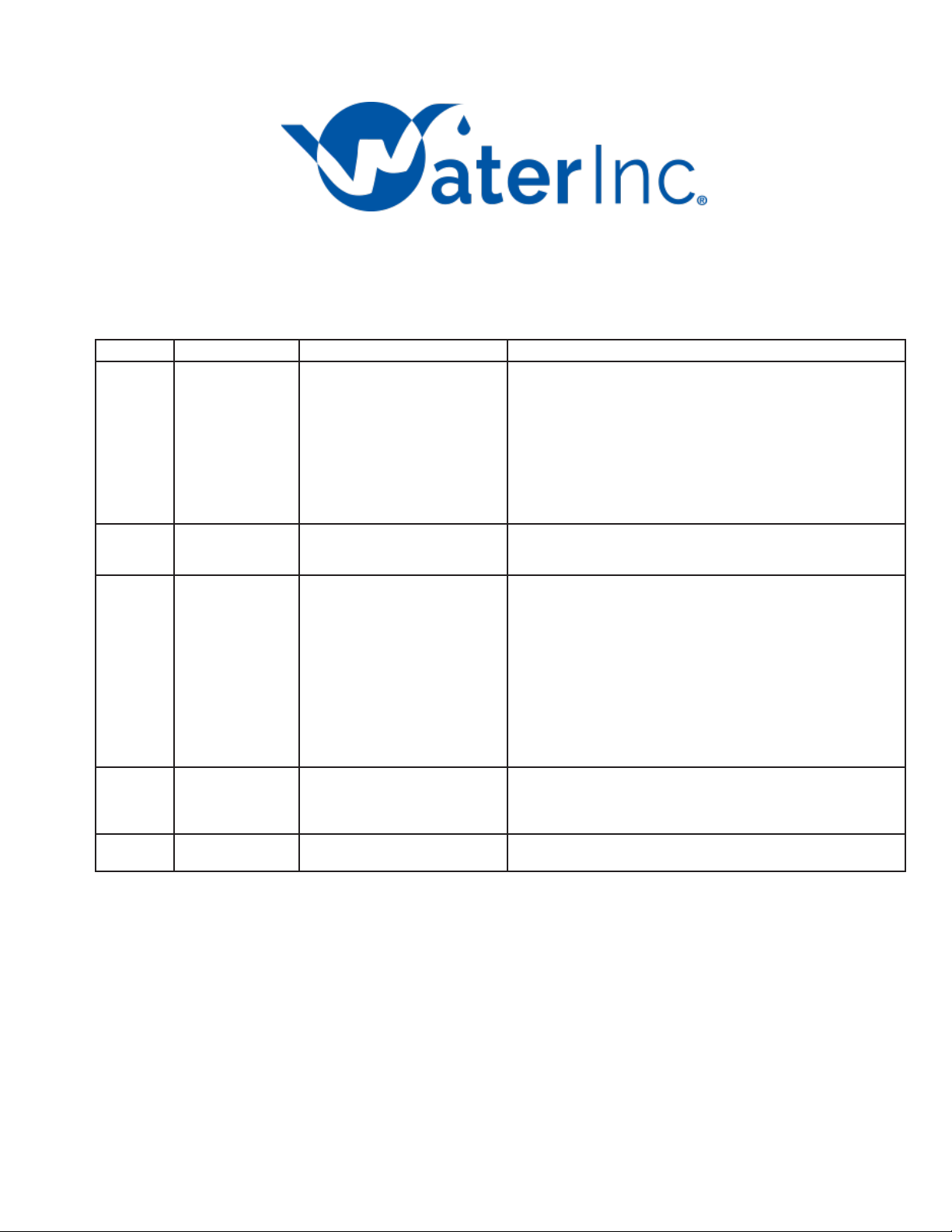
Error Code Error Type Cause
Reset
and
Recovery
---0
Motor Stall /Cam
Sense Error
No state changes in the optical
sensor are detected for six
seconds.
Unplug the unit and plug back in. Allow the control to attempt to find
position again.
Verify the optical sensor is in place with the wires connected to the
circuit board. Verify the motor and drive train components are in good
condition and assembled properly. Check the valve and verify that the
piston travels freely. Replace/reassemble the various components as
necessary.
Plug the unit back in and observe its behavior. If the error reoccurs,
unplug the unit, put it into bypass and contact technical support.
---1
Motor Run-On Error
/Cycle
Sense
Error
An undesired optical sensor state
change occurred.
Non-critical error. Extra optical sensor pulse detected. Press any
button to clear the error. Press extra cycle button to advance motor to
clear error.
---2
Regen
Failure The system has not regenerated
for more than 99 days (or 7 days if
the Control Type has been set to
Day-of-Week).
Perform a Manual Regeneration to reset the error code.
If the system is metered, verify that it is measuring flow by running
service water and watching for the flow indicator on the display. If the
unit does not measure flow, verify that the meter cable is connected
properly and that the meter is functioning properly.
Enter Master Programming Mode and verify that the unit is configured
properly, For the valve configuration. Check that the correct system
capacity has been selected, that the day override is set properly, and
that meter is identified correctly. If the unit is configured as a Day-of-
Week system, verify that at least one day is set ON. Correct the setting
as necessary.
---3
Memory
Error
Control board memory failure.
Perform a Master Reset and reconfigure the system via Master
Programming Mode. After reconfiguring the system, step the valve
through a manual regeneration. If error continues, call technical
support.
---4
Fail
Safe
Error
Valve has failed to find position in
one minute.
Unplug the unit and plug it back in. If error continues, call technical
support.
Thank You for Your Purchase!
Questions ? Please contact Water, Inc. Service Department 1-800-322-9283
F:HousePure/ HP02 5800 Installation 11-02-2022
Table of contents
Other Water Water Filtration System manuals
Popular Water Filtration System manuals by other brands

Tetra
Tetra EX 600 Plus operating instructions

AquaCare
AquaCare Excel 90 instruction manual

Atlas UV
Atlas UV LE Series owner's manual

Honeywell
Honeywell Braukmann kaltecCool PW52-A installation instructions

Hoshizaki
Hoshizaki WOX-40WA-EW installation manual

Austin Springs
Austin Springs AS-RO-75 owner's manual