Watermark SS-TH50 User manual

INSTALLTION FOR
MINIATURE THERMOSTATIC VALVE
Page | 1
SS-TH50 - 1/2” MINIATURE THERMOSTATIC VALVE
Features:
•Ability to pre-select water temperature – thus conserving water
•Compensates for water pressure fluctuations preventing scalding
•Safety button at 100°F prevents accidental scalding
•High flow rates allow for multiple shower applications
•Listed by NSF
Specifications:
oOperating pressure is 20 PSI to 85 PSI
oWhen pressure is higher than 85 PSI a pressure reducer (fitted before the valve) is required.
oTemperature range is 60°F to 115°F
oRecommended supply setting is 45 PSI and 150°F
Note:
•DO NOT USE PLUMBER’S PUTTY ON ANY OF THE BRASS COMPONENTS
This will cause the finish to tarnish and void the warranty. A non-corrosive Alkoxy Silicone is
recommended.
•DURING SWEATING OF LINES DO NOT OVERHEAT CASTING
Overheating may cause damage to internal mechanism and void the manufacturer’s warranty as
well as increase the risk of scalding.
•COPPER ADAPTORS MAY BE REQUIRED TO COMPLETE YOUR INSTALLATION
•Shipping weight (lbs.): 4
•Shipping dimension (in.): 6 x 5 x 4.5
Note:
•Separate wall stops/shut off valves/volume controls (SS-TS150 or SS-TS200) may be needed in
conjunction with this valve. A thermostatic valve’s only function is to mix temperature.
Diagram 1: Flow Rate Vs. Pressure
Rev. 4/18
0
1
2
3
4
5
6
7
8
9
015 30 45 60 70 85
Flow Rate (GPM)
Pressure (PSI)

INSTALLTION FOR
MINIATURE THERMOSTATIC VALVE
Page | 2
Valve Installation
1. Flush the lines of all dirt and debris. Failure to completely flush the lines will cause valve failure and
will void the manufacturer’s warranty.
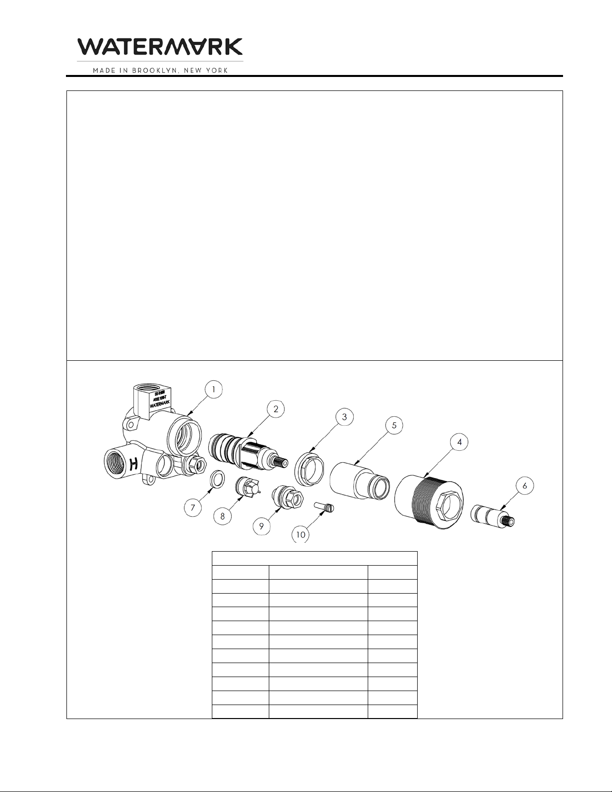
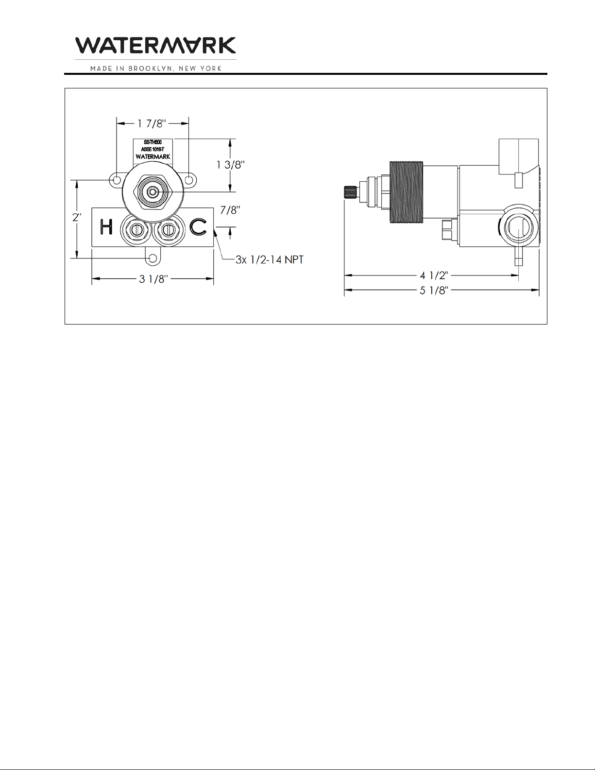
2. Fit the valve on the wall without removing the plastic cover on the control spindle. Turning the
control spindle will change the temperature setting which is pre-calibrated at the factory.
3. Connect the hot water supply to the left inlet of the valve (hot marked with “H”) and cold supply to
the right inlet (cold marked with “C”).
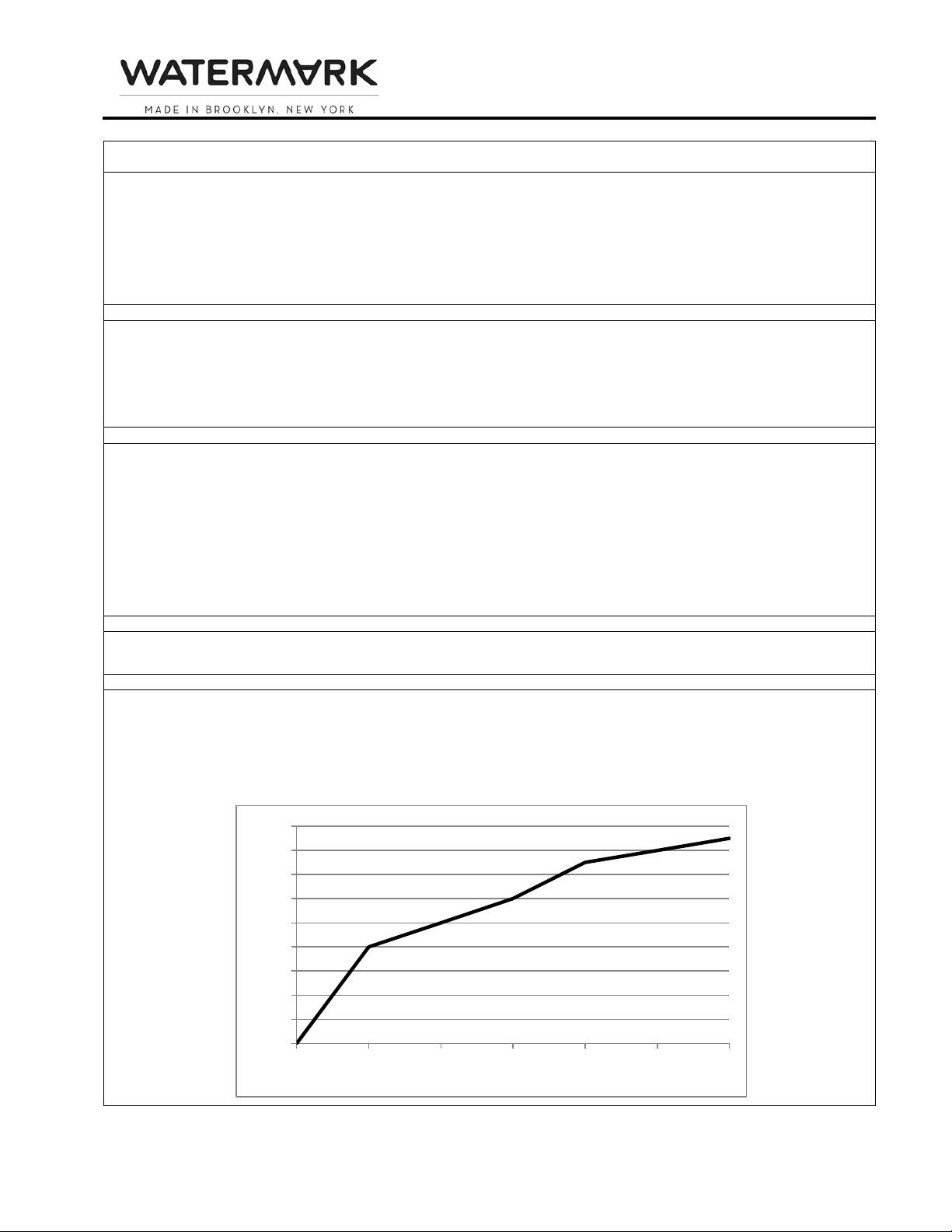
4. Use the Plastic Mudguard (1) (part of the package) to position the Valve (2) in the wall. This is done
by checking the markings on the mudguard for the minimum/ maximum settings which is 2 3/8” to 2
7/8” from the center of the valve inlets to the finished wall.
Diagram 2: Plastic Mudguard
5. Connect the outlet pipe. Install tile stops/volume controls between the thermostatic valve and each
device to be operated.
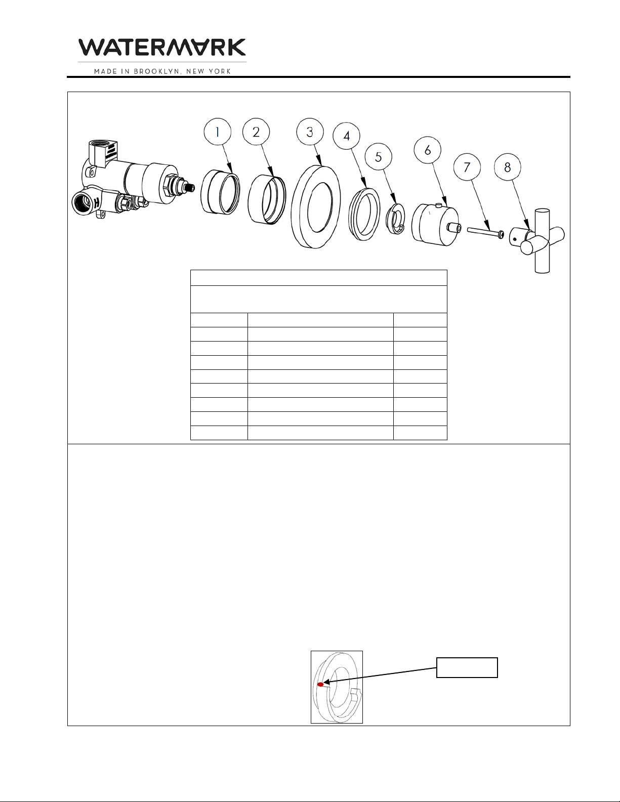
Trim Installation (see Diagram 4)
1. Screw Temperature Control Dome (1)onto valve.
2. Slide the Thermostatic Face Plate (3) onto the valve by sliding over the Temperature Control Dome
(1) and hold in place.
3. Screw Thermostatic Face Plate Lock Ring (4) into Dome Sleeve (2).
4. Lock the Thermostatic Face Plate (3) securely against the wall by screwing Dome Sleeve (2) with
Thermostatic Face Plate Lock Ring (4) onto Temperature Control Dome (1).
5. Ensure Temperature Limit Stop Ring (5) is installed with red dot at 12 o’clock position
6. Install Temperature Control Post (6) onto valve with push button at 12 o’clock position and install
Temperature Control Handle (8) onto Temperature Control Post (6).
Note: Some heavier lever handles come with friction washers to prevent rotation due to gravity. The
thicker of these washers is for use with this valve when needed (see Diagram 3).
Diagram 3

INSTALLTION FOR
MINIATURE THERMOSTATIC VALVE
Page | 3
Diagram 4: Representative Trim
Parts Checklist
Carefully remove all parts from the box. The following
parts should be included.
Item #
Description
Qty.
1
Temperature Control Dome
1
2
Dome Sleeve (raw brass)
1
3
Face Plate
1
4
Lock Ring
1
5
Temperature Limit Stop Ring
1
6
Temperature Control Post
1
7
Temperature Control Screw
1
8
Temperature Control Handle
1
Temperature Setting
The delivered temperature of the valve varies depending on the temperature of the supplied hot water. The
valve is factory set at a supplied temperature of 149°F under balanced pressures. Depending on your
preferred hot water temperature setting, it may be necessary to adjust the calibrations of the valve. The
limit override button is preset at 100°F and can be adjusted as described below.
1. Select 100°F on the control handle.
2. Without turning the handle, remove the handle by unscrewing the screw and pulling off (screw may
be concealed and/or fastened with set screws).
3. Use a thermometer to check the delivered temperature on one of the outlets.
4. Adjust water temperature to 100°F by hand turning the cartridge stem slowly left or right.
5. Ensure that the temperature limit stop-ring in installed with red dot at 12 o’clock position.
6. Push the handle back on the valve with the push button at the 12 o’clock position and fasten in
place.
Diagram 5: Temperature Limit Stop Ring
RED DOT

INSTALLTION FOR
MINIATURE THERMOSTATIC VALVE
Page | 4
Removal and Maintenance of Cartridge (see Diagram 6)
This thermostatic cartridge
has screens to prevent dirt and unwanted particles from damaging the valve.
Clogged screens can cause reduced flow and inefficient temperature mixture by the valve. You can easily
clean the screens by following the instructions below.
1. Remove the trim by following the Trim Installation steps above in reverse.
2. Shut off the water inlets by tightening the two screws at the two check stop valves.
3. Pull off Stem Adapter (6) and Tooth Adapter (5) from valve and unscrew Thread Adapter (4) from
valve with a 23mm socket wrench or other adjustable wrench in a counterclockwise direction.
4. Unscrew Cartridge Nut (3) with a 23mm socket wrench or other adjustable wrench in a counter-
clockwise direction and gently pull out Cartridge (2).
5. Clean the screens and rinse with water. If necessary, soak in a 50/50 mix of white vinegar/ water or
a de-scaling agent until all dirt is dissolved. Grease the o-rings with a silicone based grease and wipe
the housing with a wet cloth before reassembling.
6. Reassemble the valve by reversing these instructions. Make sure the red dot on the temperature
limit stop ring and push button on the handle are both aligned in the 12 o’clock position.
Temperature may need to be reset as per instructions above.
Note: To prevent the handle from accumulating mineral build up which can cause the handle to “lock
up,” the handle must be turned on an occasional basis.
Diagram 6: Cartridge Removal/Check Valve Removal
Parts List
Item #
Description
Qty.
1
Valve Body
1
2
Cartridge
1
3
Cartridge Nut
1
4
Thread Adapter
1
5
Tooth Adapter
1
6
Stem Adapter
1
7
Debris Screen
2
8
Check Valve
2
9
Service Stop Nut
2
10
Service Stop Screw
2

INSTALLTION FOR
MINIATURE THERMOSTATIC VALVE
Page | 5
Troubleshooting
Malfunction
Cause
Remedy
Cannot regulate temperature
Dirt in check valves
Water supply reversed
Valve installed upside down
Remove and clean check valves
Reverse hot and cold supply lines
Reverse valve
Hot and cold water do not mix
Lack of water pressure at one
of the inlets
Blocked shower head
Correct water pressure at source
Remove shower head and clean debris.
If necessary, soak in a 50/50 mix of
white vinegar/ water or a de-scaling
agent until all dirt is dissolved.
Water not hot enough /
Water too hot
Debris in check valves
Valve not properly calibrated
Water heater setting incorrect
Remove and clean check valves
Calibrate valve following instructions on
page 4
Adjust water heater temperature setting
Temperature selected on
handle is different than actual
water temperature
Debris in check valves
Valve not properly calibrated
Uneven hot & cold water
pressure
Remove and clean check valves
Calibrate valve following instructions on
previous page
Check and adjust water pressure for
both hot & cold supply lines
Handle does not turn
Mineral build up
Remove and clean cartridge following
instructions above
Low water pressure
Low water pressure
Debris in cartridge
Debris in check valves
Blocked shower head
Check and adjust water pressure at
source
Remove and clean cartridge following
instructions above
Remove and clean check valves
Remove shower head and clean debris.
If necessary, soak in a 50/50 mix of
white vinegar/ water or a de-scaling
agent until all dirt is dissolved.
Leaking shower head
Fault cartridge in wall stop/
volume control
Repair or replace cartridge in wall stop/
volume control
Valve body too deep into wall
The measured rough in or
finished wall surface is incorrect
Install the proper extension kit:
SS-EXT41

INSTALLTION FOR
MINIATURE THERMOSTATIC VALVE
Miniature Thermostatic Valve Page | 6
Diagram 7
Table of contents
Other Watermark Control Unit manuals
Popular Control Unit manuals by other brands

Wolf
Wolf BML-EXCELLENT Installation, operation and maintenance instructions

Mitsubishi Electric
Mitsubishi Electric MELSEC-QS Series user manual

Eddy Wireless
Eddy Wireless CC2530 instructions

Enclustra
Enclustra Mercury+ SA2 user manual

air avionics
air avionics AIR Control Display 57 Pilot's manual

FireClass
FireClass FC430SAM quick start guide