Waterway 640-18 V Series User manual

810-1800.0522
©2022 Waterway Plastics
MAIN DRAIN OWNER’S MANUAL
WARNING - SUCTION ENTRAPMENT HAZARD
Suction in suction outlets and/or suction outlet
covers which are damaged, broken, cracked,
missing, or unsecured can cause severe injury and/
or death due to the following entrapment hazards:
Hair Entrapment: Hair can become entangled in suction outlet cover.
Limb Entrapment: A limb inserted into an opening of a suction outlet
sump or suction outlet cover that is damaged, broken, cracked, missing,
or not securely attached can result in a mechanical bind or swelling of
the limb.
Body Suction Entrapment: A negative pressure applied to a large
portion of the body or limbs can result in an entrapment.
Evisceration / Disembowelment Entrapment: A negative pressure
applied directly to the intestines through an unprotected suction
outlet sump or suction outlet cover which is damaged, broken, cracked,
missing, or unsecured can result in evisceration / disembowelment
entrapment.
Mechanical Entrapment: There is potential for jewelry, swimsuit,
hair decorations, nger, toe, or knuckle to be caught in an opening of a
suction outlet cover resulting in mechanical entrapment.
USE ONLY GENUINE WATERWAY REPLACEMENT PARTS.
IMPORTANT SAFETY INSTRUCTIONS
Model Number: 640-18xx V 8” Tru Flo
2200 East Sturgis Road, Oxnard CA 93030 • Phone 805.981.0262 • Fax 805.981.9403
Designed,
Engineered &
Manufactured
in the USA.
Read and follow all instructions in this owner’s manual and on the equipment. Failure to follow instructions can cause
severe injury and/or death.
WARNING:
VGBA
2017
IMPORTANT SAFETY INSTRUCTIONS. READ, UNDERSTAND, AND FOLLOW ALL WARNINGS
AND INSTRUCTIONS. SAVE THESE INSTRUCTIONS.
SOFA INSTRUCTIONS
When installing and using this equipment, basic safety precautions shall always be followed, including the following: IMPORTANT
SAFETY INSTRUCTIONS. READ, FOLLOW, AND UNDERSTAND ALL INSTRUCTIONS AND WARNINGS.
Any modication that increases the ow rate of the circulation system shall require re-evaluation of the cover/grate and sump to
ensure that the ow rating of the Suction Outlet Fitting Assembly (SOFA) is not exceeded.
Missing, broken, or cracked cover/grates, sumps, mud-frames, or any other SOFA component shall be replaced before bathers are
allowed to use the pool.
Loose cover/grates shall be reattached before bathers are allowed to use the pool.
SAVE THESE INSTRUCTIONS.

810-1800.0522
©2022 Waterway Plastics
• Suction cover life is 7 years, the sump wall tting life is 15 years, the rest of the components have 25 year life, cover and all
SOFA components shall be replaced on or before the end of service life.
•The use of adhesives or other attachment methods that prevent access to suction piping or SOFA components is prohibited.
•Please refer to Head Loss Curve, suction head measured at the wall tting.
•This is a blockable SOFA as marked on the suction cover.
•Hand tighten screws, DO NOT USE POWER TOOLS TO INSTALL FASTENERS. Ensure proper thread engagement to
prevent cross-threading.
•Ensure proper atness of installation surface.
• When mud-rings, sump and other components are held in place by the interior surface of the pool, the surface should be free
of deterioration or voids
•Damaged Fasteners shall be replaced with original parts, and must be grade 316 stainless steel. The wall tting shall be
inspected for the presence of any CRACK or material loss. Cracked/damaged mud rings, sumps, or wall ttings shall
be replaced.
•No unauthorized eld modications.
•This product is intended for use on gunite, vinyl, berglass, and roto-molded pools, spas and hot tubs.
•No modication shall be made to SOFA structure or ow path unless the conguration has been certied as a new SOFA.
•Service life begins the month and year in which SOFA components are installed with or without water.
•For winterization remove the cover and plug the inlet.
•Use TORX wrench and screw driver for service and removal of fasteners.
•Observe cover/grate/fasteners for damage each operational day.
•During installation ensure components and fastener receptacles are clean, free of debris and obstructions.
•Hand-check cover/grate for snugness to the sump/frame/wall tting after installation.
•SOFA installation components with crack, chunks, or pieces broken o, stripped screw holes, and/or unusual discoloration
should be replaced.
•The mounting surface or interior surface of the pool should be free of deterioration.
•Start installation of screws by hand to ensure proper thread engagement and to prevent cross-threading.
•Do not exceed the safe ow rating of SOFAs as listed.
•All SOFAs should be installed in accordance with Waterway installation instructions.
•No modication shall be made to SOFA structure or ow path unless new conguration has been certied as a new SOFA.
•Under no condition should SOFA special ow rating be exceeded while the pool is open.
•The capacity of secondary circulation system (skimmer, cutters, etc) should not be included when evaluating an individual
suction system ow rating.
•For the ow rating for pools with multiple blockable SOFAs in one body of water without isolation valves: combine all SOFAs,
minus the ow rate of one, if all are not equal use the larger ow rate.
•“Blockable” SOFAs in new pools shall be installed in multiple-SOFA system ONLY.
•“Blockable” SOFAs in existing pools with single SOFA systems shall be installed with an additional anti-entrapment device
or system.
•This SOFA is suitable for in-place replacement.

810-1800.0522
©2022 Waterway Plastics
Failure to remove pressure test plugs and/or plugs used in winterization of the pool/spa from the suction
outlets can result in an increased potential for suction entrapment as described on the previous page.
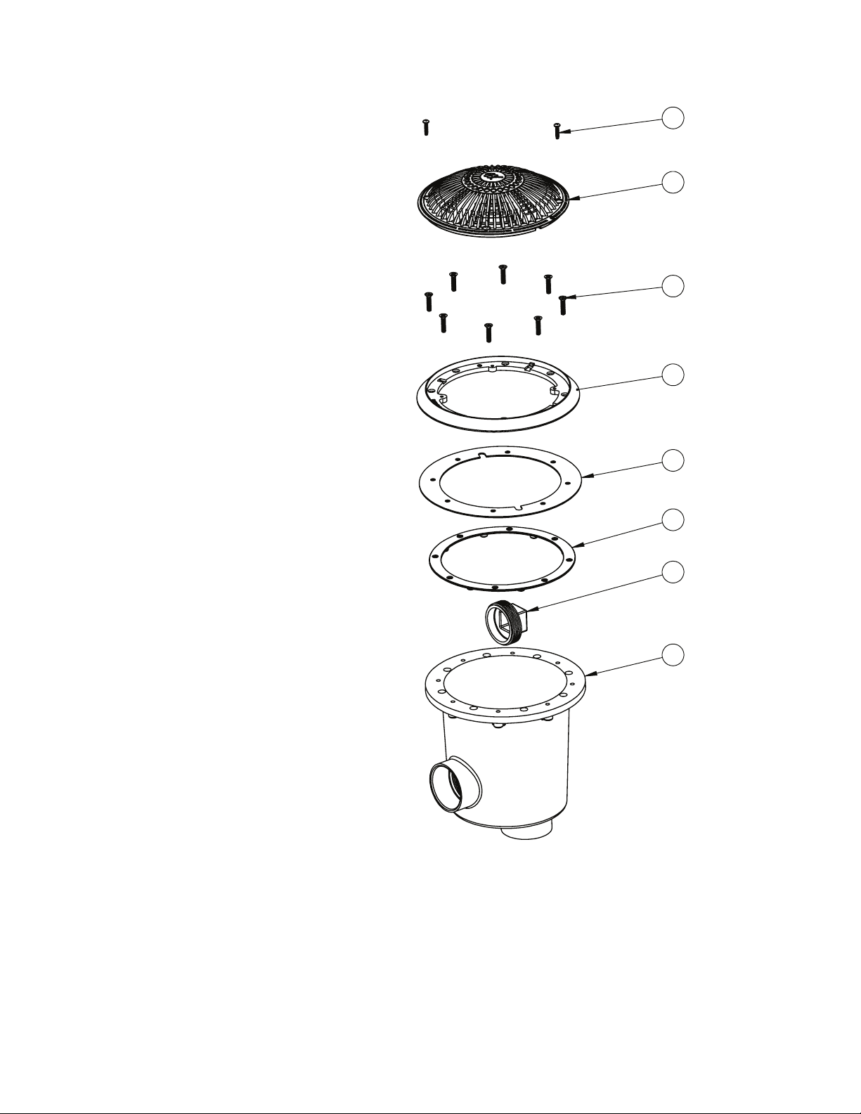
The 8”/ 640-1800 V tting is rated at 120 GPM for oor and 80 GPM for wall. If the tting is missing or broken,
replace with a tting of equivalent rating or higher. Use of a lower rated suction tting could result in
entrapment of the body which could result in serious injury including drowning.
Do not use or operate pool, spa, or hot tub if this suction tting is missing, broken or not secured per
instructions. The suction tting is intended to prevent entrapment of the body. Use of the spa hot tub with a
missing, broken or improperly secured suction grate may result in serious personal injury including drowning.
When the pool, spa or hot tub is in operation, suction is created at this tting. Users of the spa or hot tub must
be instructed not to come in contact with this tting in such a way as to block its orice. If a user of the spa or
hot tub blocks this tting with his/her body, serious personal injury or drowning may occur.
Failure to keep suction outlet components clear of debris, such as leaves, dirt, hair, paper and other material,
can result in an increased potential for suction entrapment as described on the previous page.
Suction outlet components have a nite life. The cover/grate should be inspected frequently and replaced at
least every seven years, or if found to be damaged, broken, cracked, missing, or not securely attached.
WARNING
Do not exceed the safe ow rate. Do not increase ow through system by increasing pump size or horsepower.
Do not allow children to sit, play or interact with main drains or suction outlet.
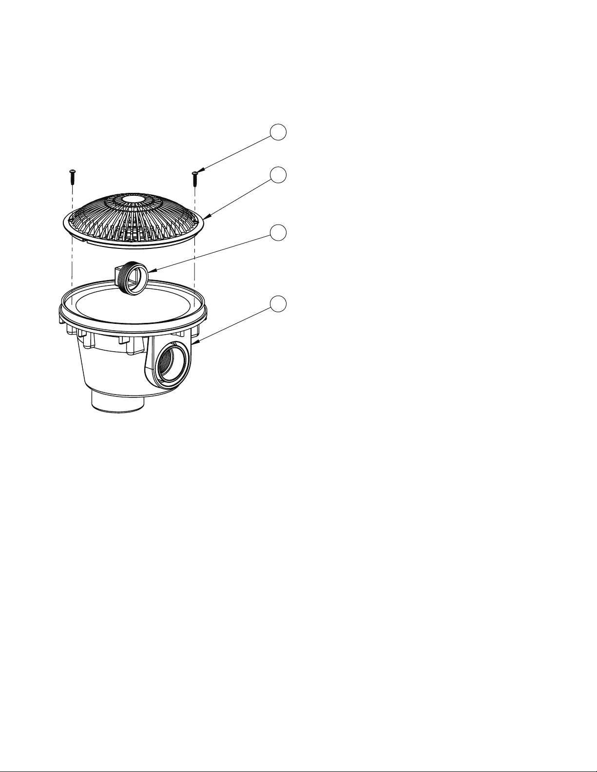
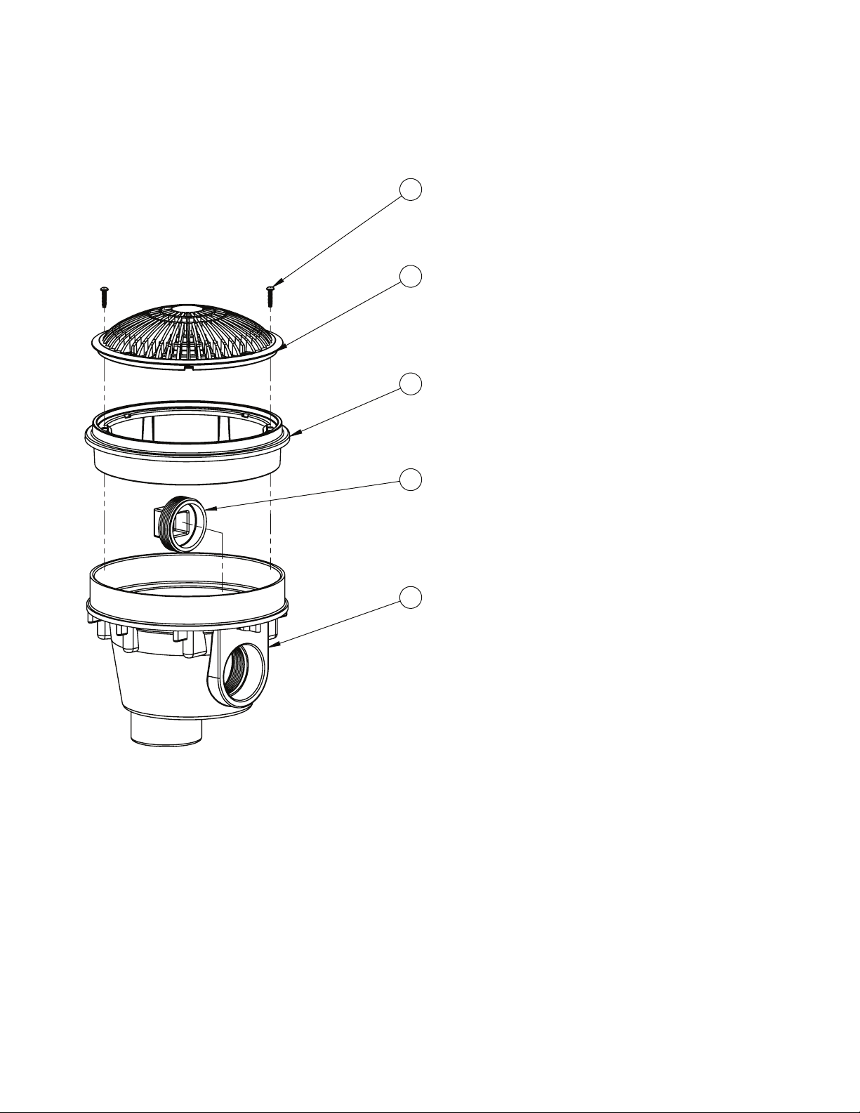
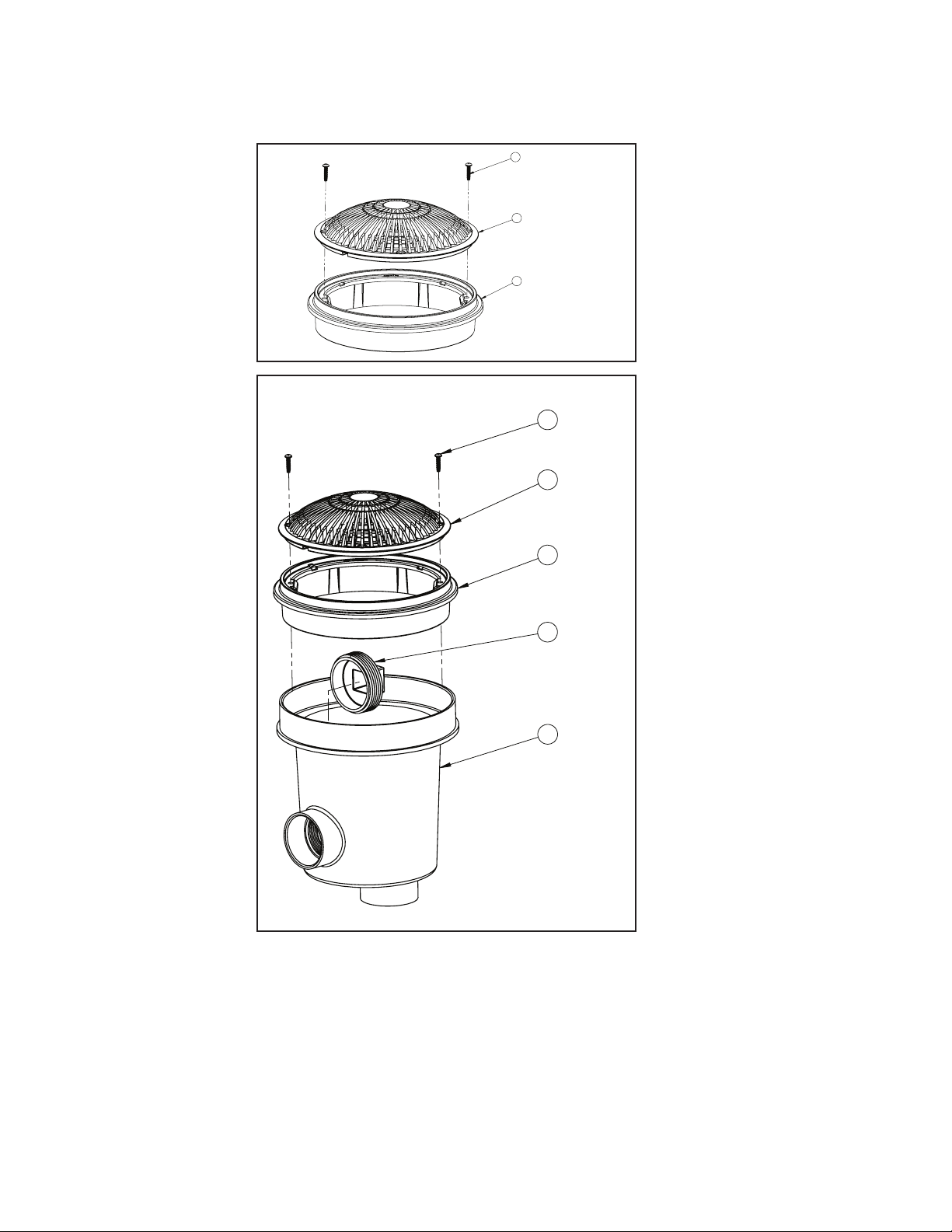
In order to remove the suction cover (for service or winterization), using a Phillips-head screw driver remove
the screws. Inspect both the suction cover and suction tting for any cracks or damages.
Any and all broken or missing parts must be replaced prior to starting spa or pool pump. Never operate spa or
pool without drain cover in place and properly axed, death or serious injury can result.
It is imperative to securely attach the suction cover to the wall ttings (use only the original supplied screws
or obtain original replacements). Do not over tighten the screws. Inspection of fasteners and observation for
damaged/tampered with suction ttings is required.
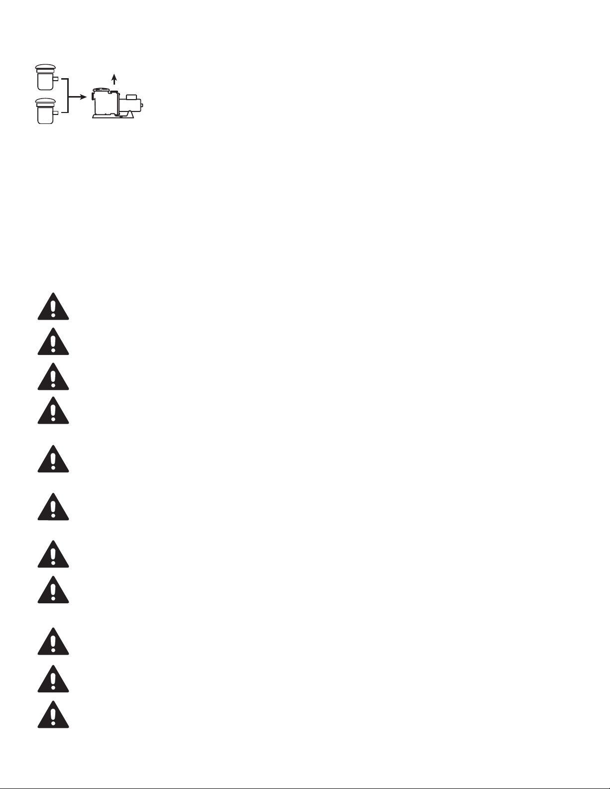
• A minimum of two functioning suction
outlets per pump must be installed.
Suction outlets in the same plane
(i.e. oor or wall) must be installed a
minimum of three feet (3') / 1 meter
apart, as measured from suction pipe center to suction pipe center.
• Dual suction ttings shall be placed in such locations and distances
to avoid “dual blockage”by a user.
• Dual suction ttings shall not be located on seating areas or on the
backrest for such seating areas.
• The maximum system ow rate shall not exceed the ow rating of
any listed (per ANSI/APSP/ICC-16-2017)
suction outlet cover installed. In the event of one suction outlet being
completely blocked, the remaining suction outlets serving the
system shall have a ow rating capable of the full ow of the
pump(s).
• Never use a pool or spa if any suction outlet component is damaged,
broken, cracked, missing, or not securely attached.
• Replace damaged, broken, cracked, missing, or not securely attached
suction outlet components immediately.
• Two or more suction outlets per pump should be installed in
accordance with latest APSP Standards and CPSC guidelines, and
follow all National, State, and Local codes applicable.
• Replace the suction within 7 years from the installation date.
• Installation of a vacuum release system, which relieves entrapping
suction, is recommended.
TO REDUCE THE RISK OF ENTRAPMENT HAZARDS:

810-1800.0522
©2022 Waterway Plastics
3
2
1
819-00801
642-240X V
SG642-2140
ITEM
NO.
QTY.
PART NUMBER
Description
VENDOR
Material
3 2
819-00801
#8 X ¾”, Phillips, Pan Head , Tapping Screw Type,
Blunt Tip, Tri-Lobe, For use in Plastics
N/A
316 SS
2 1
642-2400 V
1 1
642-2140
GRATED ANTI-VORTEX FRAME
WATERWAY
PLASTICS
ASA
SG640-1800 V
3
2
1
819-00801
642-240X V
642-2140
ITEM
NO.
QTY.
PART NUMBER
Description
VENDOR
Material
3 2
819-00801
#8 X ¾”, Phillips, Pan Head , Tapping Screw Type,
Blunt Tip, Tri-Lobe, For use in Plastics
N/A
316 SS
2 1
642-2400 V
1 1
642-2140
GRATED ANTI-VORTEX FRAME
WATERWAY
PLASTICS
ASA
640-1800 V

810-1800.0522
©2022 Waterway Plastics
INSTRUCTIONS FOR CONCRETE MAIN DRAINS SUMP (DUAL PORT)
3
4
1
2
819-00801
642-2400 V
715-1230
672-2410
ITEM
NO.
QTY.
PART NUMBER
Description
VENDOR
Material
4 2
819-00801
#8 X ¾”, Phillips, Pan Head , Tapping Screw Type,
Blunt Tip, Tri-Lobe, For use in Plastics
N/A
316 SS
3 1
642-2400 V
2 1
715-1230
1-1/2" NPT PLUG
1 1
672-2410
GRATED ANTI-VORTEX CONCRETE ASSEMBLY
1. Align cover holes with brass inserts.
2. Hand-tighten supplied screws. DO NOT USE POWER TOOLS.
3. A minimum 2" connecting pipe should be used.

810-1800.0522
©2022 Waterway Plastics
INSTRUCTIONS FOR CONCRETE MAIN DRAINS WITH ADJUSTABLE
COLLAR SUMP (DUAL PORT)
5
4
3
1
2
819-00801
642-240X V
642-2240
715-9910
672-2550
ITEM
NO.
QTY.
PART NUMBER
Description
VENDOR
Material
8 1
WTRSTOP FLG
ROUND_2550
ONLY FILL IN FOR
PURCHASE ITEM
ABS
7 1
MIDDLE CROSS
SECTION
PLASTER2_2550
ONLY FILL IN FOR
PURCHASE ITEM
ABS
6 1
MIDDLE CROSS
SECTION
PLASTER_2550
ONLY FILL IN FOR
PURCHASE ITEM
ABS
5 2
819-00801
#8 X ¾”, Phillips, Pan Head , Tapping Screw Type,
Blunt Tip, Tri-Lobe, For use in Plastics
N/A
316 SS
4 1
642-2400 V
3 1
642-2240
EXTENDED MAIN DRAIN FRAME
ONLY FILL IN FOR
PURCHASE ITEM
ASA
2 1
715-9910
PLUG, PIPE, 2"
PVC
1 1
672-2550
GRATED ANTI-VORTEX CONCRETE ASSEMBLY
1. Align cover holes with brass inserts.
2. Hand-tighten supplied screws. DO NOT USE POWER TOOLS.
3. A minimum 2" connecting pipe should be used.

810-1800.0522
©2022 Waterway Plastics
INSTRUCTIONS FOR VINYL LINER MAIN DRAINS (DUAL PORT)
4
8
7
6
5
3
2
1
672-2520
715-9910
711-2600
806-3000
642-209X
819-6940
642-240X V
819-00801
ITEM
NO.
QTY.
PART NUMBER
Description
VENDOR
Material
1 2
819-00801
#8 X ¾”, Phillips, Pan Head , Tapping Screw Type,
Blunt Tip, Tri-Lobe, For use in Plastics
N/A
316 SS
7 1
715-9910
PLUG, PIPE, 2"
PVC
5 1
806-3000
GASKET FLAT VINYL LINER 8 INCH SUCTION
8
819-6941
SCREW, #12 X 1 PHIL FLAT S/M/S TYPE B, 316-SS
N/A
316 SS
3 1
825-3120
SCREW PKG KIT FOR 10"ULTR SMPS 3"IN SLP ( V/L )
6 1
711-2600
SEAL GASKET VINLY LINER 8 INCH SUCTION
N/A
KRATON
8 1
672-2520
X
PVC
2
820-4175
INSERT, #8-32 SPLIT
WATERWAY
PLASTICS
Copper
1
642-2090
MAIN DRAIN VINYL LINER MOUNT. PLATE (MOLDED) ASA
4 1
642-2090
2 1
642-2400 V
• Grated Anti-Vortex Cover is contoured to keep auto-cleaners from sticking
• Vinyl liner mounting plate is angled for auto-cleaners to climb over
• Body is type 1 PVC: better for glue joints
GRATED ANTI-VORTEX VINYL LINER ASSEMBLY
1. Install rubber gasket to body by pushing in raised alignment cups into slots
in body (see Diagram A).
2. Lay vinyl liner over main drain.
3. Put ber gasket and mounting plate on top of vinyl liner over main drain.
4. Install all eight screws. (If this is your rst time, ask where purchased this
drain exactly how to do it with the pool you brought.)
5. Align cover holes with brass inserts and install screws.

810-1800.0522
©2022 Waterway Plastics
INSTRUCTIONS FOR CONCRETE MAIN DRAINS WITH DEEP SUMP
DUAL PORT
4
3
1
2
819-0081
642-2400 V
715-9930
672-2610
ITEM
NO.
QTY.
PART NUMBER
Description
VENDOR
Material
7 1
WTRSTOP FLG
ROUND_7410
ONLY FILL IN FOR
PURCHASE ITEM
ABS
6 1
MIDDLE X-SECT
POOL_ 7410
ONLY FILL IN FOR
PURCHASE ITEM
ABS
5 1
MIDDLE X-SECT
PLASTER_7410
ONLY FILL IN FOR
PURCHASE ITEM
ABS
4 2
819-00801
#8 X ¾”, Phillips, Pan Head , Tapping Screw Type,
Blunt Tip, Tri-Lobe, For use in Plastics
N/A
316 SS
3 1
642-2400 V
2 1
715-9930
PLUG, 2.5" NPT
PVC
1 1
672-2610
8" MAIN DRAIN SUMP CONCRETE BODY SxB 2.5" S x
2.5" S
GRATED ANTI-VORTEX CONCRETE ASSEMBLY
1. Align cover holes with brass inserts.
2. Hand-tighten supplied screws. DO NOT USE POWER TOOLS.
3. A minimum 2" connecting pipe should be used.

810-1800.0522
©2022 Waterway Plastics
INSTRUCTIONS FOR CONCRETE MAIN DRAINS (DUAL PORT)
WITH EXTENDED COLLAR
CONCRETE ASSEMBLY
1. Align cover holes with brass inserts.
2. Hand-tighten supplied screws. DO NOT USE POWER TOOLS.
3. A minimum 2" connecting pipe should be used.
3
2
1
819-00801
642-2400 V
642-2240
ITEM
NO.
QTY.
PART NUMBER Description
VENDOR
Material
3 2
819-00801
#8 X ¾”, Phillips, Pan Head , Tapping Screw Type,
Blunt Tip, Tri-Lobe, For use in Plastics
N/A
316 SS
2 1
642-2400 V
1 1
642-2240
EXTENDED MAIN DRAIN FRAME
ONLY FILL IN FOR
PURCHASE ITEM
ASA
4
5
3
1
2
819-00801
642-240x V
642-2240
715-9930
672-2650

810-1800.0522
©2022 Waterway Plastics
INSTRUCTIONS FOR CONCRETE
MAIN DRAINS (DUAL PORT)
CONCRETE ASSEMBLY
1. Align cover holes with brass inserts.
2. Hand-tighten supplied screws. DO NOT USE POWER TOOLS.
3. A minimum 2" connecting pipe should be used.
INSTRUCTIONS FOR VINYL LINER
MAIN DRAINS (DUAL PORT)
• Cover is contoured to keep auto-cleaners from sticking
• Vinyl liner mounting plate is angled for auto-cleaners to climb over
• Body is type 1 PVC: better for glue joints
VINYL LINER ASSEMBLY
1. Install rubber gasket to body by pushing in raised alignment cups into slots
in body (see Diagram A).
2. Lay vinyl liner over main drain.
3. Put ber gasket and mounting plate on top of vinyl liner over main drain.
4. Install all eight screws. (If this is your rst time, ask where you purchased
this drain exactly how to do it with the pool you bought.)
5. Align cover holes with brass inserts and install screws.
3
2
1
819-00801
642-2400 V
642-2140
ITEM
NO.
QTY.
PART NUMBER
Description
VENDOR
Material
3 2
819-00801
#8 X ¾”, Phillips, Pan Head , Tapping Screw Type,
Blunt Tip, Tri-Lobe, For use in Plastics
N/A
316 SS
2 1
642-2400 V
1 1
642-2140
GRATED ANTI-VORTEX FRAME
WATERWAY
PLASTICS
ASA
4
3
1
2
819-0081
642-2400 V
715-9930
672-2610
ITEM
NO.
QTY.
PART NUMBER
Description
VENDOR
Material
7 1
WTRSTOP FLG
ROUND_7410
ONLY FILL IN FOR
PURCHASE ITEM
ABS
6 1
MIDDLE X-SECT
POOL_ 7410
ONLY FILL IN FOR
PURCHASE ITEM
ABS
5 1
MIDDLE X-SECT
PLASTER_7410
ONLY FILL IN FOR
PURCHASE ITEM
ABS
4 2
819-00801
#8 X ¾”, Phillips, Pan Head , Tapping Screw Type,
Blunt Tip, Tri-Lobe, For use in Plastics
N/A
316 SS
3 1
642-2400 V
2 1
715-9930
PLUG, 2.5" NPT
PVC
1 1
672-2610
8" MAIN DRAIN SUMP CONCRETE BODY SxB 2.5" S x
2.5" S
1
2
3
4
5
6
825-315x
642-241x V
642-314x
711-3140
715-9950
672-2940

810-1800.0522
©2022 Waterway Plastics
WARRANTY
For product registration visit: www.waterwayplastics.com.
For Warranty questions or claims please contact point of purchase.
-0.5
0
0.5
1
1.5
2
2.5
0 50 100 150 200 250 300 350
Head (In. Hg.)
Flow Rate (GPM)
8" TRU-FLOW Head Loss Curve

810-1800.0522
©2022 Waterway Plastics
AA
5"
MIN
1.5"
MIN
6.5"
SECTION A-A
PLASTER
642-240X V
2" PIPE
2" PIPE
POOL STRUCTURE
5.25" FLOW PATH
4" FLOW PATH
FINISH SURFACE
OF THE POOL
FIELD FABRICATED SUMP
AA
SECTION A-A
2" SOC
2" SOC
642-240X V
5.25" FLOW PATH
4" FLOW PATH
FINISH SURFACE
OF THE POOL
FLOW PATH
AA
SECTION A-A
2.5" SOC
2.5" SOC
642-2400 V
8" FLOW PATH
4" FLOW PATH
FLOW PATH
FINISH SURFACE
OF THE POOL
AA
3.5"
MIN
7.5"
MIN
SECTION A-A
2.5" PIPE
2.5" PIPE
642-2400 V
PLASTER
OF THE POOL
FINISH SURFACE
FIELD BUILT SUMP WITH 2.5" PIPE
POOL STRUCTURE
4" FLOW PATH
8" FLOW PATH
Other Waterway Lighting Equipment manuals
Popular Lighting Equipment manuals by other brands

Future light
Future light DJ-SCAN 600 user manual

Intex
Intex 164122ND owner's manual

walser
walser GLAM Series instruction manual

Lightolier
Lightolier Calculite ProSpec PA2P3075 specification

Cooper Lighting
Cooper Lighting SURE-LITES SLX Series installation instructions

X-laser
X-laser X-Pod User information