Watlow QPAC-01 User manual

Made in the U.S.A.
$10.00
QPAC
User’s Manual
Modular SCR
Power Control
0600-0027-0001 Rev C
July 2003
1241 Bundy Blvd., P.O. Box 5580, Winona, MN 55987-5580,
Tel: +1 (507) 454-5300, Fax: +1 (507) 452-4507 http://www.watow.com

Starting Out
2How to Use the Manual
QPAC User's Manual
This manual will make your job easier.
Reading it and applying the information is a
good way to become familiar with the QPAC. An overview:
Introduction, Chapter 1, Page 4.
Installation and Wiring, Chapter 2, Page 6.
Operation, Chapter 3, Page 25.
Troubleshooting, Page 28
Specifications
Warranty
Notes
A bold text "NOTE" marks a short message in the margin to alert you to an important
detail.
Safety Information
This user's manual also has boldface safety information notes to protect both you and
your equipment. Please be attentive to them. Here are explanations:
ç
The CAUTION symbol (exclamation point) in the wide text column alerts you to a
"CAUTION," a safety or functional hazard which could affect your
equipment
or its
performance. A full explanation is in the narrow column on the outside of the page.
∑
The WARNING symbol (lightning bolt) in the wide text column alerts you to a "WARN-
ING," a safety hazard which could affect you and the equipment. A full explanation is in
the narrow column on the outside of the page.
Your Feedback
We welcome comments or suggestions on this manual, please contact:
Technical Writer, Watlow Winona, 1241 Bundy Blvd, P.O. Box 5580, Winona, MN
55987-5580. Phone: 507-454-5300; Fax: 507-452-4507. The QPAC User's Manual is
copyrighted by Watlow Winona, Inc. © July 2003 with all rights reserved. (2392)
Technical Assistance
If you encounter a problem with your Watlow controller, review your configuration
information to verify that your selections are consistent with your application: inputs,
outputs, alarms, limits, etc. If the problem persists, you can get technical assistance
from your local Watlow representative (see back cover), by e-mailing your questions to
p.m., Central Standard Time (CST). Ask for for an Applications Engineer. Please have
the following information available when calling:
• Complete model number • All configuration information
• User’s Manual • Serial Number
The model, part number, and serial numbers can be found on the label on the outside of
the case.
Use The Manual
Starting Out
Install/Wire
Operation
First…
Appendix
How to Use the Manual
ç
CAUTION:
Details of a "Caution"
appear here, in the
narrow box on the
outside of each page.
∑
WARNING:
Details of a "Warning"
appear here, in the
narrow box on the
outside of each page.
NOTE:
Details of a "Note"
appear here, in the
narrow box on the
outside of each page.

Starting Out
3
QPAC User's ManualHow to Use the Manual
Contents
Table of Contents
Page Item
2How to Use the Manual
3How to Read the QPAC Model Number
3Contents
4Starting Out With The QPAC - Chapter 1
4General Description
5Steps To Put Your Power Control To Work
6How To Install And Wire The QPAC - Chapter 2
6System Planning
6Mounting The QPAC
7Case Style A Mounting: QPAC-01, 30-50A
8Case Style B Mounting: QPAC-01, 75-100A; QPAC-32, 30-100A
9, 10 Fuse Templates
11, 12 Case Style C Mounting: QPAC-01, 150-300A; QPAC-32, 150-300A;
QPAC-33, 150-300A
13 Case Style E Mounting: See Addendum for 400 to 1,000 Amp QPAC
13 Case Style F Mounting: QPAC-33, 30-100A
14, 15 Power and Load Wiring, QPAC-01
16, 17 Power and Load Wiring, QPAC-32
17 Power and Load Wiring, QPAC-33
18 Input Signal Wiring
18 CA Control Card
19 CD Control Card dc Input
19 CD Control Card Contact Closure Input
20 AF, AL, BF and BV Control Cards
20 AF, AL, BF and BV Potentiometer Input
20 AF, AL, BF and BV dc Input Connections
21 AF, AL, BF and BV Auto/Manual Input
21 Interlock
21 Soft Start
21, 22 AL Control Card Current Transformer Connections
23 DH Option, Open Heater or Shorted SCR Detector
24 QPAC System Wiring Example
25 How to Operate The QPAC - Chapter 3
25 Setup Adjustments
25 Phase Rotation Adjustments
25, 26 Bias And Gain Adjustments
27 Current Limit Adjustments
Appendix
28 Troubleshooting
29, 30 Specifications
31 Ordering Information
32 Accessories
33 Warranty, Returns
34 Index
The QPAC model number provides phase, supply voltage, amperage, and
control type information, in that order. For example:
Fan Cooled 30Amp (30A @ 480Vac, 3Ø)
480Vac Supply Burst Fired, Variable Time Base
3 Phase 2-Leg Open Heater, Shorted SCR Detector
Q32-481-030-BV2
Refer to the model number breakdown on page 31 for a complete listing.
How to Read the QPAC Model Number

Starting Out
4Getting Started, Chapter 1
QPAC User's Manual
Starting Out
Figure 1 -
The QPAC-01
SCR Power Control
General Description
The QPAC Power Controls are a family of solid state controls used for electric
heating applications. A solid state power control provides output power that is
proportional to the input command signal from a temperature control. This
proportional output power helps to produce a closely controlled heater tem-
perature, which saves energy and prolongs heater life by holding heater
elements at a nearly constant temperature.
The QPAC has a modular construction with plug-in features for flexibility. The
three modules of the QPAC are the Power Base, Transformer, and Control
Chapter 1
Starting Out With The QPAC,
Modular SCR Power Control

Starting Out
5
QPAC User's ManualGetting Started, Chapter 1
Starting Out
Card. See Figure 2. Power Bases are avaliable in 30 to 300A ratings with
UL508 and C-UL listing and 400-1,000 amps non-agency approved in single
phase, three phase-two leg and three phase-three wire configurations. A
Transformer plugged into the Power Base allows the QPAC to operate on any
voltage from 120 to 480Vac fan. 575Vac consult factory. The plug-in Control
Card sets the QPAC’s firing mode. Control Cards are available in solid state
contactor, burst firing (zero cross), or phase angle firing with a wide variety of
options. This modular approach, using a standard Power Base with plug-in
Transformers and Control Cards, allows power control users, distributors and
OEMs to maintain minimum inventories while still providing rapid service.
The different QPACs provide the types of power control needed for different
power sources and loads. The QPAC-01 is designed for all single phase
power sources and loads. The QPAC-32 is for three phase zero cross applica-
tions such as resistance heating elements, balanced or unbalanced. The
QPAC-33 is best suited for balanced three phase, phase angle applications
requiring soft start or current limiting, or with inductive loads.
Steps To Put Your Power Control To Work
To put your QPAC to work, we suggest the following steps:
•Read the User's Manual.
•Plan your installation and wiring.
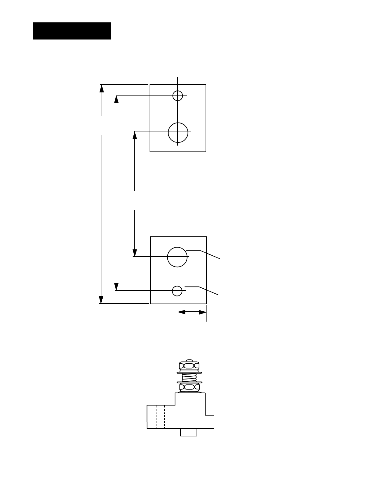
•Mount the QPAC.
•Wire your QPAC to the system.
•Start the system and, if applicable, adjust the bias and gain on the QPAC.
•That's all there is to it!
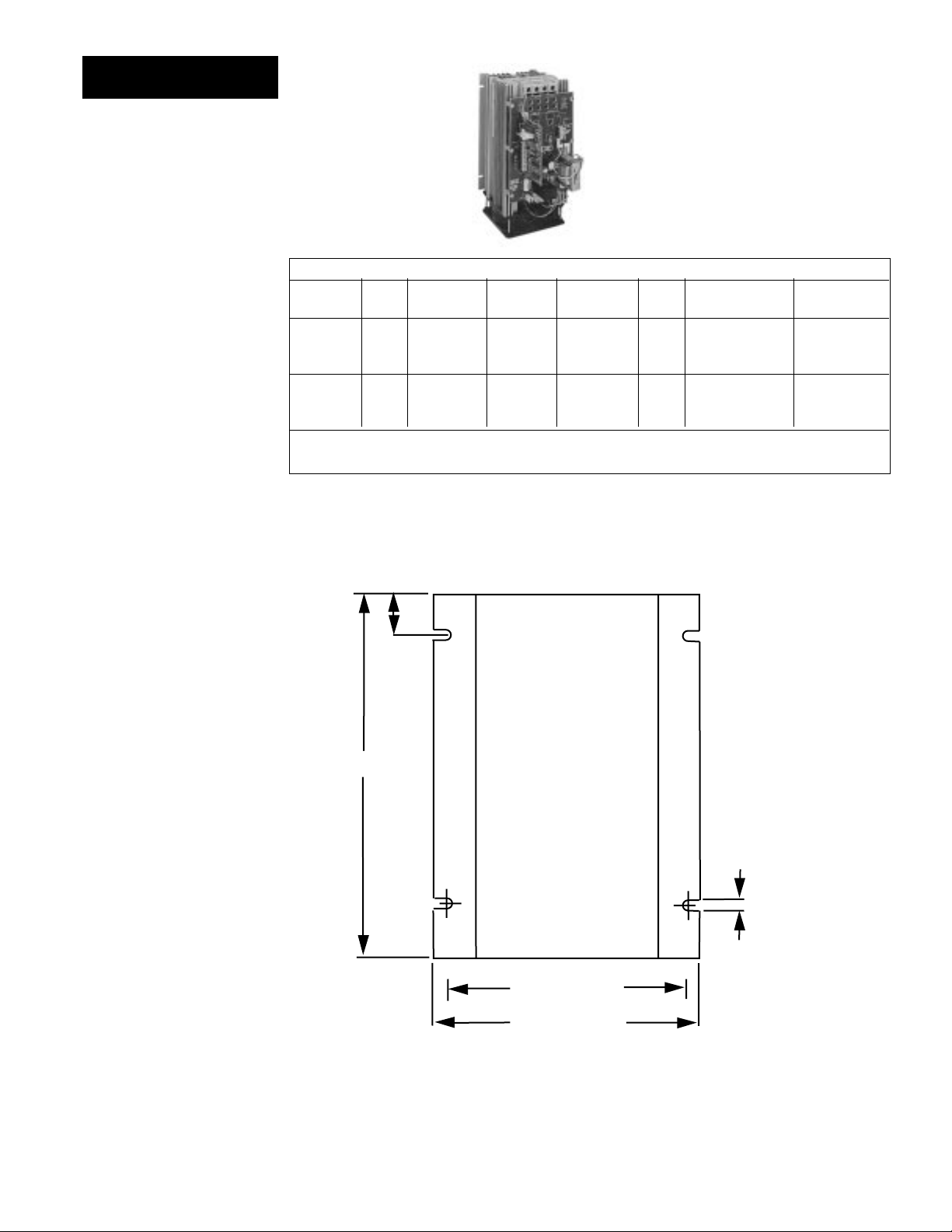
Figure 2 -
QPAC Modularity
Overview
QBF 08-5289
U1
U2
TB1
Control Cards
•Solid state contactor, AC input, CA
•Solid state contactor, DC input, CD
•Burst firing (zero cross) fixed time base, BF
•Burst firing (zero cross) variable time base, BV
•Phase angle control, AF *
•Phase angle control with current limiting, AL *
*Note: For 1Ø and 3Ø, 3 wire controls
only; not for 3Ø, 2 leg controls.
Power Bases With Motherboards
• QPAC-01: 1Ø, 30 - 300A
•QPAC-32: 3Ø, 2 leg, 30 - 300A
•QPAC-33: 3Ø, 3 wire, 30 - 300A
Plug-in transformers (50/60 Hz.)
•120Vac
•208/240Vac
•380Vac
•415Vac
•480Vac
•575Vac, consult factory

Starting Out
6QPAC User's Manual Install and Wire, Chapter 2
Current Semi- Minimum Bending Radius Lugs QPAC Fuse
(Amps) conduc- Recom- Accept Model Mounting
tor Fuse mended inches (mm) # Wire Number
Rating Wire Size
(Amps)
30 2ea, 20 10 N/A 18 to 4 Q01 Onboard
2ea, 40 Q32 External
3ea, 40 Q33 External
50 2ea, 30 8 1.5 (38) 18 to 4 Q01 Onboard
2ea, 70 Q32 External
3ea, 70 Q33 External
75 100 4 2 (51) 8 to 0 All External
100 125 1 3 (76) 8 to 0 All External
150 200 3/0 4 (102) 4 to 3/0 All Onboard
200 250 250 MCM 4.5 (114) 6 to 350 MCM All Onboard
300 400 500 MCM 8 (203) 4 to 500 MCM All Onboard
Installation
Chapter 2
How to Install and Wire the QPAC
System Planning
This chapter tells you how to install the QPAC. All mounting and wiring infor-
mation is right here. Watlow power controls are thoroughly tested before
leaving the factory, so the QPAC is ready to install when you receive it.
This chapter is divided into three sections which describe the three steps you
need to do to install the QPAC—mounting, power wiring and control card
wiring. The first section lists the mounting information for each of the three
types of QPACs, which, depending on amperage, use one of five case styles.
The second section describes the power and load wiring of the QPACs and
semiconductor fuses, if required. The last section describes the input signal
wiring to the QPAC Control Card.
Before you begin working, read through this chapter to gain an understanding
of the entire installation. Consider the installation carefully. Plan the power,
load, and input signal wiring before mounting the QPAC. Also refer to any
noise guidelines in the temperature control documentation before proceeding.
Mounting the QPAC ∫
The physical size and mounting dimensions of the QPACs are different for
different current ratings. Find the "Case Style" photo on the next pages which
match your QPAC. The table and figure accompanying each case style will
give you corresponding physical dimensions and mounting footprint. The table
also indicates if the units are equipped with fans and externally-mounted fuses.
External fuse mounting templates also accompany the case style drawings. All
QPACs must be mounted vertically, power connections on top, for proper
cooling. Use the wiring data table below for wire sizes and bending radii.
Table 1 -
QPAC Wiring Data
Mounting
∑
WARNING:
To avoid potential
electric shock and
other hazards, all
mounting and wiring
for the QPAC must
conform to the Na-
tional Electric Code
(NEC) and other lo-
cally applicable
codes.

Starting Out
7
QPAC User's ManualInstall and Wire, Chapter 2
Case Style A
Table 2 -
QPAC Case Style A
Overall Dimensions
Case Style A Dimensions
Model Amps Height (H) Width Depth Fans Fuses
in (mm) in (mm) in (mm)
QPAC-01 30 7 178 See 6.5 165 None Two, Onboard
QPAC-01 50 9 229 Below 6.5 165 None Two, Onboard
ç
CAUTION:
Mount the QPAC
vertically (height
dimension vertical)
for proper cooling.
Failure to do so
could result in
power control
malfunction.
Figure 4 -
QPAC Case Style A
Mounting Footprint
Figure 3 -
QPAC Case Style A
ç
H less
2.00 (50.8mm)
5.00 (127mm)
5.80 (147mm)
6.60 (168mm)
H
Mounting Clip
Hole 0.19 (5mm)

Starting Out
8QPAC User's Manual Install and Wire, Chapter 2
Figure 6 -
QPAC Case Style B
Mounting Footprint
Figure 5 -
QPAC Case Style B
Table 3 -
QPAC Case Style B
Overall Dimensions
Case Style B
ç
CAUTION:
Mount the QPAC
vertically (height
dimension vertical)
for proper cooling.
Failure to do so
could result in
power control
malfunction.
Case Style B Dimensions
Model Amps Height (H) Width Depth Fans Fuses Holder (max.)
in (mm) in (mm) in (mm) in (mm)
QPAC-32 30 10.5 267 5 127 8.5 208 One Two, External* 5.69 145
QPAC-01 75 10.5 267 5 127 8.5 208 One One, External** 4.90 124
QPAC-01 100 10.5 267 5 127 8.5 208 One One, External** 4.90 124
QPAC-32 50 10.5 267 5 127 8.5 165 One Two, External* 5.69 145
QPAC-32 75 14.5 368 5 127 8.5 229 One Two, External** 4.90 124
QPAC-32 100 14.5 368 5 127 8.5 208 One Two, External** 4.90 124
* Note: See external fuse mounting drawing, Figure 7, Page 9.
**Note: See external fuse mounting drawing, Figure 8, Page 10.
ç
1.00
(25mm)
0.19
(5mm)
4.50 (114mm)
5.07 (129mm)
H

Starting Out
9
QPAC User's ManualInstall and Wire, Chapter 2
3.63
(92mm)
5.07
(129mm)
5.69
(145mm)
0.63
(16mm)
0.44
(11mm
0.22
(6mm)
Drill & tap
hole "B"
for #10
fasteners
A
B
Fuse Template
Figure 7 -
Fuse Holder Kit
Mounting Template
for:
QPAC-32, 30 & 50A
(2 Fuse Kits)
QPAC-33, 30 & 50A
(3 Fuse Kits)
Fuse Holder
(side view)
Use the next two pages as templates for mounting your fuse holder kit. Choose
the size that matches your kit and carefully punch out the template along the
perforation.
ç
CAUTION:
Spacing for multiple
fuses must conform
to the National
Electric Code (NEC)
and any other local
electrical codes.
A
B
Stud Size 5/16"

Starting Out
10 QPAC User's Manual Install and Wire, Chapter 2
0.63
(16mm)
0.44
(11mm
0.22
(6mm)
Drill & tap
hole "B"
for #10
fasteners
A
B
4.28
(109mm)
4.90
(124mm)
2.84
(72mm)
Fuse Template
Figure 8 -
Fuse Holder Kit
Mounting Template
for:
QPAC-01, 75 & 100A
(1 Fuse Kit)
QPAC-32, 75 & 100A
(2 Fuse Kits)
QPAC-33, 75 & 100A
(3 Fuse Kits)
Fuse Holder
(side view)
Use this page as a template for mounting your fuse holder kit. Choose the size
that matches your kit and carefully punch out the template along the perforation.
ç
CAUTION:
Spacing for multiple
fuses must conform
to the National
Electric Code (NEC)
and any other local
electrical codes.
A
B
Stud Size 5/16"

Starting Out
11
QPAC User's ManualInstall and Wire, Chapter 2
Case Style C Dimensions
Model Amps Height Width Depth Fans Fuses
in (mm) in (mm) in (mm)
QPAC-01 150 13 330 6.9 175 10.25 260 One On Heat Sink
QPAC-01 200 13 330 6.9 175 10.25 260 One On Heat Sink
QPAC-01 300 13 330 6.9 175 10.25 260 One On Heat Sink
QPAC-32 150 13 330 14.0 348 10.25 260 Two On Heat Sink
QPAC-32 200 13 330 14.0 348 10.25 260 Two On Heat Sink
QPAC-32 300 13 330 14.0 348 10.25 260 Two On Heat Sink
QPAC-33 150 13 330 21.0 533 10.25 260 Three On Heat Sink
QPAC-33 200 13 330 21.0 533 10.25 260 Three On Heat Sink
QPAC-33 300 13 330 21.0 533 10.25 260 Three On Heat Sink
Note: On 575 V~(ac) applications, the fuses are mounted external to the QPAC.
Case Style C
Figure 9 -
QPAC Case Style C
Table 4 -
QPAC Case Style C
Overall Dimensions
Figure 10 -
QPAC Case Style C,
QPAC-01, 150, 200,
300A Single Phase
Mounting Footprint
ç
CAUTION:
Mount the QPAC
vertically (height
dimension vertical)
for proper cooling.
Failure to do so
could result in
power control
malfunction.
∫
WARNING:
Style C heatsinks
are electrically HOT.
13.00
(330mm)
7.00 (178mm)
0.38 (10mm)
2 PL
FAN
P
U
MOUNT
3.50 (89mm)
11.75
(299mm)
3.63
(92mm)
ç∫

Starting Out
12 QPAC User's Manual Install and Wire, Chapter 2
Case Style C
Figure 11 -
QPAC Case
Style C, Q32,
150, 200, 300A,
Three Phase-2 Leg
Mounting Footprint
Figure 12 -
QPAC Case
Style C, Q33,
150, 200, 300A,
Three Phase-3 Wire
Mounting Footprint
ç
CAUTION:
Mount the QPAC
vertically (height
dimension vertical)
for proper cooling.
Failure to do so
could result in
power control
malfunction.
∫
WARNING:
Style C heatsinks
are electrically HOT.
ç
∫
ç∫
3.63
(92mm)
7.00
(178mm) 0.63 (16mm)
11.75
(299mm)
13.00
(33mm)
21.00 (533mm)
.375 (10mm)
6 PL
P
U
MOUNT
FAN
FAN FAN
7.00
(178mm)
3.50
(89mm)
14.00 (356mm)
4 PL
P
U
MOUNT
FAN FAN
0.63 (16mm)
11.75
(298mm)
13.00
(33mm)
7.00 (178mm)
0.375 (10mm)

Starting Out
13
QPAC User's ManualInstall and Wire, Chapter 2
Case Style F
Figure 14 -
QPAC Case Style F
30, 50, 75, 100A
Mounting Footprint
ç
CAUTION:
Mount the QPAC
vertically (height
dimension vertical)
for proper cooling.
Failure to do so
could result in
power control
malfunction.
1.00 (25.4mm)
9.00
(229mm)
11.00
(279mm)
12.50
(318mm)
10.25 (260mm)
P
U
MOUNT
0.19
(4.8mm)
4 PL
0.22 (5.6mm)
9.82 (249mm)
FAN FAN
Case Style F Dimensions
Model Amps Height Width Depth Fans Fuses Holder (max)
in (mm) in (mm) in (mm) in (mm)
QPAC-33 30 12.5 318 10.2 259 8.5 229 Two Three, External* 5.69 145
QPAC-33 50 12.5 318 10.2 259 8.5 229 Two Three, External* 5.69 145
QPAC-33 75 12.5 318 10.2 259 8.5 229 Two Three, External** 4.90 124
QPAC-33 100 12.5 318 10.2 259 8.5 229 Two Three, External** 4.90 124
*Note: See external fuse mounting drawing, Figure 7, Page 9.
** Note: See external fuse mounting drawing, Figure 8, Page 10.
NOTE:
See separate
Addendum page
for Case Style E.
Table 5 -
QPAC Case Style F
Overall Dimensions
Figure 13 -
QPAC Case Style F
ç

Starting Out
14 QPAC User's Manual How to Install and Wire the QPAC, Chapter 2
Circuit
Breakers
or
Disconnects
Contactors
If Required
Onboard,
factory
installed
semicon-
ductor
fuses
QPAC-01 50A
Heater
Load
L1 T2
T1
L2
Circuit
Breakers
or
Disconnects
Contactors
If Required
Onboard,
factory
installed
semicon-
ductor
fuses
QPAC-01 30A
Heater
Load
L1 T2
T1
L2
Figure 16 -
QPAC-01 Wiring
for 50A Units
Figure 15 -
QPAC-01 Wiring
for 30A Units
ç
CAUTION:
Check terminals for tightness before applying power and then recheck terminals
after one day of operation. Loose connections can damage the SCR.
QPAC-01 Power and Load Wiring
Wire QPAC-01
∫
WARNING:
To avoid potential
electric shock and
other hazards, all
mounting and wiring
for the QPAC must
conform to the
National Electric
Code (NEC) and
other locally appli-
cable codes.
①NOTE:
On 120Vac or
277Vac, L2 is neutral
and cannot be
broken.
②NOTE:
A contactor is
required if a high
limit control is used.
∫
①
②
①
②

Starting Out
15
QPAC User's Manual
How to Install and Wire the QPAC, Chapter 2
Circuit
Breakers
or
Disconnects
Contactors
If Required
Onboard,
factory
installed
semicon-
ductor
fuses
QPAC-01 150 - 1000A
Heater
Load
L1 L2
Fan 120VAC/20W
L2
L1
T1
Figure 17 -
QPAC-01 Wiring
for 75-100A Units
Figure 18 -
QPAC-01 Wiring
for 150 - 1000A Units
ç
CAUTION:
Check terminals for tightness before applying power and then recheck terminals
after one day of operation. Loose connections can damage the SCR.
Wire QPAC-01
①NOTE:
On 120Vac or
277Vac, L2 is neutral
and cannot be
broken
②NOTE:
A contactor is
required if a high
limit control is used.
➂NOTE:
A separate discon-
nect is required for
the fan(s) if used.
➃NOTE
Use 14 - 16 gauge
wire for control
power only
Circuit
Breakers
or
Disconnects
Contactors
If Required
Fan 120VAC/20W
Heater
Load
QPAC-01 75-100A
L2
L1
Factory supplied,
customer installed
external semi-
conductor fuse
L2 T1 T2L1
①
②
➂
①
1 Amp Fuse
➃
➂
②

Starting Out
16 QPAC User's Manual How to Install and Wire the QPAC, Chapter 2
Wire QPAC-32
QPAC-32 Power and Load Wiring
ç
CAUTION:
Check terminals for tightness before applying power and then recheck terminals
after one day of operation. Loose connections can damage the SCR.
Figure 19 -
QPAC-32 Wiring
for 30 - 50A Units
Figure 20 -
QPAC-32 Wiring
for 75-100A Units
①NOTE:
A contactor is
required if a high
limit control is used.
②NOTE:
A separate discon-
nect is required for
the fan(s) if used.
QPAC-32 75 to 100A
L3L1 L2
T1 T2 T3
Circuit
Breakers
or
Disconnects
Contactors
If Required
Heater Load
Fan 120VAC/20W
L1
L2
L2
L1
Top end of heatsink
Bottom end
of heatsink
Factory supplied,
customer installed
external semiconductor fuse
Factory supplied, customer
installed external
semiconductor fuse
L3
QPAC-32 30 To 50A
Circuit
Breakers
or
Disconnects
Contactors
If Required
Factory supplied,
customer installed
external semi-
conductor fuse
Heater Load
Fan 120VAC/20W
L1
L2
L3
L2
L1
L2L1 L3 T1 T2 T3
Factory supplied, customer installed
external semiconductor fuse
②
①
②
①

Starting Out
17
QPAC User's Manual
How to Install and Wire the QPAC, Chapter 2
Wire QPAC-33
①NOTE
A contactor is
required if a high
limit control is used.
② NOTE:
A separate discon-
nect is required for
the fan(s) if used.
➂NOTE:
Use 14 - 16 gauge
wire for control
power only.
Figure 22 -
QPAC-33 Wiring
All Units
Figure 21 -
QPAC-32 Wiring
for 150 - 1000A Units
ç
CAUTION:
Check terminals for tightness before applying power and then recheck terminals
after one day of operation. Loose connections can damage the SCR.
QPAC-33 Power and Load Wiring
QPAC-32 150 - 1000A
Circuit
Breakers
or
Disconnects Contactors
If Required
Onboard
factory in-
stalled semi-
conductor
fuses
Heater
Load
Fan 120VAC/20W
L1
L2
L2
L1
L1 T1
L2
L3 T3
L3
1 amp
fuse
QPAC-33 All Models
Circuit
Breakers
or
Disconnects Contactors
If Required
3 factory supplied
semiconductor fuses
30-100A customer installed
150-300A factory installed
Heater
Load
Fan 120VAC/20W
L1
L2
L1
L2
L3
L1 T1 L2 T2 L3 T3
Hybrid
①
➂
①
②
②

Starting Out
18 QPAC User's Manual How to Install and Wire the QPAC, Chapter 2
2.50in. (63.5mm.)
Motherboard Connector
1
120VAC
Input
1.50in.
(38.1mm.)
2
3
Input Signal Wiring
When wiring the input signal do not run any signal wires alongside or in the
same conduit with the A.C. power or load wires. Signal input should be
provided by shielded, two conductor wire. Shield should be grounded at the
temperature control end only. Wrap the power control end with electrical tape.
The following figures show the wiring configuration for the input signal to the
QPAC Control Cards.
CA Control Card
The 120Vac input (24 volts input optional) signal lines for the CA (ac Input,
Solid State Contactor) Control Card are connected to Pins 1 and 3 of the input
signal connector. A 120Vac input signal turns the power control ON. The turn
OFF voltage for the power control is 0Vac.
Input Wiring
ç
CAUTION:
Built-in noise
reduction circuitry
on the CA card
requires an external
load resistor (1000Ω,
25watt, typical)
across the input
when operating from
a triac source, to
prevent false
triggering. Failure
to apply this resistor
could result in
damage to product
and equipment, or
injury to personnel.
Figure 23 -
CA Card Wiring
SS Contactor,
120VAC Input
08-5285
ç

Starting Out
19
QPAC User's Manual
How to Install and Wire the QPAC, Chapter 2
Motherboard Connector
1.50
(38mm)
2.00 (51mm)
1
2 (+)
3 (-)
Motherboard Connector
1
Pin 2 (+)
Pin 3 (-)
2.00 (51mm)
1.50
(38mm)
2 (+)
3 (-)
Figure 24 -
CD Control Card,
Solid State Contac-
tor, 3-30Vdc Input
Input Wiring
CD Control Card DC Input
For DC input, the input signal is wired into Pin 2 (+) and Pin 3 (-) of the input
signal connector. An input signal of 3-30VDC turns the QPAC power control
ON. 0-1VDC turns the power control OFF.
CD Control Card Contact Closure Input
For a contact closure input to the CD Control Card, the contact is wired to pins
1 and 2 (+) of the input signal connector. A closed contactor input turns the
QPAC ON and an open contact turns the QPAC OFF. The input impedance is
10KΩminimum.
Figure 25 -
CD Control Card,
Solid State
Contactor, Contact
Closure Input
08-5286
08-5286

Starting Out
20 QPAC User's Manual How to Install and Wire the QPAC, Chapter 2
Input Wiring
Figure 26-
AF, AL, BF, BV
Potentiometer Input
Figure 27 -
AF, AL,
BF and BV
DC Input
Process Input - AF, AL, BF and BV Control Cards
The QPAC AF, AL, BF and BV Control Cards are defined as follows:
AF - Phase Angle Control
AL - Phase Angle Control with Current Limit
BF - Burst Firing (Zero Cross), Fixed Time Base
BV - Burst Firing (Zero Cross), Variable Time Base
All four of these cards can be wired for a manual potentiometer input or an input
from a temperature control. The following paragraphs give the connections for both
configurations including an Auto/Manual configuration where the input can be
switched between manual and temperature control input.
AF, AL, BF and BV Potentiometer Input
For potentiometer input, wire a 1KΩpotentiometer to the “POT”, “+” and “-” connec-
tions of the control card. The wiper of the potentiometer should be connected to the
“+” connection. The control card must be converted to a voltage input by replacing a
jumper. See Page 25.
AF, AL, BF and BV DC Input Connections
The temperature control output to the Control Cards is wired to the “+” and “-” input
terminals of the control card. These cards will accept a 0 to 12VDC, or 0 to 25mA
input signal. They are factory calibrated for 4 to 20mA. If using a voltage or current
range other than this, see Chapter 3, Bias & Gain Adjustments. The control card
can be converted to a voltage input by removing a resistor or replacing a jumper.
See Page 25.
Motherboard Connector
DC Input
+
-
2.19 - 2.75
(56 - 57mm)
Pot
1
5-
+
2.75 - 3.75 (70 - 95mm)
Motherboard Connector
1KΩPot
2.19 - 2.75
(56 - 57mm)
CW-
CCW+
Pot
1
5-
+
2.75 - 3.75 (70 - 95mm)
This manual suits for next models
2
Table of contents
Other Watlow Control Unit manuals
Popular Control Unit manuals by other brands

Mitsubishi Electric
Mitsubishi Electric Q68AD-G user manual

GEM
GEM D450 Installation, Operating and Maintenance Instruction

M-system
M-system R5-PA2 instruction manual

Conrad
Conrad 19 04 86 operating instructions

Avitech
Avitech Sequoia Dual user manual

Emerson
Emerson Anderson Greenwood 93 Series Installation and maintenance instructions