WattMaster Auto-Zone Plus User manual

Design, Installation
And Operations Manual
Plus System
Revision 02B
firealarmresources.com

firealarmresources.com

Auto-Zone
Plus
Design, Installation & Operations Manual
Section 1..............................................................................System Overview
Section 2................................................................... Installation and Wiring
Section 3....................................................................................Programming
Section 4........................................................Start-Up and Troubleshooting
This document is subject to change without notice.
WattMaster Controls, Inc. assumes no responsibility
for errors, or omissions herein.
Auto-Zone Plus Installation & Operations Manual - Form WM-AZP-IO-02B
Auto-Zone is a registered trademark of WattMaster Controls, Inc.
Copyright 2003 WattMaster Controls, Inc.
All rights reserved.
firealarmresources.com

firealarmresources.com

Section 1
Design Guide
Table of Contents
Conventions .....................................................................1
General Information.........................................................3
Description of System Components.................................................................................3
Design Considerations.....................................................6
Zone Diversity .................................................................................................................6
Cooling - Partial Load Conditions ...................................................................................6
Heating - Partial Load Conditions ...................................................................................8
Override Conditions.........................................................................................................8
Building Pressurization....................................................................................................8
Design Guide....................................................................9
Step #1 - Zoning ..............................................................................................................9
Step #2 - Sizing the Central Unit ...................................................................................11
Step #3 - Duct Design Considerations...........................................................................11
Step #4 - Room Air Motion/Diffuser Selection.............................................................12
Step #5 - Bypass Damper Sizing ...................................................................................13
Step #6 - Sizing the Zone Damper.................................................................................15
Round Dampers .............................................................................................................17
Rectangular Dampers.....................................................................................................17
Pressure Independent Zone Dampers ............................................................................18
Auxiliary Heat Control Options......................................19
Table of Figures
Figure 1-1: Auto-Zone Plus System ..............................................................................2
Figure 1-2: Control Zones Affected by the Outdoor Load..........................................10
Figure 1-3: Locating the Static Pressure Sensor for Bypass Damper Control ............14
Figure 1-4: Round Damper Dimensions.......................................................................16
Figure 1-5: Rectangular Damper Dimensions ..............................................................16
Table 1-1: Round Air Damper Selection .....................................................................17
Table 1-2: Rectangular Damper Selection...................................................................17
Table 1-3: Pressure Independent Flow Factors............................................................18
firealarmresources.com

firealarmresources.com

Auto-Zone Plus
Section 1
Design Guide 1-1
Conventions
This document uses the following definitions throughout as a guide to the user in
determining the nature of information presented:
Note: Additional information which may be helpful
Tip: Suggestion to make installation, set-up, and troubleshooting easier.
Caution: Items which may cause the equipment not to function correctly but will
not otherwise damage components.
Warning: Errors which can result in damage to equipment and void warranties.
firealarmresources.com

Section 1
Auto-Zone Plus
1-2 Design Guide
Figure 1-1: Auto-Zone Plus System
CommLink II
Multiple Loop
Computer
(Optional)
To Other Zone
Managers
(Up To 30 Per System)
Zone
Manager
Zone
Manager
RS-485
9600 Baud
Supply
Air Temp
Sensor
Supply
Air Temp
Sensor
To HVAC Unit #1
Control Panel
To HVAC Unit #2
Control Panel
Return
Air Temp
Sensor
Return
Air Temp
Sensor
Bypass Air
Damper
Bypass Air
Damper
Economizer
(Actuator By Others)
Outside
Air Temp
Sensor
Static
Pressure
Sensor
Static
Pressure
Sensor
Typical Zone
24VAC
WCLI
ATTMASTER ONTRO S, NC
COMM LINK IICOMM LINK II
LCM
M
OOO
OMD
PP
E
Constant Volume Units
Up to 13 CV Units May Be added To
Each Zone Manager Loop
System Manager
Local Loop
Local Loop
Network Loop
24VAC
24VAC
Zone Air Dampers
Up to 16 Zone Air Dampers Allowed
Zone Air Dampers
Up to 16 Zone Air Dampers Allowed
#1
#1
#18
#16
#16
#30
24VAC
1
4
2
5
3
6
9
8
0
7
Enter
Esc
*
Minus
Menu
Clear
Dec.
Alarm
Communication
Override
MANAGER
SYSTEM
Auto-Zone Plus
01/01/97 03:38PM WED
OCCUPIED
NO ALARMS
Sychronous Data Link
CONTROLS
SIG
DET
RDY
SND
REC
PWR
Remote Link
(Optional)
Velocity Sensor
(Optional)
Zone Controller
Damper Actuator
RS-485
Comm Loop
24 VAC
Room Sensor
with Optional
Override & Adj.
AIRFLOW
AIRFLOW
firealarmresources.com

Auto-Zone Plus
Section 1
Design Guide 1-3
General Information
The Auto-Zone Plus control system converts single-zone rooftop packaged HVAC units
into variable air volume/variable temperature multiple zone systems. The microprocessor
based Zone Manager calculates the heating and cooling requirements for each zone based
on real time information received from each Zone Controller. The Zone Manager then
directs the HVAC unit to provide the appropriate amount of heating, cooling, and
ventilation to satisfy each zone's requirements. A static air pressure sensor modulates a
bypass damper to maintain constant duct pressure.
The Auto-Zone Plus System Manager allows multiple Zone Managers to be programmed
and monitored from a central operator's panel. Single-zone constant volume rooftop
HVAC units can also be connected to the Auto-Zone Plus communication network,
allowing for both multizone and single-zone equipment to be controlled from the same
system.
Substantial savings can be realized using the Auto-Zone Plus system instead of having to
install multiple rooftop units to accommodate multiple zone requirements. The Auto-
Zone Plus system is versatile and can be used with any packaged roof top unit or split
system. It controls a variety of terminal unit functions including single duct pressure
dependent or pressure independent systems.
An optional color graphics software package is available for on site or remote
monitoring.
Description of System Components
A typical Auto-Zone Plus system is comprised of the following basic components.
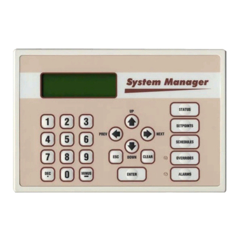
System Manager
The microprocessor based System Manager allows multiple Zone Managers and any
single-zone constant volume HVAC units to be programmed and monitored from a
central operator's panel. The System Manager is connected via the Auto-Zone Plus
communication network.
The System Manager is mounted in an attractive, white plastic housing, suitable for wall
mounting. A four line by twenty character backlighted LCD display and membrane
keypad provide a user friendly interface. All system variables, setpoints, and values can
be viewed and modified from the System Manager. Menu driven programming makes the
Auto-Zone Plus easy to set up and operate without the need for specialized training.
firealarmresources.com

Section 1
Auto-Zone Plus
1-4 Design Guide
CommLink II
The CommLink II communications interface allows user access to any controller.
Locally, access is by means of an on-site computer. Remote access is obtained via
modem. The CommLink II may also be configured for Call-Out on Alarm. The
CommLink II comes packaged in an attractive plastic enclosure and is powered by a
small wall mounted transformer. The CommLink II should be located near the computer
which will be used to monitor the system. If no on-site computer is to be used then locate
the CommLink II near the phone line jack if a modem is to be used. The cables from the
CommLink II-to-modem and the CommLink II-to-computer should not exceed twenty-
five feet.
Zone Manager
The Zone Manager is a microprocessor based controller which monitors up to sixteen
zones in the system. The zone manager then controls the HVAC unit to satisfy the
requirements of each individual zone while maintaining efficient operation and comfort.
The Zone Manager operates the fan, heating, cooling, duct static pressure, and
economizer functions. Each Zone Manager also features time scheduling, night set back,
trend logging of sensor values, and automatic changeover.
Bypass Damper
The bypass damper controls proper duct static pressure to insure proper airflow. The
damper is modulated by the Zone Manager, based on a signal received from the static
pressure sensor connected to the main duct.
Zone Controller
The Zone Controller monitors space temperature and allocates proper airflow to the
assigned zone to achieve desired comfort and ventilation levels. If supply air temperature
will benefit the local zone temperature setpoint, the zone damper modulates to reduce or
increase airflow as needed. If supply air will not benefit the local zone, the controller will
direct the damper actuator to a minimum position and wait for a change in supply air
temperature.
Constant Volume Controller
The Constant Volume (CV) Controller is a microprocessor based controller designed to
operate packaged roof top HVAC units. Up to thirteen stand alone CV controllers can be
connected to each Zone Manager's local communications loop to provide a fully
integrated multizone/single-zone control system. The CV controller operates the fan,
heating, cooling, and economizer functions. Each CV controller also features time
scheduling, night set back, trend logging of sensor values, and automatic changeover.
firealarmresources.com

Auto-Zone Plus
Section 1
Design Guide 1-5
Zone Sensor
The patented zone sensor is of a flush, wall mounted design. A special plate on the face
of the sensor accurately senses space conditions. As a result of its unique design, the zone
sensor rejects the influence of internal wall temperature effects. The sensor comes in four
different configurations:
•Sensor only
•Sensor w/push-button override (override is fixed at 2 hours)
•Sensor w/setpoint adjustment
•Sensor w/override & setpoint adjustment
Any combination of these sensor configurations can be used with the system.
firealarmresources.com

Section 1
Auto-Zone Plus
1-6 Design Guide
Design Considerations
Consider the following items when designing an Auto-Zone Plus system.
Zone Diversity
An Auto-Zone Plus system is designed to improve tenant comfort by dynamically re-
balancing the air distribution when used with a typical constant volume rooftop
heating/cooling unit. If zones with extremely different load conditions are serviced by a
single rooftop unit, the result will be poor control and excessive wear due to cycling of
the equipment.
It is especially important to avoid mixing interior zones (which require cooling all year)
with exterior zones (which may require constant heat during winter months). If you must
mix zones under these conditions, consider using either VAV boxes with heat or separate
baseboard heat on exterior zones. Auto-Zone Plus systems offer a variety of methods to
control additional zone heat to help you avoid problems.
Group similar loads on an individual unit and use more than one zoned unit if required.
Any special loads can be handled by using separate constant volume units.
The Auto-Zone Plus system offers the designer considerable flexibility by allowing both
multiple-zoned units and single-zone units to be connected within a single simple system.
Cooling - Partial Load Conditions
The engineer must be aware of several potential problems when applying an Auto-Zone
Plus system during cold weather operation.
Low Ambient Temperature Lockout
During very cold weather it is common for mechanical systems to have “low temp
lockouts” which protect equipment from damage if operated under these conditions.
Auto-Zone Plus also provides user programmed lockouts for protection purposes,
although mechanical safeties should always be used as the final stage of protection.
If the rooftop unit services interior zones with thermal loads which require cooling when
outside temperatures are below the safe operating limits for your equipment, you should
seriously consider installing an economizer on your rooftop unit. The Auto-Zone Plus
control system is designed to take Plus of an economizer if it is installed. The use of an
economizer will save money on utilities and provide comfort under conditions when it is
not possible to operate the mechanical cooling system.
firealarmresources.com

Auto-Zone Plus
Section 1
Design Guide 1-7
Low Supply Air Temperatures
Under lightly loaded conditions much of the supply air may be bypassed back into the
return airside of the system. This bypassing will result in the lowering of the supply air
temperature, which may result in the supply air temperature reaching the low temp safety
limit. If the supply air low temp safety limit is exceeded, the control system will “cut-off”
the mechanical cooling to protect it from damage. Excessive cycling of the mechanical
system will result if this condition persists. Comfort may also suffer if the system cannot
run long enough to satisfy cooling demands.
A number of things can be done to reduce this problem. Some of these things depend
upon the type of installation.
•Avoid oversizing the unit. Do your load calculations carefully. Since Auto-Zone Plus
directs the heating or cooling to the zones which require it, you may find that you can
use a smaller unit in many cases. Oversizing is the number one cause of excessive
low supply air temperature cycling.
•Increase your cooling minimum airflow or damper position settings to allow more air
during cooling operation. Be careful to avoid settings which are so high you cause
over cooling of the spaces. Find a compromise position.
•Bypass the air into the plenum instead of into the return air intake. Be careful if you
use this method since you may get “dumping” of cold air from your return air grilles.
This method works best with plenum returns, do not use this method with ducted
returns unless you have carefully considered the consequences.
•Increase your static pressure setpoint to help reduce the amount of air being bypassed.
Be aware of increased noise levels and the cost of operation if you use excessive
static pressures. This will not work if you are using pressure independent zone
controllers, since they will maintain a constant flow of air to the zones regardless of
duct static pressure. This technique will likely cause over cooling of the spaces due to
increased airflows at minimum positions.
Warning: If the fan system has the capability of producing static pressures
which could damage ductwork you must provide a manual reset,
high pressure limit switch to cut-off the fan system in the event of
high duct static.
Do not use your Auto-Zone Plus system as a safety
device!
•Use an Economizer. Although this is not a cure-all, it greatly improves operation
during cool weather when cooling loads are minimal. Using an Economizer also
improves ventilation and lowers operating costs.
firealarmresources.com

Section 1
Auto-Zone Plus
1-8 Design Guide
Heating - Partial Load Conditions
Heating difficulties are less common than cooling difficulties. They are similar in nature,
however, and the cures are generally the same.
•Increase the Heating minimum setpoints on as many zones as possible.
•Increase the static pressure setting as high as is practical. Increasing static pressure
does not help if you are using pressure independent operation.
•Bypass to plenum instead of the return air intake if acceptable.
•Do not oversize your equipment.
•Use auxiliary heat in either your VAV boxes or baseboard.
Auto-Zone Plus has a number of auxiliary heat control options which provide solutions to
most problems. Refer to the Auxiliary Heat Control Options topic near the end of this
section.
Override Conditions
After-hours overrides can produce aggravated partial load conditions in both the heating
and cooling modes. The problem is most commonly caused by a single zone being
overridden for after-hours use. This causes the rooftop equipment to operate for only one
zone. The Auto-Zone Plus system offers an improved solution to this common problem
by allowing a single override to trigger a group of zones via a “global” override. This
allows the system to operate with sufficient load to reduce cycling caused by light load
conditions.
Building Pressurization
If you are using an economizer, building pressurization must be addressed. Failure to
properly handle building pressurization may result in doors remaining open when the
economizer is operating. Pressurization problems can render economizer operation
useless. The following suggestions will help to avoid potential problems.
•Use powered exhaust when the system uses ducted returns. The return duct pressure
drop will cause most barometric relief dampers to function poorly or not at all. Auto-
Zone Plus has the ability to control a powered exhaust whenever the economizer is
operating.
•Use a separate building pressure control which operates a relief fan or dampers.
firealarmresources.com

Auto-Zone Plus
Section 1
Design Guide 1-9
Design Guide
There are six basic steps to designing an Auto-Zone Plus system:
1. Zoning
2. Sizing the Central Unit
3. Duct Design Considerations
4. Room Air Motion / Diffuser Selection
5. Bypass Damper Sizing
6. Sizing Zone Dampers
Step #1 - Zoning
Determine the number of zones. A single air handler unit can have no more than sixteen
zones. If the number of zones exceeds sixteen then more than one Zone Manager will be
required.
The primary precaution to be taken in applying the Auto-Zone Plus System is to select
the zoning so that no zone will be at maximum (design) heating (or cooling) load when
any other zone requires the opposite temperature air to satisfy its load. For example,
depending on the wall, ceiling and floor material and location within the building (e.g.
top or middle floor), a typical floor of a building usually has a minimum of nine distinct
temperature or control zones that are affected uniquely by the outdoor load. These zones
are depicted in Figure 1-2.
Depending on the size of the building and partition layout, some of these zones may
overlap or be insignificant from a zoning standpoint. For example, Zone 10 could be
multiple conference or computer rooms where additional zoning would be required, or it
could be as small as a corridor where no zoning is required. Similarly, zones 4 and 5
could have no external windows and no partitions between them and could be considered
a single zone. Zone 3 could be divided into multiple offices with full partitions between
them, thus requiring separate Zone Controllers because of different internal loads, but the
same external load.
Generally, the greater the number of individual Zone Controllers, the greater the comfort.
The designer will have to look at the specific building, balancing the costs of multiple
zones with the added comfort possible with multiple zones, to match the owner's
requirements.
firealarmresources.com

Section 1
Auto-Zone Plus
1-10 Design Guide
It is important to recognize that there are purely internal zones, such as Zone 10, which
may contain separate offices/conference/computer rooms. These internal zones could
easily have high cooling requirements while external zones (1,2,3, etc.) could be at or
near design heating load. This is a misapplication of the Auto-Zone Plus (or any
heating/cooling changeover) system. The interior zones with cooling only loads should
be served with a separate air-conditioning unit (that could be zoned between multiple
rooms with a similar load profile). Supplemental heat could be added to the perimeter
zones and controlled with the auxiliary heat control board from the Zone Controller.
System performance will generally be compromised and frequent changeover from the
heating to the cooling mode will occur during the heating season if purely internal zones
are combined on the same air-conditioning unit serving perimeter zones.
Figure 1-2: Control Zones Affected by the Outdoor Load
N
S
E
W
Room Sensor
(Typical)
Supply Air Duct
Supply Air Duct
Return Air Plenum
Return Air Plenum
Round Zone Damper
(Typical)
Bypass Damper
System Manager
Zoned HVAC Unit
Constant Volume HVAC Unit
1
4
2
5
3
6
9
8
0
7
Enter
Esc
*
Minus
Menu
Clear
Dec.
Alarm
Communication
Override
MANAGER
SYSTEM
Auto-ZonePlus
01/01/9703:38PMWED
OCCUPIED
NOALARMS
WATTMASTERCONTROLSINC.
NORMAL
OVR
W
A
R
M
E
R
C
O
O
L
E
R
NORMAL
OVR
W
A
R
M
E
R
C
O
O
L
E
R
NORMAL
OVR
W
A
R
M
E
R
C
O
O
L
E
R
NORMAL
OVR
W
A
R
M
E
R
C
O
O
L
E
R
NORMAL
OVR
W
A
R
M
E
R
C
O
O
L
E
R
NORMAL
OVR
W
A
R
M
E
R
C
O
O
L
E
R
1
3
2
4
5
6
8
9
10
7
firealarmresources.com

Auto-Zone Plus
Section 1
Design Guide 1-11
Step #2 - Sizing the Central Unit
Because the zones are controlled with variable air volume, it is unlikely that all zones
will be at design load at the same time. The zoning allows for the diversity of loads to be
taken into account and will often provide better comfort with a smaller HVAC unit.
In sizing the system, the individual zone loads should be calculated using any dependable
load estimating program. Because of diversity, the central unit should be selected for the
instantaneous peak load, not the sum of the peak loads, as would be done with a constant
volume single zone system. Consider the following when sizing the central unit.
•Size the peak cooling load based on the month and hour of the greatest total
building/system load.
•Heating should be sized for the lowest design temperature with an additional margin
for morning "pickup". This margin is generally recommended to be 20 to 25 percent
of base design.
Step #3 - Duct Design Considerations
The AZ Plus system uses a typical low pressure duct design. To reduce noise problems
duct pressures should not exceed 1 inch W.C.
Primary trunk ducts should not be "undersized." This is especially true for "pressure
dependent" systems. Pressure dependent refers to the typical Plus Zone Controller without
the airflow sensor. With larger trunk ducts, it is easier to assure relatively constant
pressure to each zone. Runs should be as short as possible, and the trunk duct system kept
as symmetrical as possible to facilitate system balancing. Wherever possible, run the trunk
ducts above corridors and locate the zone dampers above corridors to reduce the noise in
the space and facilitate service of the units. Trunk ducts should be sized for no more than
0.1 inch W.C. drop per 100 feet, and a maximum duct velocity of 2000 FPM.
Note: For pressure independent terminal units with velocity sensors and
conventional "VAV" boxes properly selected for "quiet" operation, this 2000
FPM rule can be exceeded by up to 50 percent. The designer, however, should
be very experienced in VAV system design before considering modification
of this general rule.
Typical VAV systems with pressure independent terminals use the static regain method
for sizing ducts. The typical Auto-Zone Plus system is a low-pressure, pressure
dependent system that utilizes conventional unitary air-conditioning units. These systems
should use the equal-friction method of sizing the ducts, and use the maximum loss of 0.1
inch per 100 feet as described above.
firealarmresources.com

Section 1
Auto-Zone Plus
1-12 Design Guide
Step #4 - Room Air Motion/Diffuser
Selection
Air motion is a consideration for occupant comfort. The selection of diffusers for an
Auto-Zone Plus system requires more care than a constant volume system due to varying
flow of air into the zones. Slot diffusers are recommended due to their superior
performance at low airflows. Because the zone air flow is variable volume, lower cost
round or rectangular diffusers that were satisfactory for constant volume may prove
unsatisfactory with an Auto-Zone Plus system. These diffusers may result in "dumping"
of the cold air at low flows in the cooling mode, and insufficient room air motion at low
air flows in the heating mode. Although high air motion in the heating mode can be
undesirable, a slot diffuser with a high induction ratio generally helps to reduce room air
"stratification" when the heating comes from a ceiling diffuser. Linear slot diffusers
should be properly selected for the airflow and "throw" suited to the specific installation
or zone.
Additional factors to consider in diffuser selection is sound level and throw at design
flow. Generally, multiple diffusers will result in lower sound levels in the space, but this
must be balanced with the additional hardware and installation costs. It is commonly
recommended that slot diffusers be located near the perimeter or outside wall with the
airflow directed into the room. Consult your diffuser supplier or catalog for proper
diffuser sizing and location.
Series fan boxes may be used instead of zone dampers where higher induction rates are
desirable. If the heat loss on perimeter walls is high, such as large areas of glass, the use
of Series Fan Boxes may be indicated to maintain higher induction rates to offset
“downdrafts.” If the heat loss is greater than 275 BTUH/LINEAR FOOT, you should use
high quality slot diffusers next to the outer wall with the airflow directed inward to
counteract downdrafts during heating. Serious downdraft problems occur when heat
losses exceed 400 BTUH/LINEAR FOOT and both high induction diffusers and series
fan boxes are recommended.
firealarmresources.com

Auto-Zone Plus
Section 1
Design Guide 1-13
Step #5 - Bypass Damper Sizing
Using a load calculation program, the bypass damper should be sized to give you the
maximum CFM of air to be bypassed, typically 60 to 70 percent of the HVAC units rated
capacity.
To size the damper, select a damper from the table based on calculated bypass CFM and
a maximum velocity between 1750-2250 FPM. When determining the bypass duct size,
be sure to take into account any transition fittings and associated pressure drops. (See
Table 1-1: Damper Sizing Chart)
Whenever possible, use a single bypass damper and round duct for the bypass. If space
limitations or total airflow requires it, multiple bypass dampers can be controlled in
parallel.
For proper control of the Bypass Damper, the static pressure sensor location is very
important. Refer to Figure 1-3: Locating the Static Pressure Sensor for Bypass
Damper Control for proper mounting locations.
firealarmresources.com

Section 1
Auto-Zone Plus
1-14 Design Guide
Preferred Location
If the trunk ducts are properly
sized for minimum pressure drop,
the location of the static pickup
probe is not particularly critical. It
should ideally be located at right
angles to the airflow in a straight
section of the supply duct
approximately 2/3 the distance of
the total length of the supply duct.
Also the probe should be located
not less than 3 duct diameters
downstream and 2 duct diameters
upstream of any elbow or takeoff.
Fan
RA Sensor
SA Sensor
3D
Min.
2D
Min.
Return Air Duct
Supply Air Duct
SP Pickup
Bypass Damper
SP Sensor
Less Than Ideal, But
Acceptable
Since the "ideal" location is often
difficult to find in an installation, a
location in the main trunk where
the tip is not in a "negative
pressure area" (e.g. just
downstream of the inside curve of
an elbow) or an area where the
tube opening is directly impacted
by the velocity of the supply air.
Fan
RA Sensor
SA Sensor
Return Air Duct
Supply Air Duct
SP Pickup
Bypass Damper
SP Sensor
Least Desirable, But
Acceptable
If the supply duct comes directly
from the unit and immediately
splits in opposite directions, the
pressure pickup should be located
ahead of the split, or as close to it
as possible, even if the bypass
damper(s) are located downstream
of the split.
Fan
RA Sensor
SA Sensor
Return Air Duct
Supply Air Duct
Tubing To Be Equal
Length And Size
Bypass Damper
SP Sensor
SP Pickups
Figure 1-3: Locating the Static Pressure Sensor for Bypass Damper Control
firealarmresources.com
Table of contents
Other WattMaster Control System manuals

