4
www.vintageair.com
901441 REV B 1/30/19, PG 4 OF 9
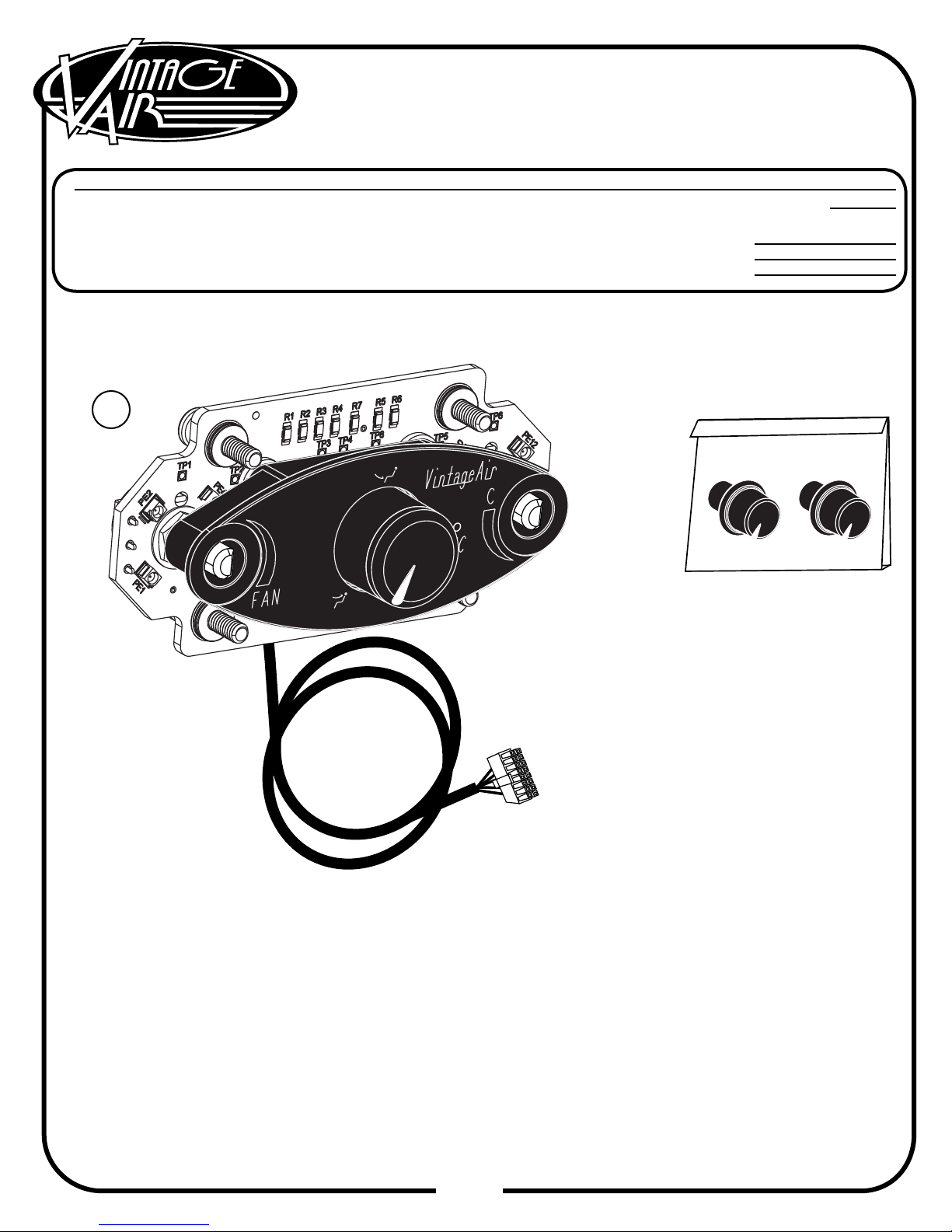
Control Panel Dimensions
Control Panel Installation
Select a suitable location for the control panel, considering heater control valve location, wiring harness
length and operator convenience.
After selecting a location for the control panel, mask the area 1 ½” (tall) x 4 ½” (wide).
Using the dimensions provided above, mark or scribe the control panel opening location onto the dash.
When you are certain that the dimensions and markings are correct, cut the dash to make the control
panel opening. NOTE: Measure twice. Cut once. This opening MUST be a precise t. Cut the opening
undersize, and then le to t. The mounting screws only hold the panel against the dash. They do
not locate the panel laterally. If the opening is oversized, the panel may shift during use.
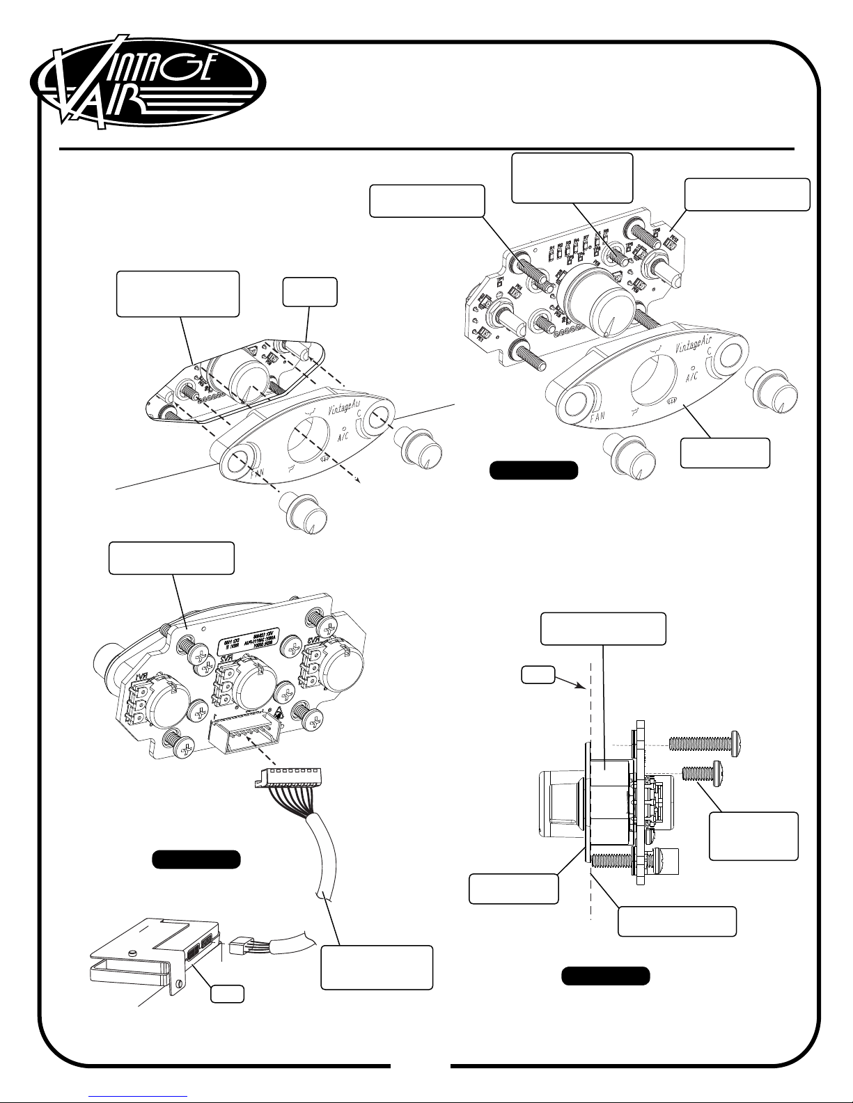
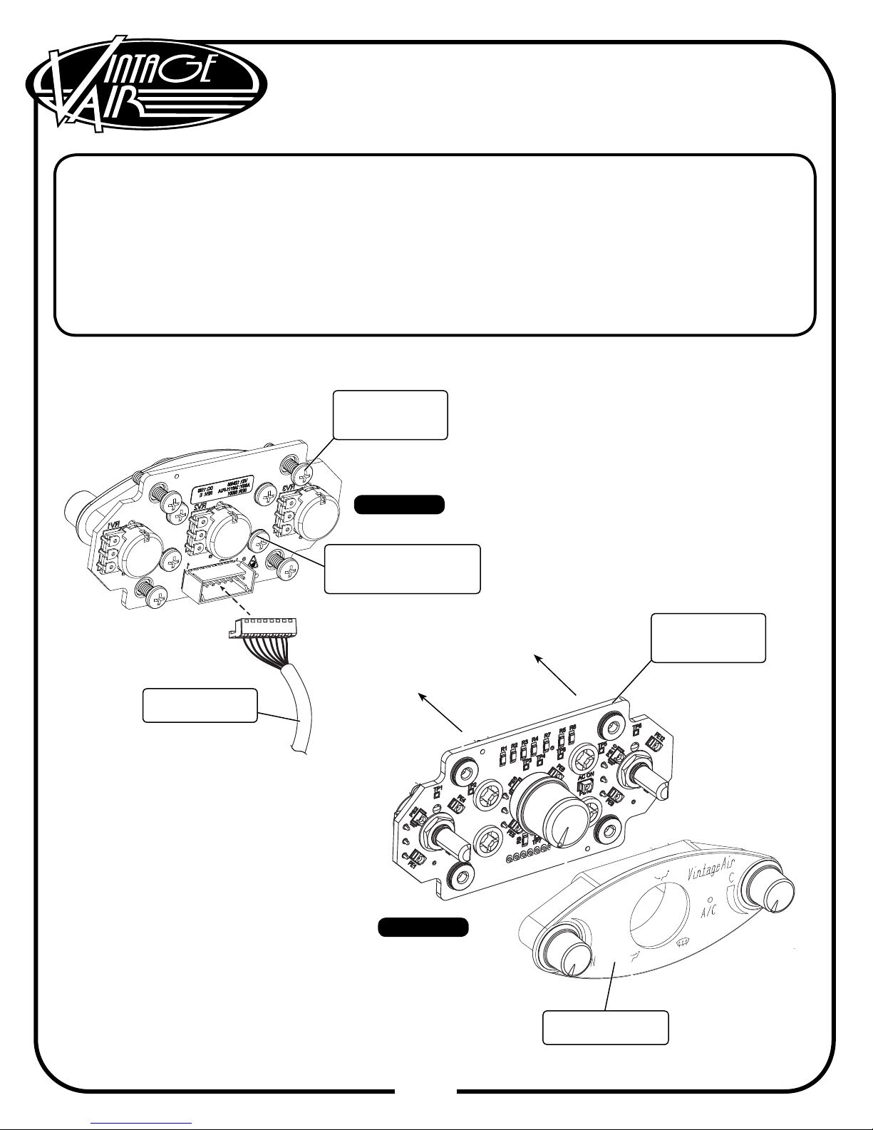
Install the control panel face through the opening in the dash. Place the control panel PC board assembly
behind the dash, and secure it to the control panel face using the (4) 8-32 x 3/8” screws (See Figure 1 and
2a, Page 5). NOTE: When tightening the control panel mounting screws, hand tighten until the
screw contacts the back side of the dash. Then, using a screwdriver, tighten an additional 1/2
turn. Do not overtighten, as this may cause damage to the PC board or the dash.
Install the control panel knobs (See Figure 1, Page 5).
Plug the control panel wiring harness into the control panel and the ECU on the evaporator (See Figure 2,
Page 5).
Wire according to the wiring diagram on Page 7.
1.
2.
3.
4.
5.
6.
7.
3.3175”
1.440” Ø.3438 (11/32)”
Ø.4375 (7/16)”
NOTE: Do not install the (2) control panel knobs onto the control panel assembly until the panel has
been installed in the dash. For knob removal after installation, refer to the Control Panel Removal
instructions on Page 6. DO NOT attempt to remove the knobs using pliers.
2.880”
Level This Line
1.0438” .700”