manuals.online logo
Brands
  1. Home
  2. •
  3. Brands
  4. •
  5. wattstopper
  6. •
  7. Accessories
  8. •
  9. wattstopper CX-100 User manual

wattstopper CX-100 User manual

SSENSOR ADJUSTMENT
THE SENSORS ARE FACTORY PRESET*TO ALLOW FOR QUICK INSTALLATION IN
MOST APPLICATIONS. However, verification of proper wiring or coverage, or customizing
of the sensor’s settings can be done through the following steps.
Before starting, make sure the office furniture is installed, lighting circuits are turned on,
and the HVAC systems are in the overridden/on position. VAV systems should be set to
their highest airflow.
There is a warm-up period when power is first
applied to the sensor of up to one and a half
minutes.
1. For testing, set the Time Delay to minimum, 15 seconds.
See chart below for DIP switch configurations.
2. Ensure that the Sensitivity and Light Level trimpots
are set to maximum, fully clockwise.
3. Remain still. The lights should turn off after
approximately 15 seconds (If not, see Troubleshooting).
4. Set the desired Time Delay.
5. Readjust the angle of the sensor if necessary.
Time Delay:
• The Time Delay is set with DIP Switches 1 thru 4.
Light Level feature:
• The Light Level feature holds lights off upon initial
entry into the space if adequate ambient light exists.
It will not turn the lights off if they are on.
• Adjust the Light Level during daylight hours when
ambient light in the area is adequate.
• Avoid mounting the sensor too close to lighting fixtures.
1. Set the Time Delay to minimum, 15 seconds.
2. Set the Light Level trimpot to minimum,
fully counterclockwise.
3. Be still and allow the lights to turn off.
4. Move a hand in front of sensor every 10 seconds (to
keep sensor activated), and without blocking any light
from reaching the sensor, in small increments, turn
Light Level adjustment toward maximum, waiting at
least 5 seconds between increments, until the lights
turn on. Then turn it back slightly. At this setting the
lights will not turn on with occupancy if the ambient
light is above the current level.
5. Set the desired Time Delay.
6. Readjust the angle of the sensor if necessary.
*Time Delay=18 minutes / Sensitivity & Light Level settings=Maximum.
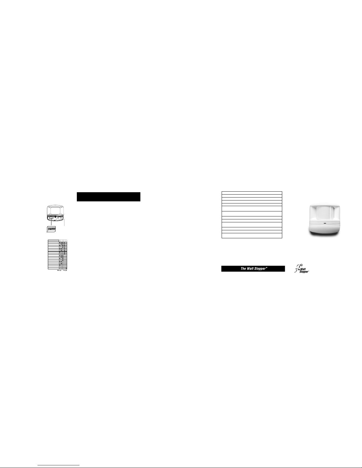
Light Level
Adjustment
LED
Sensitivity
Adjustment
Time-Delay
DIP Switch
on
25431
✆Call (800) 879-8585 For Technical Support ✆
STROUBLESHOOTING
Lights do not turn on with occupancy, and the following condition exists:
• LED does NOT flash:
When power is initially applied to the sensor, there is a warm-up period of up to
60 seconds before the LED is active.
1. Check that the circuit breaker has been turned back on.
2. Check the Sensitivity settings. Increase (clockwise) as needed.
3. Check all sensor and power pack wire connections.
4. Check for 24VDC at sensor (violet and green or gray wires).
- If 24VDC is present, replace the sensor.
- If 24VDC is not present, check that high voltage is present to power pack.
If it is, replace power pack.
• LED does flash:
1. The Light Level setting or the Sensitivity may be set too low.
2. If the sensor’s Light Level feature has been utilized, the lights connected to the Light
Level Output might be held off because of the level of ambient light in the
controlled area.
- To test whether the Light Level adjustment is the problem, cover the PIR lens
with your hand for 5 seconds to see if the lights turn on, or turn the Light Level
adjustment toward maximum (clockwise). If the lights turn on, the Light Level
setting was keeping the lights off.
• Increase the Light Level setting slightly or follow the procedures under
“Sensor Adjustment” to adjust the Light Level setting.
- The Sensitivity adjustment should be set to maximum, unless a decrease is made
due to an “Unwanted Sensor Activations” adjustment.
3. Check all sensor and power pack wire connections.
4. Check for 24VDC at the power pack’s blue wire connection to sensor while
someone moves in front of sensor to activate the LED. If there is no voltage,
replace the sensor. If there is voltage, replace the power pack.
≠CAUTION≠
TURN POWER OFF AT THE CIRCUIT BREAKER
BEFORE WORKING WITH OR NEAR HIGH VOLTAGE.
Check Our Web Site For FAQs: www.wattstopper.com
Lights do not turn off automatically:
1. The sensor may be experiencing activations from outside the controlled area or
from some type of interference (see “Unwanted Sensor Activations” next page).
2. Check all sensor and power pack wire connections.
3. Disconnect power pack’s blue wire:
If the lights do not turn off, replace power pack. Reconnect blue wire.
If the lights turn off, the problem may be in the sensor—to check:
- Reconnect the blue wire.
- Turn sensitivity and time delay to minimum and allow the sensor to time out.
If the lights turn off, the sensor is working properly (see number 1., above, and
“Sensor Adjustment” for readjustment of sensor).
Unwanted Sensor Activations (LED flashes):
• Possible causes
1. Improper sensor location or angle adjustment causing detection outside of desired
coverage area.
2. Sensitivity set too high.
3. Sensor located too close to HVAC or VAV vents with heavy air flow.
• Possible solutions
1. Mask the lens to reduce PIR coverage (see “Masking the lens”, under “Coverage
Patterns”).
2. Reduce the sensitivity (counterclockwise) as needed (see “Sensor Adjustment”).
3. Adjust the sensor angle (see “Sensor Adjustment”).
4. Relocate the sensor.
Override:
To override all sensor functions, set DIP switch #5 to on.
This bypasses the occupancy and light level control functions of the sensor, but still allows
the lights to be manually controlled with a light switch.
SORDERING INFORMATION
A277E-P
A347D-P
CX-100-3 Occupancy Sensor, Two-Sided Aisleway Lens
MB-1 Industrial Mount Bracket
Power Pack: 277VAC, 60Hz, 20A ballast, 100mA
Power Pack: 347VAC, 60Hz, 15A ballast, 100mA
CX-100
CX-100-1
Occupancy Sensor, Dense Wide Angle Lens (Std)
Occupancy Sensor, Long Range Lens
CX-100-4 Occupancy Sensor, One-Sided Aisleway Lens
A120E-P Power Pack: 120VAC, 60Hz, 100mA
20A ballast/13A incandescent
B230E-P Power Pack: 230VAC, 50/60Hz, 150mA
20A ballast/13A incandescent
B120E-P Power Pack: 120VAC, 60Hz, 150mA
20A ballast/13A incandescent
B347D-P
S120/277/347E-P
Power Pack: 347VAC, 60Hz, 15A ballast, 150mA
B277E-P Power Pack: 277VAC, 60Hz, 20A ballast, 150mA
Slave Pack: 120/277VAC, 60Hz, 20A ballast
347VAC, 60Hz, 15A ballast
Putting a Stop to Energy Waste®
Santa Clara CA 95050 1(800)879-8585 1(972)578-1699
70-0004-00 4/98
SWARRANTY INFORMATION
The Watt Stopper, Inc. warranties its products to be free of defects in materials and
workmanship for a period of five years. There are no obligations or liabilities on the part of
The Watt Stopper, Inc. for consequential damages arising out of or in connection with the
use or performance of this product or other indirect damages with respect to loss of
property, revenue, or profit, or cost of removal, installation or reinstallation.
Installation Instructions
CX-100
PIR Occupancy Sensor
Santa Clara, CA 95050
1(800) 879-8585 1(972)578-1699
www.wattstopper.com
U.S.Patent:
4,787,722
SSPECIFICATIONS
Voltage . . . . . . . . . . . . . . . . . . . . . . . . . . . . . . . . . . . . . . . . . . . . . 24VDC
Current Consumption . . . . . . . . . . . . . . . . . . . . . . . . . . . . . . . . . . 19mA*
Power Supply . . . . . . . . . . . . . . . . . . . . . . . . . . Watt Stopper Power Pack
B series power packs supply power for up to 6 CX-100 sensors
A series power packs supply power for up to 3 CX-100 sensors
Isolated Relay Rating . . . . . . . . . . . . . . . . . . . . . . . . . . . . . . . 1A@24VDC
Time Adjustment . . . . . . . . . . . . . . . . . . . . . . . . . 15 seconds–30 minutes
Sensitivity Adjustment . . . . . . . . . . . . . . . . . . . . . . . . Minimum–Maximum
Light Level Adjustment . . . . . . . . . . . . . . . . . . . . . . . . . . . . . . . . 3–200FC
*Current consumption can be slightly higher when only one sensor per power pack is used.
✆Call (800) 879-8585 For Technical Support ✆
All sensors are white.
15 seconds
4 minutes
6 minutes
8 minutes
10 minutes
12 minutes
14 minutes
2 minutes
16 minutes
20 minutes
22 minutes
24 minutes
26 minutes
28 minutes
30 minutes
Override
18 minutes
12345
DIP Switch #
Time Delays
.
.=factory preset
Check Our Web Site For FAQs: www.wattstopper.com
Isolated Relay Outputs
Normally Closed Contact
Common
Normally Open Contact
Wires
BRN
RED
ORN
YEL
GRN
BLU
VIO
GRA
Control Output 24VDC
Common
+24VDC
Light Level Output 24VDC
White (Neutral)
Red (Load)
Red (Line)
White
BlackHot
N
Light
Level
Lighting
Load
SLAVE
PACK
Red (load)
Hot OFF switch
Black
Blue
Red
Black
Blue
Switch
Common
N
Lighting
Load
POWER PACK
White (Neutral)
Red (Load)
Red (Line)
White
BlackHot
NPOWER PACK
Red
Black
Blue
Switch
Control Output 24VDC (YEL)
+24VDC (VIO)
Lighting
Load
White (Neutral)
Red (Load)
Red (Line)
White
Black
Hot
N
POWER PACK
Red
Black
Blue
Switch
Common (GRN)
Control Output 24VDC (YEL)
+24VDC (VIO)
Common (GRN)
Lighting
Load
Occupancy and
Light Level
Controlled
Lighting
Multiple Sensors
and Lighting
✆Call (800) 879-8585 For Technical Support ✆
SWIRING DIRECTIONS
≠CAUTION≠
TURN POWER OFF AT THE CIRCUIT BREAKER
BEFORE INSTALLING POWER PACKS OR SENSORS.
Each Watt Stopper B series power pack can supply power for up to 6 CX-100 sensors.
Each Watt Stopper A series power pack can supply power for up to 3 CX-100 sensors.
When using more sensors than this, multiple power packs are required.
REFER TO THE WIRING DIAGRAMS ON THE NEXT PAGE FOR THE FOLLOWING
PROCEDURES:
FIRST—connect the low voltage:
• RED wire (+24VDC) from power pack to VIOLET wire on sensor.
• BLACK wire (Return) from power pack to GREEN wire on sensor.
Wiring a SINGLE LIGHTING LOAD CONTROLLED BY OCCUPANCY ONLY—
connect:
• BLUE wire from power pack to YELLOW wire on sensor.
Wiring a SINGLE LIGHTING LOAD CONTROLLED BY OCCUPANCY, DEPENDENT
ON LIGHT LEVEL (AMBIENT LIGHT)—connect:
• BLUE wire from power pack to BLUE wire on sensor.
Wiring ONE LIGHTING LOAD FOR OCCUPANCY CONTROL, AND A SECOND
LOAD FOR OCCUPANCY AND LIGHT LEVEL (AMBIENT LIGHT) CONTROL—
connect:
• BLUE wire from power pack to YELLOW wire on sensor.
• BLUE wire from slave pack to BLUE wire on sensor.
• BLACK wire from slave pack to GRAY wire on sensor.
Wiring the ISOLATED RELAY: (The Isolated Relay is rated for 1A @24VDC)
Connect the wires necessary to the application that requires this output.
• RED (Common) (must be used for proper operation)
• BROWN (Normally Closed)—Open when occupancy is detected
• ORANGE (Normally Open)—Closed when occupancy is detected
PARALLEL
to VERTICAL
at 10 foot
mounting
height
PARALLEL
to WALL
at 10 foot
mounting
height
Reference
Surface
Angle
Ceiling Mounted
Wall Mounted
fig. B
SINSTALLATION
The CX-100 sensors can be mounted
to walls or ceilings with the supplied
swivel bracket, and the supplied junction
box cover plate if necessary (see figure C).
Mounting at fixture height is most effective.
The -3 & -4 sensors can also be mounted
to industrial fixtures by using the MB-1
industrial mount bracket.
Mounting
Ceiling: It is best to leave approximately
six inches between the sensor and the wall so that
the Tightening Screw can be easily accessed. Orient the
Base Bracket’s Half-Circle Notch in the direction that the
sensor will point.
Wall: Orient the Base Bracket’s Half-Circle Notch, up.
Procedures:
1. Mount the Base Bracket to the mounting surface with screws.
2. At the center of the Base Bracket, drill a hole in the ceiling or wall (unless mounting to
a junction box) large enough to thread the sensor’s wires through.
3. Guide the sensor’s wires into the Base Bracket and through the hole in the ceiling or wall.
4. Connect the sensor to the Base Bracket by angling the Post Bracket so that it is in line
with the half circle notch, as illustrated in figure A. Push the ball into the Base Bracket
opening until it snaps into place, being careful not to pinch the wires. The brackets can
be easily connected or disconnected using this orientation.
5. Insert the Tightening Screw and Nut into the Base Bracket as illustrated.
Half-Circle
Notch
Base
Bracket
Reference
Surface
Angle
Post
Bracket
Nut
fig. A
Tightening
Screw
✆Call (800) 879-8585 For Technical Support ✆Check Our Web Site For FAQs: www.wattstopper.com
6. Use the Reference Surface Angle to
adjust the sensor for optimum
coverage. When mounted at ten feet,
the Reference Surface Angle should
be parallel to the wall or the vertical
(see figure B). (As the mounting
height decreases, the sensor will be
tilted up slightly; as the mounting
height increases, the sensor will be
tilted down slightly).
7. Tighten the Tightening Screw.
Industrial Mount Bracket MB-1
In an industrial setting, the MB-1 can be used to
mount the CX-100-3 or CX-100-4 to a variety of
structures or fixtures, including fluorescent
fixtures.
The MB-1 features an L-shaped bracket
and sensor housing. The housing can be
positioned so that the sensor’s view is
straight down (CX-100-3), or
directioned down an aisle
(CX-100-4).
When mounting the CX-100-4
with the MB-1 bracket fully
rotated, the coverage pattern
will extend slightly behind the
sensor’s mounting position
(see, Coverage Patterns). The
chart at right can help to position
the MB-1 for the coverage desired.
Sensor Angle Adjustment
While watching the PIR sensing indicator
(red LED) for flashes, have a person walk
back and forth at the far end of the space.
Increase or decrease mounting angle as
needed until the desired coverage is
achieved.
Tighten the Tightening Screw to hold this position.
CX-100-4
MB-1
Mounting Distance of
height coverage behind
12' 2.5'
18' 4'
24' 5'
30' 6.5'
10ft
0
8ft
8ft
16ft
16ft
0
10 15ft 55ft 85 90ft
TOP
SIDE
Long Range Lens (-1)
up to 90 linear ft for walking motion
SUNIT DESCRIPTION
The CX-100 is a 24VDC passive infrared (PIR) occupancy sensor which controls lighting
and HVAC systems based on occupancy and has a light level feature that can be used to
keep sections of lights from turning on if the ambient light level is sufficient. The CX-100
contains an isolated relay with Normally Open and Normally Closed outputs for interfacing
with HVAC or EMS.
PIR sensing systems are passive systems which react to changes in infrared energy (moving
body heat) within the coverage area. PIR sensors must directly “see” motion of an occupant
to detect them, so careful consideration must be given to sensor placement.
SCOVERAGE PATTERNS
Coverages shown are maximum and represent coverage for walking motion. Actual coverage
will vary slightly depending on mounting height and furnishings.
Masking the lens: Opaque adhesive tape is supplied so that sections of the sensor’s lens
can be masked. This restricts the sensor’s view and allows you to eliminate coverage in
unwanted areas.
0
3 ft
30ft
0
15ft
10 ft 10 ft 20 ft 30 ft 40 ft 50 ft0
33°using MB-1 with
maximum rotation
TOP
SIDE
One-Sided Aisleway Lens (-4)
up to 50 linear ft for walking motion
Check Our Web Site For FAQs: www.wattstopper.com
30ft
0
67ft 67ft38ft 38ft21ft 21ft10ft 10ft0
0
5ft
15ft
15ft
0
33.5ft 33.5ft
SIDE
TOP
Two-Sided Aisleway Lens (-3)
up to 134 linear ft for walking motion
SIDE
TOP
10ft
7ft 15ft 25ft 55ft0
50ft.
55ft.
Dense Wide Angle Lens (Standard)
up to 2000 sq ft for walking motion
up to 1000 sq ft for desktop motion
Junction Box
with Mud-Ring
Junction Box
Cover Plate
Ceiling
Swivel Bracket
Predrilled
Holes
Junction Box Cover Plate Installation
fig. C
SSENSOR ADJUSTMENT
THE SENSORS ARE FACTORY PRESET*TO ALLOW FOR QUICK INSTALLATION IN
MOST APPLICATIONS. However, verification of proper wiring or coverage, or customizing
of the sensor’s settings can be done through the following steps.
Before starting, make sure the office furniture is
installed, lighting circuits are turned on, and the
HVAC systems are in the overridden/on position.
VAV systems should be set to their highest
airflow.
There is a warm-up period when power is
first applied to the sensor of up to one and a
half minutes.
1. For testing, set the Time Delay to minimum,
15 seconds. See chart below for DIP switch
configurations.
2. Ensure that the Sensitivity trimpot is set to
maximum, fully clockwise.
3. Remain still. The lights should turn off after
approximately 15 seconds (If not, see
Troubleshooting).
4. Set the desired Time Delay.
5. Readjust the angle of the sensor if necessary.
Time Delay:
• The Time Delay is set with DIP Switches
1 thru 4.
*Time Delay=18 minutes
Sensitivity settings=Maximum.
LED
Sensitivity
Adjustment
Time-Delay
DIP Switch
on
25431
✆Call (800) 879-8585 For Technical Support ✆
STROUBLESHOOTING
Lights do not turn on with occupancy, and the following condition exists:
• LED does NOT flash:
When power is initially applied to the sensor, there is a warm-up period of up to
60 seconds before the LED is active.
1. Check that the circuit breaker has been turned back on.
2. Check the Sensitivity setting. Increase (clockwise) as needed.
3. Check all sensor and power pack wire connections.
4. Check for 24VDC at sensor (red or black wires).
- If 24VDC is present, replace the sensor.
- If 24VDC is not present, check that high voltage is present to power pack.
If it is, replace power pack.
• LED does flash:
1. Check all sensor and power pack wire connections.
2. Check for 24VDC at the power pack’s blue wire connection to sensor while someone
moves in front of sensor to activate the LED. If there is no voltage, replace the sensor.
If there is voltage, replace the power pack.
Lights do not turn off automatically:
1. The sensor may be experiencing activations from outside the controlled area or
from some type of interference (see “Unwanted Sensor Activations” next page).
2. Check all sensor and power pack wire connections.
3. Disconnect power pack’s blue wire:
If the lights do not turn off, replace power pack. Reconnect blue wire.
If the lights turn off, the problem may be in the sensor—to check:
- Reconnect the blue wire.
- Turn sensitivity and time delay to minimum and allow the sensor to time out.
If the lights turn off, the sensor is working properly (see number 1. above, and
“Sensor Adjustment” for readjustment of sensor).
≠CAUTION≠
TURN POWER OFF AT THE CIRCUIT BREAKER
BEFORE WORKING WITH OR NEAR HIGH VOLTAGE.
Check Our Web Site For FAQs: www.wattstopper.com ✆Call (800) 879-8585 For Technical Support ✆
Unwanted Sensor Activations (LED flashes):
• Possible causes
1. Improper sensor location or angle adjustment causing detection outside of desired
coverage area.
2. Sensitivity set too high.
3. Sensor located too close to HVAC or VAV vents with heavy air flow.
• Possible solutions
1. Mask the lens to reduce PIR coverage (see “Masking the lens”, under “Coverage
Patterns”).
2. Reduce the sensitivity (counterclockwise) as needed (see “Sensor Adjustment”).
3. Adjust the sensor angle (see “Sensor Adjustment”).
4. Relocate the sensor.
Override:
To override all sensor functions, set DIP switch #5 to on.
This bypasses the occupancy control function of the sensor but still allows the lights to be
manually controlled with a toggle switch.
SORDERING INFORMATION
A277E-P
A347D-P
CX-105-3 Occupancy Sensor, Two-Sided Aisleway Lens
MB-1 Industrial Mount Bracket
Power Pack: 277VAC, 60Hz, 20A ballast, 100mA
Power Pack: 347VAC, 60Hz, 15A ballast, 100mA
CX-105
CX-105-1
Occupancy Sensor, Dense Wide Angle Lens (Std)
Occupancy Sensor, Long Range Lens
CX-105-4 Occupancy Sensor, One-Sided Aisleway Lens
A120E-P Power Pack: 120VAC, 60Hz, 100mA
20A ballast/13A incandescent
B230E-P Power Pack: 230VAC, 50/60Hz, 150mA
20A ballast/13A incandescent
B120E-P Power Pack: 120VAC, 60Hz, 150mA
20A ballast/13A incandescent
B347D-P
S120/277/347E-P
Power Pack: 347VAC, 60Hz, 15A ballast, 150mA
B277E-P Power Pack: 277VAC, 60Hz, 20A ballast, 150mA
Slave Pack: 120/277VAC, 60Hz, 20A ballast
347VAC, 60Hz, 15A ballast
All sensors are white.
Putting a Stop to Energy Waste®
Santa Clara CA 95050 1(800)879-8585 1(972)578-1699
70-0027-00 4/98
SWARRANTY INFORMATION
The Watt Stopper, Inc. warranties its products to be free of defects in materials and
workmanship for a period of five years. There are no obligations or liabilities on the part of
The Watt Stopper, Inc. for consequential damages arising out of or in connection with the
use or performance of this product or other indirect damages with respect to loss of
property, revenue, or profit, or cost of removal, installation or reinstallation.
Installation Instructions
CX-105
PIR Occupancy Sensor
U.S.Patent:
4,787,722
SSPECIFICATIONS
Voltage . . . . . . . . . . . . . . . . . . . . . . . . . . . . . . . . . . . . . . . . . . . . . 24VDC
Current Consumption . . . . . . . . . . . . . . . . . . . . . . . . . . . . . . . . . . . 8mA*
Power Supply . . . . . . . . . . . . . . . . . . . . . . . . . . Watt Stopper Power Pack
B series power packs supply power for up to 14 CX-105 sensors
A series power packs supply power for up to 8 CX-105 sensors
Time Adjustment . . . . . . . . . . . . . . . . . . . . . . . . . 15 seconds–30 minutes
Sensitivity Adjustment . . . . . . . . . . . . . . . . . . . . . . . . Minimum–Maximum
*Current consumption can be slightly higher when only one sensor per power pack is used.
15 seconds
4 minutes
6 minutes
8 minutes
10 minutes
12 minutes
14 minutes
2 minutes
16 minutes
20 minutes
22 minutes
24 minutes
26 minutes
28 minutes
30 minutes
Override
18 minutes
12345
DIP Switch #
Time Delays
.
.=factory preset
Santa Clara, CA 95050
1(800) 879-8585 1(972)578-1699
www.wattstopper.com
0
3 ft
30ft
0
15ft
10 ft 10 ft 20 ft 30 ft 40 ft 50 ft0
33°using MB-1 with
maximum rotation
✆Call (800) 879-8585 For Technical Support ✆
SWIRING DIRECTIONS
≠CAUTION≠
TURN POWER OFF AT THE CIRCUIT BREAKER
BEFORE INSTALLING POWER PACKS OR SENSORS.
Each Watt Stopper B series power pack can supply power for up to 14 CX-105 sensors.
Each Watt Stopper A series power pack can supply power for up to 8 CX-105 sensors.
When using more sensors than this, multiple power packs are required.
REFER TO THE WIRING DIAGRAMS ON THE NEXT PAGE FOR THE FOLLOWING
PROCEDURES:
Connect the low voltage:
• RED wire (+24VDC) from power pack to RED wire on sensor.
• BLACK wire from power pack to BLACK wire on sensor (Control Return) .
• BLUE wire from power pack to BLUE wire on sensor (Control Output 24VDC).
Control Output 24VDC
+24VDC
White (Neutral)
Red (Load)
Red (Line)
White
BlackHot
NPOWER PACK
Red
Black
Blue
Switch
Control Return
BLU
Wires
RED
BLK
Lighting
Load
White (Neutral)
Red (Load)
Red (Line)
White
BlackHot
NPOWER PACK
Red
Black
Blue
Switch
Control Output 24VDC (BLU)
+24VDC (RED)
Lighting
Load
White (Neutral)
Red (Load)
Red (Line)
White
Black
Hot
N
POWER PACK
Red
Black
Blue
Switch
Control Return (BLK)
Control Output 24VDC (BLU)
+24VDC (RED)
Control Return (BLK)
Lighting
Load
Occupancy
Controlled
Lighting
Multiple Sensors
and Lighting
Check Our Web Site For FAQs: www.wattstopper.com
SUNIT DESCRIPTION
The CX-105 is a 24VDC passive infrared (PIR) occupancy sensor which controls lighting
and HVAC systems based on occupancy.
PIR sensing systems are passive systems which react to changes in infrared energy (moving
body heat) within the coverage area. PIR sensors must directly “see” motion of an occupant
to detect them, so careful consideration must be given to sensor placement.
SCOVERAGE PATTERNS
Coverages shown are maximum and represent coverage for walking motion. Actual coverage
will vary slightly depending on mounting height and furnishings.
Masking the lens: Opaque adhesive tape is supplied so that sections of the sensor’s lens
can be masked. This restricts the sensor’s view and allows you to eliminate coverage in
unwanted areas.
10ft
0
8ft
8ft
16ft
16ft
0
10 15ft 55ft 85 90ft
TOP
SIDE
Long Range Lens (-1)
up to 90 linear ft for walking motion
TOP
SIDE
One-Sided Aisleway Lens (-4)
up to 50 linear ft for walking motion
30ft
0
67ft 67ft38ft 38ft21ft 21ft10ft 10ft0
0
5ft
15ft
15ft
0
33.5ft 33.5ft
SIDE
TOP
Two-Sided Aisleway Lens (-3)
up to 134 linear ft for walking motion
SIDE
TOP
10ft
7ft 15ft 25ft 55ft0
50ft.
55ft.
Dense Wide Angle Lens (Standard)
up to 2000 sq ft for walking motion
up to 1000 sq ft for desktop motion
PARALLEL
to VERTICAL
at 10 foot
mounting
height
PARALLEL
to WALL
at 10 foot
mounting
height
Reference
Surface
Angle
Ceiling Mounted
Wall Mounted
fig. B
SINSTALLATION
The CX-105 sensors can be mounted
to walls or ceilings with the supplied
swivel bracket, and the supplied junction
box cover plate if necessary (see figure C).
Mounting at fixture height is most effective.
The -3 & -4 sensors can also be mounted
to industrial fixtures by using the MB-1
industrial mount bracket.
Mounting
Ceiling: It is best to leave approximately
six inches between the sensor and the wall so that
the Tightening Screw can be easily accessed. Orient the
Base Bracket’s Half-Circle Notch in the direction that the
sensor will point.
Wall: Orient the Base Bracket’s Half-Circle Notch, up.
Procedures:
1. Mount the Base Bracket to the mounting surface with screws.
2. At the center of the Base Bracket, drill a hole in the ceiling or wall (unless mounting to
a junction box) large enough to thread the sensor’s wires through.
3. Guide the sensor’s wires into the Base Bracket and through the hole in the ceiling or wall.
4. Connect the sensor to the Base Bracket by angling the Post Bracket so that it is in line
with the half circle notch, as illustrated in figure A. Push the ball into the Base Bracket
opening until it snaps into place, being careful not to pinch the wires. The brackets can
be easily connected or disconnected using this orientation.
5. Insert the Tightening Screw and Nut into the Base Bracket as illustrated.
Half-Circle
Notch
Base
Bracket
Reference
Surface
Angle
Post
Bracket
Nut
fig. A
Tightening
Screw
✆Call (800) 879-8585 For Technical Support ✆Check Our Web Site For FAQs: www.wattstopper.com
6. Use the Reference Surface Angle to
adjust the sensor for optimum
coverage. When mounted at ten feet,
the Reference Surface Angle should
be parallel to the wall or the vertical
(see figure B). (As the mounting
height decreases, the sensor will be
tilted up slightly; as the mounting
height increases, the sensor will be
tilted down slightly).
7. Tighten the Tightening Screw.
Industrial Mount Bracket MB-1
In an industrial setting, the MB-1 can be used to
mount the CX-105-3 or CX-105-4 to a variety of
structures or fixtures, including fluorescent
fixtures.
The MB-1 features an L-shaped bracket
and sensor housing. The housing can be
positioned so that the sensor’s view is
straight down (CX-105-3), or
directioned down an aisle
(CX-105-4).
When mounting the CX-105-4
with the MB-1 bracket fully
rotated, the coverage pattern
will extend slightly behind the
sensor’s mounting position
(see, Coverage Patterns). The
chart at right can help to position
the MB-1 for the coverage desired.
Sensor Angle Adjustment
While watching the PIR sensing indicator
(red LED) for flashes, have a person walk
back and forth at the far end of the space.
Increase or decrease mounting angle as
needed until the desired coverage is
achieved.
Tighten the Tightening Screw to hold this position.
CX-100-4
MB-1
Mounting Distance of
height coverage behind
12' 2.5'
18' 4'
24' 5'
30' 6.5'
Junction Box
with Mud-Ring
Junction Box
Cover Plate
Ceiling
Swivel Bracket
Predrilled
Holes
Junction Box Cover Plate Installation
fig. C

Other wattstopper Accessories manuals

wattstopper UT-305 User manual

wattstopper

wattstopper UT-305 User manual

wattstopper W-500A User manual

wattstopper

wattstopper W-500A User manual

wattstopper CD-250 User manual

wattstopper

wattstopper CD-250 User manual

wattstopper DT-300 User manual

wattstopper

wattstopper DT-300 User manual

wattstopper PW-103N User manual

wattstopper

wattstopper PW-103N User manual

wattstopper CI-24 User manual

wattstopper

wattstopper CI-24 User manual

wattstopper CI-200 Series User manual

wattstopper

wattstopper CI-200 Series User manual

wattstopper LMLS-400 User manual

wattstopper

wattstopper LMLS-400 User manual

wattstopper PW-100 User manual

wattstopper

wattstopper PW-100 User manual

wattstopper WS-301 Service manual

wattstopper

wattstopper WS-301 Service manual

wattstopper LMPW-102 User manual

wattstopper

wattstopper LMPW-102 User manual

wattstopper WN-100 User manual

wattstopper

wattstopper WN-100 User manual

wattstopper DSW-100 User manual

wattstopper

wattstopper DSW-100 User manual

wattstopper Legrand LMPC-100 User manual

wattstopper

wattstopper Legrand LMPC-100 User manual

wattstopper HBP-111 User manual

wattstopper

wattstopper HBP-111 User manual

wattstopper DT-300 User manual

wattstopper

wattstopper DT-300 User manual

wattstopper CI-305 User manual

wattstopper

wattstopper CI-305 User manual

wattstopper EW-200-120 User manual

wattstopper

wattstopper EW-200-120 User manual

wattstopper FS-705 User manual

wattstopper

wattstopper FS-705 User manual

wattstopper LMLS-600 User manual

wattstopper

wattstopper LMLS-600 User manual

wattstopper UT-300-1 User manual

wattstopper

wattstopper UT-300-1 User manual

wattstopper CI-200 User manual

wattstopper

wattstopper CI-200 User manual

wattstopper FSP-211 User manual

wattstopper

wattstopper FSP-211 User manual

wattstopper LMPX-100-4 User manual

wattstopper

wattstopper LMPX-100-4 User manual

Popular Accessories manuals by other brands

mPTech 202012 user manual

mPTech

mPTech 202012 user manual

nedis DOORB230CWT quick start guide

nedis

nedis DOORB230CWT quick start guide

Velux MMA FS manual

Velux

Velux MMA FS manual

Omegon EQ-500 X instruction manual

Omegon

Omegon EQ-500 X instruction manual

Tecknet iEP330 user manual

Tecknet

Tecknet iEP330 user manual

Malmbergs io-DS-BLE instruction manual

Malmbergs

Malmbergs io-DS-BLE instruction manual

llaza STORBOX 300 Assembly manual

llaza

llaza STORBOX 300 Assembly manual

Vuly THUNDER Assembly manual

Vuly

Vuly THUNDER Assembly manual

Pyreos ezPyro quick start guide

Pyreos

Pyreos ezPyro quick start guide

UWT NivoGuide 8100 Quick setup guide

UWT

UWT NivoGuide 8100 Quick setup guide

LCT Eyegaze Edge user manual

LCT

LCT Eyegaze Edge user manual

Magnum First M9-EOSW manual

Magnum First

Magnum First M9-EOSW manual

Renkforce BS-21 operating instructions

Renkforce

Renkforce BS-21 operating instructions

Dometic PERFECTVIEW VS400N Installation and operating manual

Dometic

Dometic PERFECTVIEW VS400N Installation and operating manual

3SIXT 3S-1188 quick start guide

3SIXT

3SIXT 3S-1188 quick start guide

EIJKELKAMP SM150-UM-1 user manual

EIJKELKAMP

EIJKELKAMP SM150-UM-1 user manual

Lord MicroStrain 3DM-GX5-10 user manual

Lord MicroStrain

Lord MicroStrain 3DM-GX5-10 user manual

Electronics Line EL-4801DZ manual

Electronics Line

Electronics Line EL-4801DZ manual

manuals.online logo
manuals.online logoBrands
  • About & Mission
  • Contact us
  • Privacy Policy
  • Terms and Conditions

Copyright 2025 Manuals.Online. All Rights Reserved.