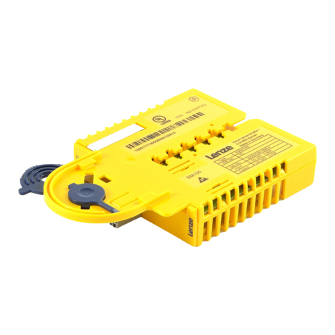
wattstopper LMIO-301 User manual

Installation Instructions
LMIO-301
Digital Lighting Management
Photocell Input Module
Specifications
Voltage ................................................................................................24VDC
Current Consumption ........................................................................... 20mA
Power Supply............................................... WattStopper Room Controllers
Connection to DLM Local Network...........................................2 RJ-45 ports
Analog Input Voltage Range
Input 1 (terminal 9) ....................................................................... 0-5VDC
Input 2 (terminal 10) ................................................................... 1-10VDC
Supply Output @24VDC +/- 15%.............................................................. 5mA
Environment ...................................................................For Indoor Use Only
Operating Temperature.................................... 32° to 104°F (0° to 40°C)
Storage Temperature ......................................23° to 176°F (-5° to 80°C)
Relative Humidity........................................... 5 to 95% (non condensing)
Other:
RoHS compliant
UL2043 Plenum rated
5-year warranty
UNIT DESCRIPTION
The LMIO-301 photocell input module is an accessory for a
networked Digital Lighting Management (DLM) installation
that allows an LMSM segment manager to read ambient
light levels for use in controlling exterior lighting or interior
lighting installed in brightly day-lit spaces such as atriums.
The LMIO-301 works in conjunction with either the LMPO-
200 exterior or LMPS-6000 skylight low voltage photocell
heads.
OPERATION
The LMIO-301 operates on Class 2 power supplied to a DLM
local network by one or more room controllers or an LILM
panel. It transmits light levels over the segment network
as read from one of the remote analog LMPO or LMPS
photocell sensors. The LMIO-301 converts the analog signal
from the photocell sensor to a digital signal that is shared
across the network. The segment manager controls the
lighting based on user-defined setpoints and time delay
settings.
APPLICATION
The LMIO-301 photocell input module is an ideal solution
for any application where exterior lighting needs to be
controlled based on actual ambient exterior light levels
such as parking, site and landscape lighting. Applications
with large expanses of skylight, clearstory or atrium glazing
can also benefit from controlling lighting based on ambient
light entering the building through the glazing.
When controlling outdoor lighting, the LMPO-200 photocell
head mounts on the roof of the building facing North. The
LMPO-200 photocell head is waterproof and has a built in
hood to shield the lens from direct sunlight.
The LMPS-6000 photocell head is designed for indoor
applications with direct exposure to extremely high light
levels as would be present adjacent to the glass in an
atrium, skylight or clearstory.
For full operational details and more features
of the Digital Lighting Management (DLM
System), see the DLM System Installation Guide
available at www.wattstopper.com
INSTALLATION SHALL BE IN
ACCORDANCE WITH ALL
APPLICABLE REGULATIONS,
LOCAL AND NEC CODES.
For Class 2 DLM devices - To be
connected to a Class 2 power source
only.
For Class 2 Device Wiring Only –
Do Not Reclassify and Install as
Class 1, or Power and Lighting
Wiring.
Wire connections shall be rated
suitable for the wire size (lead
and building wiring) employed.
#20 AWG up to 250 feet
#18 AWG up to 1000 feet
Class 2 wiring
LMPO-200
Sensor
Watertight J Box
North
Sensor Hood
To DLM Local Network
LMIO-301
#20 AWG up to 250 feet
Class 2 wiring
LMPS-6000
Sensor
Skylight
Well Vertical
Orientation
Option
To DLM Local Network
LMIO-301
LMPO-200 Outdoor Application
LMPS-6000 Skylight Application
Warranty Information
WattStopper warranties its products to be free of defects in materials and workmanship for a period of five (5) years. There are
no obligations or liabilities on the part of WattStopper for consequential damages arising out of, or in connection with, the use
or performance of this product or other indirect damages with respect to loss of property, revenue or profit, or cost of removal,
installation or reinstallation.
1/2011
13132r3
Please
Recycle
2800 De La Cruz Blvd.
Santa Clara, CA 95050
Phone: 800.879.8585
www.wattstopper.com

TERMINAL CONNECTIONS
1-10V Photocells: connect the photocell
output to terminal 10 (Input 2).
0-5V Photocells: connect the photocell
output to terminal 9 (Input 1)
MOUNTING AND WIRING
Installation shall be in accordance with all applicable
regulations, wiring practices, and codes.
To be connected to a Class 2 power source only. • Class 2
Device Wiring Only – Do Not Reclassify and Install as Class
1, 3 or Power and Lighting Wiring. • Wire connections shall
be rated suitable for the wire size (lead and building wiring)
employed.
The LMIO-301 is UL2043 Plenum rated.
All connections to the LMIO-301 are Class 2 low voltage.
If code requires that the LMIO-301 be mounted in an
enclosure, it can be mounted inside a 4” x 4” junction box,
inside a 21/8” deep (or deeper) 1-gang wall box, in a 3” or 4”
octagonal box, or on a din rail inside a building automation
panel.
Attach the LMRJ Cable
The DLM local network uses free topology low voltage
wiring. The LMIO-301 can connect anywhere on the DLM
local network.
Din rail clip
attached
Removing
din rail clip
Inside a 21/8” deep
single gang
wall box
LMRJ Cables
Occupancy Sensor
Switch
LMPO-200
Outdoor
Photocell
DLM Local Network
Example 1
LMIO-301
Line Voltage
J-Box
0-10 Volt
Ballast
0-10 Volt
Ballast
LMRC-3xx
Room Controller
w/ Network
Bridge
LM-MSTP Wire
LM-MSTP
Wire
Segment Manager
or BACnet BAS
LMRJ Cables
Occupancy Sensor
Switch
LMPO-200
Outdoor
Photocell
Example 2
LMIO-301
Loads
1
2
Line Voltage
LMRC-102
Room
Controller
J-Box
LMBC-300
Network Bridge
Segment Manager
or BACnet BAS
#20 AWG up to 250 feet
#18 AWG up to 1000 feet
Class 2 wiring
Common (Black)
LMPO or LMPS
Photosensor J Box
LMIO-301
457
89
1610
23
+24VDC Input Voltage (Red)
1-10VDC Output Signal (Yellow)
LMIO-301 Terminals
WARNING
TO CONNECT A COMPUTER TO THE DLM LOCAL NETWORK USE THE LMCI100.
NEVER CONNECT THE DLM LOCAL NETWORK TO AN ETHERNET PORT IT
MAY DAMAGE COMPUTERS AND OTHER CONNECTED EQUIPMENT.
RJ45 ports (2)
Configuration
Push button
Blue LEDs (3)
DIP switches (8)
Wiring
Terminals
Configuration
LED (Red)
ADJUSTMENTS
The LMIO-301 is equipped with a Configuration button. This
button is provided for convenience in initiating DLM local
network PnL mode; there are no binding functions needed
for the LMIO-301.
The inputs may be configured using its DIP switches for
different light input levels on each of the photocell input
terminals. Input 1 is claibrated for connection of 0-5VDC
photocells. Input 2 is calibrated for 1-10VDC from photocells
such as WattStopper LMPO and LMPS models.
SWITCHES
1 2
Analog Input 1 (terminal 9)
0-5VDC
Off Off 0 – 200 FC (Default)
On Off 0 – 50 FC
Off On 0 – 500 FC
On On 0 – 6000 FC
SWITCHES
3 4
Analog Input 2 (terminal 10)
1-10VDC
Off Off 0 – 200 FC (Default)
On Off 0 – 50 FC
Off On 0 – 500 FC
On On 0 – 6000 FC
SWITCHES
5, 6, 7
Not Used
SWITCH
8
If you connect, reconnect or
change the photocell while
the LMIO-301 is powered,
toggle DIP switch #8 to On
then Off. This initializes
sampling on the input and
communication with the DLM
Local Network.
LED INDICATORS
The LEDs signify when input 1 or input 2 is activated, when
the 24VDC output is overloaded and when PnL is active.
Blue LEDs
Input 1: Blinks when Data from Input 1 transmits to the
DLM Local Network.
Input 2: Blinks when Data from Input 2 transmits to the
DLM Local Network.
24V Overload: Blinks (1x/sec) when terminal 5 (24VDC)
output exceeds 5mA and the LMIO-301 shuts off the
output. LED goes OFF when the overcurrent condition
is removed.
Red LED
Config: intermittent flashes indicate DLM system local
network activity. Blinking at regular intervals of 2x/
second indicates the local network is in PnL.
TROUBLESHOOTING
The blue LED for 24V Overload is blinking (1x/sec).
This means that the 24VDC output from terminal 5
exceeded 5mA. The output has been shut OFF. The LED
turns OFF when the overcurrent condition is removed.
• Make sure only one photocell is connected to the
LMIO-301.
• Check wiring to terminal 5.
Do not connect
more than one
photocell to the
LMIO-301.

REV DESCRIPTION INT: REV. DATE APPROVED
1 ECO# C03943 PB 7/1/10 CG
2 ECO# C04282 PB 12/29/10 CG
3 ECO# C04633 PB
TITLE BOX PAGE ONLY.
DO NOT MAKE FILM • DO NOT PRINT
MATERIAL: White 16lb (60g/m sq)
Uncoated, recycled stock preferred
Flat Sheet Size: 17” x 11”
Final Trim Size: 8.5” (Wide) x 11” (High)
Ink: CMYK
Print: Two Sides
# Pages: 4
# Sheets: 1
IF YOU HAVE ANY QUESTIONS REGARDING SPECIFICATIONS OR REQUIRE
ADDITIONAL FILE FORMATTING, PLEASE CONTACT Technical Writing Dept.
Phone: 760-804-9701
Email: dawn.revel@wattstopper.com
All information in this drawing is the property of WattStopper
and cannot be copied or used without the written approval of
WattStopper.
Title: LMIO-301 Installation
Instructions
SANTA CLARA, CALIFORNIA
DRAWN BY
PLM
MARCOM
ENGINEERING
QA
TITLE BOX PG
SOWINSKI
SCALE 1:1
Drawing #:
11491
Orig. Drawing Date: 9 JUN 10
Revision Date: 13 JAN 2011
REV. #:
3
Finish2
Fold 4
Fold
3
Fold
2.75”
8.5” 4.25”
4.25”
11”
17”
1
Fold
Other wattstopper Control Unit manuals
Popular Control Unit manuals by other brands
Festo
Festo SPC200-COM-IBS Brief description
Festo
Festo CP-FB11-E Brief description
Wilo
Wilo Wilo-VR-System Installation and operating instructions

NuAire
NuAire NSC1-A-B Series installation manual

Watts
Watts 995 Series Installation, Service, Repair Kits, Maintenance
HORIBA STEC
HORIBA STEC MT-52 Series instructions
