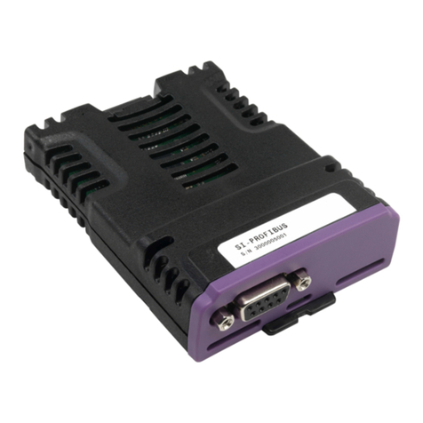
CPU Modules CPU001 and CPU002
October 2005 GFK-1536P
2
New for this Release
1. PID Function Block: An optional filter for the Derivative Term
has been added in version 2.34. This filter improves PID
control loop stability by limiting the contributions of random
variations and step input changes in the Set Point and Process
Variable inputs. For more information, see the last page of this
datasheet.
2. Higher Serial Communications Throughput: Serial
communications throughput can be improved in version 2.34 by
configuring the CPU for Constant Sweep Mode and specifying
a sweep time that is significantly longer than the application’s
Normal Mode sweep time. Ethernet, backplane and serial
communications now share the available time at the end of
constant sweeps.
3. Support for 32-bit register data to the Modbus RTU master
serial protocol. This feature was previously available in
IC200CPUE05 version 2.32. See the document GFK-2220,
Modbus RTU Master Communications, which is available at
www.GEFanuc.com (http://www.gefanuc.com/support/plc/m-
versamax.htm) , for information on using Modbus RTU Master
communications. This document is a supplement to GFK-
0582, the Serial Communications User's Manual.
Product Information
Revision: CPU001-GK, CPU002-EG
Firmware: Version 2.35
Compatibility,
for configuring
or using new
features:
Machine Edition Logic Developer version 2.11 or
later.
VersaPro software version 1.0 or later for
configuration, 1.5 or later to use new features.
Control software version 2.20 or later.
Expansion I/O
Compatibility:
All types of I/O and communications modules
can be used in expansion racks. Some analog
modules require specific module revisions in
expansion racks, as listed below:
Module Module Revision
*ALG320 B or later
*ALG321 B or later
*ALG322 B or later
*ALG430 C or later
*ALG431 C or later
*ALG432 B or later
Resolved for this Release
1. Using repeated port setup COMMREQs to alternate between
SNP slave and Serial I/O protocols will not cause a CPU
Software fault.
2. Setting both ERROR_TERM_SELECT (bit 3) and
DERIVATIVE_ACTION (bit 0) in the Config Word (Address +12
of the Reference Array) no longer reverses the sign of the PID
derivative term.
3. Changing the Integral Rate (Ki) parameter value of a PID
function block from 2 to 1 (that is, from 0.002 to 0.001
Repeats/Sec.) or from 1 to 2 does not cause a step change to
the Integral Term and the Control Variable.
4. When Serial I/O and Hardware Flow Control are specified for
Port 2 in the hardware configuration, transmissions from port 2
will complete properly.
5. Using a Serial Port Setup COMMREQ to switch from one serial
communications protocol to another will not cause a Corrupted
User Memory Fault in the PLC Fault Table
6. Storing a new version of the application program and configuration
using an EZ Program Store device will no longer fail when OEM
protection is enabled.
7. When a serial port is configured for either SNP or SNP-X and a
character with a framing error is received on either serial port, the
port continues responding to received characters.
Operating Notes/Restrictions
1. When a serial port is configured for either Modbus RTU (slave or
master) or Serial I/O, and a parity, framing or over-run error occurs
while a serial message is being received, the next message
received is ignored.
2. When a serial port is configured for Modbus RTU slave, an SNP
master device (for example, a serial programmer or HMI/SCADA
device that uses the SNP protocol) may attach to the port. If the
SNP device is disconnected and then an RTU query is sent to the
port before 10 seconds have elapsed, the port is unable to receive
any serial messages. To recover, power to the CPU must be
turned off and then on.
3. When a serial port is configured for Serial I/O, and a new hardware
configuration is stored that changes the port protocol to SNP, the
port may not respond to SNP Attach messages until the CPU is
powered off and then on.
4. In series 90-30 CPUs, the Shift Register Bit (SHIFR_BIT)
instruction may be used to rotate a bit sequence around a range of
discrete references by specifying the same reference for the output,
Q, and the start reference, ST.
However, in VersaMax CPUs, separate references must be used
for ST and Q, and additional logic must be used to copy the output
bit from the Q reference to the ST reference.
5. When the configured size of a reference table is changed after the
table is stored to flash memory, and the user attempts to read
Initial/Forced Values from flash memory, the table will be filled with
zeros.
6. Using an older revision non-intelligent analog module in an
expansion rack causes a System Configuration Mismatch error to
be logged. The faulted module must be replaced with a newer
revision before it will be scanned. The allowed revisions are
detailed under Compatibility, in the Product Information section,
above.
7. Changing an IND or ISA PID function block integral rate parameter
value from 1 (that is, from 0.001 repeats/sec.) to 0 or from 0 to 1
causes a step change in both the integral term and the control
variable (CV) output. This result is expected. A zero integral rate
value specifies that the integral term contribution to CV is zero,
while a non-zero value specifies a non-zero contribution.
8. If the receiver in a local single rack is powered off while the CPU is
powered on, erroneous ‘Addition of rack’ faults may be logged by
the CPU. It is recommended that both the CPU and the receiver be
powered by a single source.
9. Occasionally, a "Backplane Communication Fault" may be logged
on an intelligent I/O module after power-cycling the main or
expansion rack. This is a diagnostic fault that can be cleared.
10. In very rare instances, when field power is lost on one module, non-
intelligent modules in the same rack may also report faults.
11. In very rare instances, the CPU may not add a module being hot
inserted. It will not generate an ‘Addition of Module’ fault, and the
module will not be scanned. The situation can be corrected by
extracting and re-inserting the module.
12. In very rare instances, a module being hot inserted may cause
analog modules in the same rack to set outputs to zero. In
addition, ‘Loss of Module’, ‘System Configuration Mismatch’, or
field faults may be generated on other modules in the same rack. If
the modules do not return to correct behavior momentarily, power
cycling will restore full operation.
