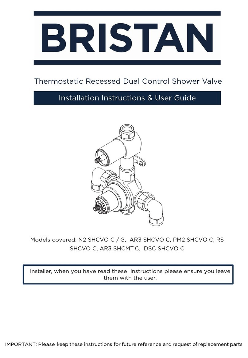
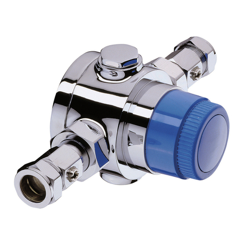
Bristan PM SQSHXDIV C User manual

11
800356/D
Fitting
Instructions
Prism Single Control Surface
Mounted Shower Valve with
Rigid Riser & Diverter to
Handset
Please keep these instructions for future reference
Guarantee & Registration
Guarantee
Registration
All products are manufactured to the highest standards and 5-year guarantee covers any defect in
manufacture.
Any part found to be defective during the above guarantee period will be replaced without charge
providing that the product has been installed in accordance with our instructions, used as intended and
maintained/serviced as recommended.
In the unlikely event that any problems are encountered with this product's performance on installation,
you must obtain guidance/authorisation from our Customer Service Department before any remedial
action is taken and be able to supply proof and date of purchase.
The guarantee excludes damage caused by accident, misuse or neglect and does not cover the
following:
- Those components subject to wear and tear such as 'O' rings and washers etc,
- Damage caused by faulty installation,
- Damage caused by any waterborne debris,
- Damage caused by improper cleaning products,
- Damage caused by the use of non-Bristan parts,
- The product being used for a purpose other than intended.
The company reserves the right, in the event of a claim not covered by the guarantee, to charge the
claimant for parts and labour at current rates. This guarantee is given in addition to and does not affect your
statutory rights.
To register your product with us please complete and return the enclosed registration card.
In the interests of continuous product development we reserve the right to alter the specification as
necessary.
TELEPHONE HELP LINE: 0844 701 6273
PRODUCT CODE: PM SQSHXDIV C
(FI PM SQSHXDIV) (REV.D4) (AJ)
Bristan Limited
Birch Coppice Business Park
Dordon,
Tamworth
Staffordshire
B78 1SG
Web: www.bristan.com
Tel: 0844 701 6274
Fax: 0844 701 6275
Email: enquire@bristan.com
Before starting any installation project please consider:
Prior to drilling into walls, check there are no hidden electrical
wires, cables or water supply pipes with the aid of an
electronic detector. If you use power tools do not forget:
- Wear eye protection
- Unplug equipment after use

110
Fault
No or reduced flow and/or fluctuating
temperature.
Maximum outlet temperature too hot or
too cold.
Maximum temperature too cold or runs
cold after a short time (maximum
temperature set or fully adjusted).
Outlet flow too much.
Only hot or cold water at outlet
Shower will not shut off or leaking from
body.
No thermostatic fail safe.
Fault Finder
Cause
- Shower head blocked.
- Isolating valve partially closed.
- Instantaneous boiler cycling on and off
as flow rate/pressure too low.
- Bottom cap setting incorrect.
- Gravity head of water below minimum
required.
- Blockage in supplies/mixing valve.
- Other draw offs in use causing
pressure or temperature changes.
- Supply pressures unequal.
- Flow limiters incorrectly fitted.
- Air lock in system.
- Shower cross circulating.
- Maximum temperature incorrectly set.
- Hot water is less than 10°C above the
outlet temperature required.
- Insufficient hot water supply or storage
(running out of hot water).
- Instantaneous boiler not igniting as
water flow rate/pressure too low.
- Flow limiters incorrectly fitted.
- Inlet supplies reversed/backwards.
- Inlet supplies blocked.
- Seal damage or wear.
- Scale build up inside mixer.
- Inlet pressures above maximum
recommendations.
- Inlet temperatures not within
specification.
- Piston assembly jammed.
- Thermostat failure.
- Debris trapped in mechanism.
- Inlet supplies reversed.
Rectification
- Clear debris from shower head.
- Open valve.
- Adjust bottom cap setting.
- Check boiler settings are
correct.
- Contact boiler manufacturer.
- Adjust bottom cap setting.
- Raise tank or fit pump.
- Dismantle and check for debris.
- Flush supplies before refitting.
- Do not use other draw offs
whilst showering.
- See maximum pressure
differential in Specifications.
- Check Application Selection.
- Check System Requirements for
correct installation method.
- Check non return valves and
condition of seals.
- Reset maximum temperature.
Refer to Instructions.
- Adjust tank temperature to 60-
65°C. Ensure hot water is up to
temperature.
- Check tank or heater capacities.
Low capacity equals shorter
showering time.
- Adjust bottom cap setting.
- Increase flow through system.
- Increase pressure in system.
- Check for blockages.
- Contact boiler manufacturer.
- Check Application Selection.
- Ensure supplies are connected
correctly to hot and cold inlets.
- Clean out debris.
- Renew all seals.
- Ensure supply pressures are
within Specification.
- Fit pressure regulating valve if
necessary.
- Check inlet temperatures, hot
supply should be 10°C higher
than shower outlet temperature.
- Dismantle and check for
debris.
- Replace thermostat.
- Dismantle and check for debris.
- Ensure supplies are connected
correctly to hot and cold inlets.
- Dismantle and check for debris.
Pressure (bar) 0.1 0.25 0.5 1 2 3
Valve only 8 14.5 26 29 42 52
Full kit * * 4.5 6 9 11
Specifications
General
Temperature Control
Performance
The installation, commissioning and maintenance must be carried out in accordance with
instructions supplied and be installed by qualified and competent persons.
Installations must comply with all Local and National Water Authority Regulations, and Building
and Plumbing Regulations. If in doubt contact a registered plumber or the secretary, Institute of
Plumbing, 64 Station Lane, Hornchurch, Essex, RM21 6NB. Telephone: 01708 472791.
Minimum cold water supply temperature:
Maximum cold water supply temperature:
Maximum hot water supply temperature:
(A temperature of 60-65°C is recommended for ablutionary installations)
A suitable hot water temperature control device should be installed to reduce temperatures
exceeding the above maximum hot water supply temperature.
Minimum temperature differential between hot supply and outlet temperature:
(eg. shower temperature 43°C: minimum hot supply 53°C)
Factory pre-set temperature:
Thermostatic control range:
Operating pressures for valve and kit.
* Operating pressure not recommended, minimum of 0.5 bar (5m head) is required for adequate
performance.
Please note the overhead pressures have been shown for full kit.
5°C
20°C
85°C
Note!
10°C
43°C
38-45°C
Gravity fed system
Instantaneous heated system (Gas or Electric)
Unvented mains pressure system
Pumped system
Isolating valve
Shower inc. non-return valves
Key
Tempering valve
Pressure regulating valve
Strainer
Expansion vessel (optional)
Twin Impeller Pump
Mains pressurised hot water system
System includes:
Expansion vessel
Pressure relief valve
Temperature relief valve
Pressure reducing valve
Energy cut-outs
1 metre
Head
9
Compatible Systems
Cleaning
These finishes should be cleaned using a mild washing up detergent or soap solution, rinsed
with clean water and wiped dry with a soft cloth.
Service Guide
If your thermostatic mixing valve fails to operate it could be the result of incorrect installation.
Please refer to installation and sit requirements. If the valve has operated correctly for a time,
but no longer performs acceptably, it may require servicing/cleaning. Proceed as follows;
1) Isolate hot and cold supplies.
2) Remove the headwork assembly and spline adaptor if applicable
3) For concealed models remove the front plate by inserting a thin blade at
the back of the plate and sliding it around the perimeter. Carefully pull the plate off the valve.
4) Unscrew the cartridge (standard right hand thread).
5) Remove the thermostat, distributor assembly and spring.
6) Remove all visible ‘O’ rings and washers from the body.
30mm spanner required (standard thread).
Ensure that you DO NOT damaged the valve,
pipe work or backplate when undoing the
headwork.
Ensure that you don’t damage
the faces of the piston.
2

Cold Supply
Gravity 0.5 to 1.0 bar
1 to 5 bar
or Pumped
Mains
1.5 to 10 bar
Hot Supply
Gravity 0.5 to 1.0 bar
1 to 5 bar
or Pumped
Gravity 0.1 to 0.2 bar
Gravity 0.2 to 0.5 bar
Gravity above 0.5 bar
Unvented Mains/
Mains Pressurised
Instantaneous
Gas Water Heater
***Instantaneous
Electric Water Heater
Cold
No
Green
(7 litre)
White
Disc
Green
(7 litre)
Green
(7 litre)
Green
(7 litre)
Green
(7 litre)
Hot
No
Yellow
(5 litre)
No
No
Yellow
(5 litre)
*Yellow
(5 litre)
No
Comments
Maximum pressure
loss ratio 5:1
# Use arrangement
for pumped system
**Open Bottom Cap extra
½ turn anti-clockwise
**Open Bottom Cap extra
½ turn anti-clockwise
Supply System Flow Limiter
# Limiters can be fitted if water economy is required.
* Yellow (5 litre) limiter may not be necessary on some gas heaters.
** The bottom cap is factory set at 3/4 turn from fully closed position.
*** - It is a requirement of Instantaneous Electric Water Heaters that a stable flow of water
passes through the heater. This requirement can be satisfied by using a flow stabiliser (960060) fitted
prior to the heater and should be adjusted to give a temperature of between 45-50°C from the heater.
IMPORTANT!
Fitting limiter or orifice disc and Bottom Cap adjustment
Remove wall bracket from mixing valve (see Installation). Peel off label to reveal bottom cap,
with a marker pen, mark a point in-line with slot. Turn extra anticlockwise ½ (180°) turn using
a screw driver.
Mark
Point
Washer
Inlet elbow
Retaining
ring
Limiter or
orifice disc
Green - 7 litre
Yellow - 5 litre
White orifice disc
3
Compatible Systems
For optimum performance from the thermostatic mixing valve, see the table below for
recommendations for flow limiter selection.
8
Maximum Temperature Setting
The maximum mixed water temperature should be limited to ensure no undesirable
temperature is obtained. If necessary adjust as follows -
1) Turn the knob anti-clockwise to the maximum temperature position.
2) Unscrew lever and remove grub screw using hexagonal key.
3) Pull off knob to reveal spindle.
4) Using a fine screwdriver through the spindle, turn the adjusting screw to alter the
maximum temperature.
5) When the desired temperature is obtained replace the knob assembly.
Turn the adjusting screw clockwise for cooler temperature.
Turn the adjusting screw anti-clockwise for warmer temperature.
>
>
Increase
Temperature
Decrease
Temperature

74
Installation
The installation, commissioning and maintenance must be carried out in accordance with
instructions supplied and be installed by qualified and competent persons. Installations
must comply with all Local and National Water Authority Regulations, and Building and
Plumbing Regulations.
1. Determine the routes of the hot and cold supply pipework. The mixer can be fed from
the top, rear or bottom. See dimensions below for pipe inlet centres.
Ensure valve and rigid riser will fit without fouling the ceiling.
2. Install supply pipework. Accessible isolating valves are recommended for
maintenance.
Try fit of mixing valve to pipework, each inlet elbow can be unscrewed 1½ turns to
allow for adjustment and location.
3. Remove the wall bracket from the rear of the mixer by loosening retaining grubscrew
on the underside of mixer with the hexagon key.
4. Use the wall bracket to mark hole positions. Drill wall and insert suitable wall plugs for
fixing screws.
5. Fit bracket to wall using fixing screws. Ensure retaining hole for grubscrew is at the
bottom.
Ensure supply pipework is flushed to clear debris before connecting mixer. Do
not use sealing compounds on connections.
6. Offer mixing valve to pipework and tighten the wall bracket retaining screw.
Exposed Model (see fig.1, page 6)
Note!
Note!
Important!
Installation
Using complete valve and kit (see fig.1 on previous page)
Note -
Note -
1) With the shower mixing valve installed, connect the rigid riser (with brackets and slider) onto
the valve using the extension tube. Ensure all seals are correct.
Prior to drilling the wall for the wall brackets ensure adequate movement can be achieved
from the handset holder.
2) Use the brackets as a guide for the wall connection. Mark/ drill and plug holes to suit wall
brackets and fix into place using fittings. Secure into place by screwing the rod into the rail
and tightening the grub screw, using hexagonal key. See below.
The rod (see Wall Bracket Assembly) may both need to be cut to size in certain
installations.
3) Screw on the shower rose/ hose and handset using the washers supplied.
Lever orientation is for reference only.
Grubscrew

5
Valve Assembly
Exploded diagram showing valve components and their spare kits codes.
6
REF
NUMBER DECRIPTION PART
NUMBER
1
2
3COMPLETE ELBOW ASSEMBLY SKINLET-7
4WALL COVER PLATE 220039
DRAWING SHOWN WITHOUT
HANDLE ASSEMBLY
BACKPLATE EXP - 220019
COMPLETE CARTRIDGE ASSEMBLY SKAK4000
3
4
2
1
Please note all diagrams are for reference only and may differ in appearance of purchased product.
Fig. 1
SHOWER ROSE
WASHER
WALL BRACKET
ROD & RING
SHOWER HOSE
WASHER
HANDSET
WASHER
DIVERTER
WASHER
EXTENSION PIECE
SHOWER VALVE
HANDSET HOLDER
Table of contents
Other Bristan Control Unit manuals

Bristan
Bristan N2 SHCDIV G Mounting instructions

Bristan
Bristan OP TS1503 CL C Mounting instructions

Bristan
Bristan OP TS1503 EL C Mounting instructions

Bristan
Bristan MT753CP Mounting instructions

Bristan
Bristan TS6000ECP Mounting instructions

Bristan
Bristan MT503CP Mounting instructions

Bristan
Bristan MT503CP Mounting instructions

Bristan
Bristan Opac TS1503 Mounting instructions

Bristan
Bristan TS4753ECP Mounting instructions

Bristan
Bristan N2 SHCVO C Wiring diagram