manuals.online logo
Brands
  1. Home
  2. •
  3. Brands
  4. •
  5. wattstopper
  6. •
  7. Security Sensor
  8. •
  9. wattstopper Legrand LMPX-100 User manual

wattstopper Legrand LMPX-100 User manual

SENSOR PLACEMENT
Sensor
Ceiling
COVERAGE PATTERN
Coverages shown are maximum and represent
half-step walking motion.
Side view
10’
Top view
40’
0 7’ 15’ 25’ 45’
45’
Quick Start Guide
LMPX-100
Digital Lighting Management
PIR Corner Mount
Occupancy Sensor
Dense Lens
Line
Voltage
Room
Controller
J-Boxes
Daylight Sensor
SwitchSwitch
Corner Mount
Sensor
Ceiling Mount
Sensor
DLM Local Network
Low Voltage
LMRJ Cables
Loads
2
1
Line/Hot
Black wire
Neutral
White wire
Red wire
to Load A (1)
Yellow wire
to Load B (2)
LMRC
102
Room
Controller
J Box
Corner Mount
Occupancy
Sensor
Switch
To
Load/Line
(Class 1 wiring)
DLM Local Network
(low voltage, Class 2)
LMRJ Cables
CONNECTIVITY
The illustrations below show examples of free-topology wiring. The LMPX-100
communicates to all other Digital Lighting Management devices connected to the low
voltage DLM Local Network, regardless of their position on the DLM Local Network.
Sensor
30'
30'
Voltage: ...............................................................................24VDC
Current Consumption:........................................................... 7mA
Power Supply:............. Watt Stopper/Legrand Room Controllers
Connection to the DLM Local Network.......................RJ-45 plug
DLM Local Network Characteristics:
Provides low voltage power over Cat 5e cable (LMRJ).
Supports up to 24 communicating devices, including 4
LMRC-10x or LMPL-101 max per each DLM Local Network.
Free topology up to 1,000ft of low voltage cable.
Environment ................................................. For Indoor Use Only
Operating Temperature ....................32° to 131°F (0° to 55°C)
Storage Temperature...................... 23° to 176°F (-5° to 80°C)
Relative Humidity...........................5 to 95% (non condensing)
Patent Pending
THIS UNIT IS PRESET FOR PLUG n’ GO™
OPERATION, ADJUSTMENT IS OPTIONAL.
For full operational details, adjustment and more
features of the product, see the DLM System
Installation Guide provided with the LMRC-102 and
also available at www.wattstopper.com
INSTALLATION SHALL BE
IN ACCORDANCE WITH ALL
APPLICABLE REGULATIONS,
LOCAL AND NEC CODES.
Intended for Listed Class
2 DLM Devices.
For Class 2 DLM devices -
To be connected to a Class
2 power source only.
For Class 2 Device Wiring Only –
Do Not Reclassify and Install as
Class 1, or Power and Lighting
Wiring.
Wire connections shall be rated
suitable for the wire size (lead and
building wiring) employed.
6/2009
11440r1
Please
Recycle
2800 De La Cruz Blvd.
Santa Clara, CA 95050
Phone: 800.879.8585
www.wattstopper.com
FACTORY PRESET OPERATION
Sensor Parameters
T-DELAY Time Delay 20 minutes
Passive Infrared
Sensitivty 90%
W-T Walk Through OFF
TROUBLESHOOTING
Loads do not operate as expected.
LEDs don’t light, display
is off
1. Check to see that the the sensor is connected to the DLM local Network.
2. Check for 24VDC input to the sensor: Plug in a different DLM device at the sensor location.
If the device does not power up, 24VDC is not present.
• Check the high voltage connections to the room controller.
• If high voltage connections are good and high voltage is present, recheck DLM local
Network connections between the sensor and the room controller.
The wrong lights are
controlled
1. Configure the sensor to control the desired lights using the Push n’ Learn adjustment
procedure.
LEDs turn ON and OFF but
load doesn’t switch
1. Make sure device is not in PnL.
2. Check load connections to room controller.
WARNING: TO CONNECT A COMPUTER TO THE DLM LOCAL NETWORK USE THE
LMCI100. NEVER CONNECT THE DLM LOCAL NETWORK TO AN ETHERNET PORT
 DOING SO MAY DAMAGE COMPUTERS AND OTHER CONNECTED EQUIPMENT.
Load 1 Loads 2-8
or more**
Plug Load
ON Mode
Operation* AUTO-ON
MANUAL-ON
if switch is
used.
AUTO-ON
if switch is
not used.
AUTO-ON
Blink Warning OFF OFF OFF
Daylighting ON OFF OFF
*Auto-OFF is enabled according to the sensor Time Delay when a
sensor is bound to the load, regardless of whether the load was turned
on automatically with occupancy or manually using a switch.
** Max 8 loads using LMRC-100 series room controllers.
Mounting plate
back view
European
3.5”
Octagon
4” Octagon
4” Square
2 Gang2 Gang 1 Gang
European
3.5”
Octagon
4” Octagon
4” Square
2 Gang2 Gang 1 Gang
Using a screwdriver, punch out the
holes for the corresponding junction box.
J-box
Wall
Mounting plate
and base
LMRJ-C8 coupler
(included, LMRJ-S8 splitter optional)
Occupancy
Sensor
Snug
Ring
Wall
Snug
Ring
Secure
Snug
Ring
Loose
Screw
through
wall
MOUNTING
Mounting plate
Ceiling
Hole
0.825”
(20.9mm) dia.
Stem
Base Swivel bracket
Occupancy
Sensor
Ceiling
Mounting plate
Snug
Ring
Loose
Snug
Ring
Secure
Snug
Ring
LMRJ-C8 coupler
(included, LMRJ-S8
splitter optional)
WARNING: Do Not Install To Cover a Junction Box Having Class 1, 3 or Power and Lighting Circuits.
through
ceiling tile
Load
Parameters

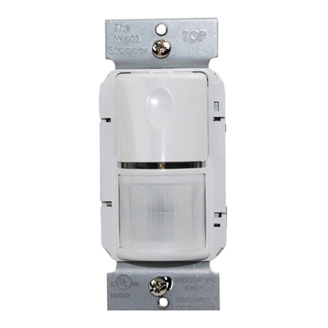
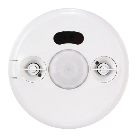
Other wattstopper Security Sensor manuals

wattstopper CI-300 User manual

wattstopper

wattstopper CI-300 User manual

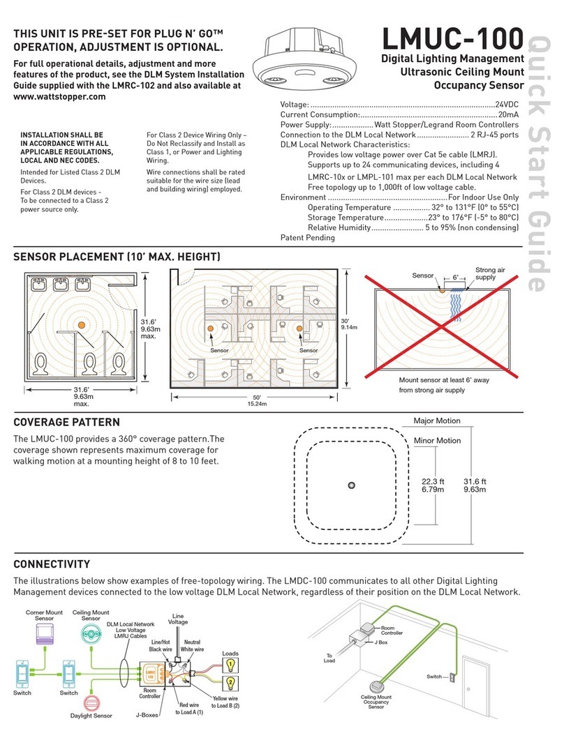
wattstopper LMUC-100 User manual

wattstopper

wattstopper LMUC-100 User manual

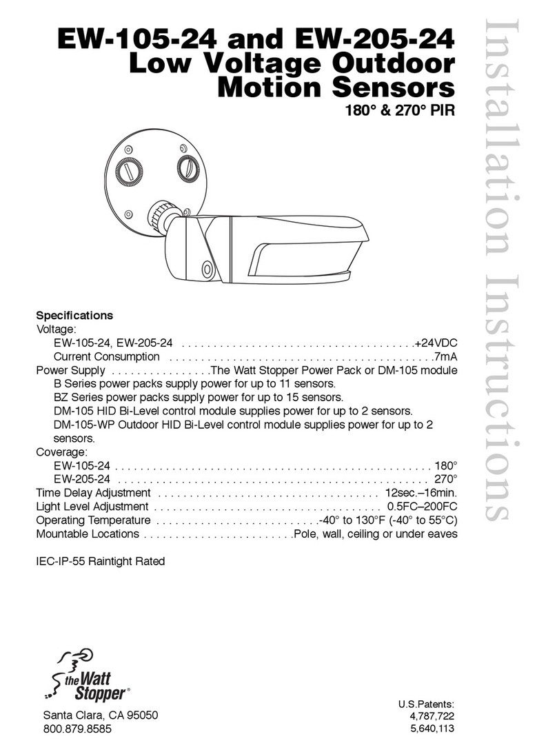
wattstopper EW-105-24 User manual

wattstopper

wattstopper EW-105-24 User manual

wattstopper Legrand LMPX-100-1 User manual

wattstopper

wattstopper Legrand LMPX-100-1 User manual

wattstopper CX-105 User manual

wattstopper

wattstopper CX-105 User manual

wattstopper LMDW-101 User manual

wattstopper

wattstopper LMDW-101 User manual

wattstopper LMDC-100 User manual

wattstopper

wattstopper LMDC-100 User manual

wattstopper WS-250 User manual

wattstopper

wattstopper WS-250 User manual

Popular Security Sensor manuals by other brands

Xtralis VESDA VLI installation instructions

Xtralis

Xtralis VESDA VLI installation instructions

Elko iNELS RFWD-100 manual

Elko

Elko iNELS RFWD-100 manual

Hilti PS 200 S manual

Hilti

Hilti PS 200 S manual

Velleman PIR600 user manual

Velleman

Velleman PIR600 user manual

Honeywell IS-215T installation instructions

Honeywell

Honeywell IS-215T installation instructions

Panasonic 4318 Technical description

Panasonic

Panasonic 4318 Technical description

PCB Piezotronics TORKDISC 5302D-03A Installation and operating manual

PCB Piezotronics

PCB Piezotronics TORKDISC 5302D-03A Installation and operating manual

EVERSPRING EVRESP816 manual

EVERSPRING

EVERSPRING EVRESP816 manual

Emerson MRLDS-250 Quick setup guide

Emerson

Emerson MRLDS-250 Quick setup guide

Det-Tronics X Series Addendum

Det-Tronics

Det-Tronics X Series Addendum

Agilent Technologies 8355 Sulfur user manual

Agilent Technologies

Agilent Technologies 8355 Sulfur user manual

AJAX MotionProtect user manual

AJAX

AJAX MotionProtect user manual

MSA FlameGard 5 UV/IR Communications manual

MSA

MSA FlameGard 5 UV/IR Communications manual

Omron F3SP-U4P-TGR user manual

Omron

Omron F3SP-U4P-TGR user manual

Texecom Premier Elite AM 360DT installation manual

Texecom

Texecom Premier Elite AM 360DT installation manual

escofred SLD-300 owner's manual

escofred

escofred SLD-300 owner's manual

AMC SMILE 19 quick start guide

AMC

AMC SMILE 19 quick start guide

Vision ZP 3102 EU Installation & operation manual

Vision

Vision ZP 3102 EU Installation & operation manual

manuals.online logo
manuals.online logoBrands
  • About & Mission
  • Contact us
  • Privacy Policy
  • Terms and Conditions

Copyright 2025 Manuals.Online. All Rights Reserved.