wattstopper FSIR-100 User manual

User Guide
FSIR‑100
Wireless IR Configuration Tool
Patents Pending
Operation ................................. 2
Batteries .................................. 3
Navigation ................................ 4
Home Menu.............................. 5
Screens .................................... 6
Troubleshooting..................... 27
CONTENTS
The FSIR-100 Wireless IR Configuration Tool is
a handheld tool for setup and testing of Watt-
Stopper fixture sensors and provides wireless
access for setup and parameter changes.
The FSIR-100 display shows menus and
prompts to lead you through each process.
The navigation pad provides a familiar way to
navigate through the customization fields.
Within a certain mounting height of the sensor,
the FSIR-100 allows modification of the system
without requiring ladders or tools; simply with
a touch of a few buttons. Products available for
use with the FSIR-100 are shown on the Home
Menu.

2
Operation
The FSIR-100 IR transceiver allows bi-
directional communication between the
sensor and the FSIR-100 configuration
tool . Simple menu screens let you see the
current status of the system and make
changes. It can change sensor parameters
such as high/low mode, sensitivity, time
delay, cut off, setpoints and more.
Range
Indoor: 1 - 30’
Outdoor: 1 - 15’
3
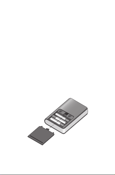
Batteries
The FSIR-100 operates on three standard
1.5V AAA Alkaline batteries
or three rechargeable AAA NiMH batteries.
The battery status displays in the upper right
corner of the display. Three bars next to BAT=
indicates a full battery charge. A warning
appears on the display when the battery level
falls below a minimum acceptable level. To
conserve battery power, the FSIR-100 auto-
matically shuts off 10 minutes after the last
key press.

4
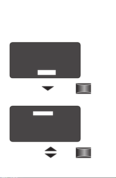
Navigation
You navigate from one field to another using
(up) or (down) arrow keys. The active field is
indicated by flashing (alternates between yel-
low text on black background and black text
on yellow background).
Once active, use the Select button to move to
a menu or function within the active field.
Value fields are used to adjust parameter
settings. They are shown in “less-than/
greater-than” symbols: <value>. Once active,
change them using (left) and (right) arrow
keys. In general the up key increments and
the down key decrements a value. Selections
wrap-around if you continue to press the
key beyond maximum or minimum values.
Moving away from the value field overwrites
the original value. The Home button takes
you to the main menu. The Back button can
be thought of as an undo function. It takes
you back one screen. Changes that were in
process prior to pressing the key are lost.
5
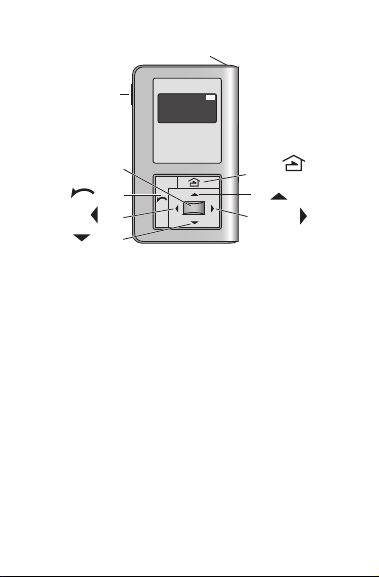
Home/
Main Menu
Up
Select
Down
Right/Next
Left
Back
Power
On/Off
IR Window
BAT=
Home Menu
The Home (or Main) menu displays after
the powerup process completes. It contains
information on the battery status and six
menu choices. Press up/down buttons to lo-
cate the desired function then press Select.
The following menus are applicable for the
FSP-211.

6
HOME MENU
The Home (or Main) menu displays after the
power-up process completes. It contains
information on the battery status and it
shows the available sensor options. Press the
up or down buttons to highlight the desired
sensor then press Select.
FSP-211
=
BAT
Press
Select
Choose
FSP-211

7
NEW SETTINGS
New Settings allow you to select the same
display as shown on page 8 such as: High/
Low Mode, Time Delay, Cut Off, Sensitivity,
Setpoint and Ramp/Fade rates.
Press
Select
New Settings
Current Settings
Test Mode
Recall Profiles
Sensor Configuration
FSP-211

8
High Mode
When the sensor detects motion the dimming
control output ramps up to the selected HIGH
light level (default is 10V).
Range: 0 V to 10 V
Increments: 0.2 V
High Mode:
Low Mode:
Time Delay:
Cut Off:
Sensitivity:
Setpoint:
NEXT SEND
<10 Volts>
<1 Volts>
<5 Min>
<1 hour>
<Max>
<4 fc>
FSP-211 Settings
Press the Left/Right Arrow
to Increase or Decrease Volts

9
Low Mode
After the sensor stops detecting motion and
the time delay expires the dimming control
output fades down to the selected LOW light
level (default is 1V). Low Mode will usually be
less than High Mode for proper functioning.
Range: OFF, 0 V to 9.8 V
Increments: 0.2 V
High Mode:
Low Mode:
Time Delay:
Cut Off:
Sensitivity:
Setpoint:
NEXT SEND
<10 Volts>
<1 Volts>
<5 Min>
<1 hour>
<Max>
<4 fc>
FSP-211 Settings
Press the Left/Right Arrow
to Increase or Decrease Volts

10
Time Delay
The time period that must elapse after the
last time the sensor detects motion for the
lights to fade to LOW mode (default is 5
minutes).
Range: 30 sec, and 5 min to 30 min
Increments: 1 min
High Mode:
Low Mode:
Time Delay:
Cut Off:
Sensitivity:
Setpoint:
NEXT SEND
<10 Volts>
<1 Volts>
<5 Min>
<1 hour>
<Max>
<4 fc>
FSP-211 Settings
Press the Left/Right Arrow
to Raise or Lower Time Delay

11
Cut Off
The time period that must elapse after the
lights fade to LOW mode and the sensor
detects no motion for the lights to turn OFF
(default is 1 hour).
Range: None (No cut off, lights will stay in low
mode) 1 min to 59 min, 1 hr to 5 hr (press and
hold should cause to move faster through the
increments)
Increments: 1 min or 1 hr
High Mode:
Low Mode:
Time Delay:
Cut Off:
Sensitivity:
Setpoint:
NEXT SEND
<10 Volts>
<1 Volts>
<5 Min>
<1 hour>
<Max>
<4 fc>
FSP-211 Settings
Press the Left/Right Arrow to
Increase or Decrease Cut Off

12
Sensitivity
Sensitivity is the response of the PIR detector
to motion within the sensor’s coverage area
(default is max).
Range: On-Fix, Off-Fix, Low, Med, Max
Sequence: On-Fix, Off-Fix, Low to Max
(On-Fix, relay closed, occupancy detection
disabled; Off-Fix, relay open, occupancy
detection disabled)
High Mode:
Low Mode:
Time Delay:
Cut Off:
Sensitivity:
Setpoint:
NEXT SEND
<10 Volts>
<1 Volts>
<5 Min>
<1 hour>
<Max>
<4 fc>
FSP-211 Settings
Press the Left/Right Arrow
to Increase or Decrease
Sensitivity

13
Setpoint
Setpoint is the selectable ambient light level
threshold that will hold the lights off or at
LOW level when the sensor detects motion
(default is 4 fc).
Range: Auto, None, 1 fc to 250 fc
Increments: 1 fc (press and hold should
cause to move faster thru the increments)
Sequence: Auto, None, 1 fc to 250 fc (None
will disable the setpoint feature)
The Auto option invokes an automatic calibra-
tion procedure to establish an appropriate
setpoint based upon the contribution of the
electric light. As part of this procedure, the
High Mode:
Low Mode:
Time Delay:
Cut Off:
Sensitivity:
Setpoint:
NEXT SEND
<10 Volts>
<1 Volts>
<5 Min>
<1 hour>
<Max>
<4 fc>
FSP-211 Settings
Press the Left/Right Arrow
to Increase or Decrease
Setpoint

14
controlled load is turned on for two minutes
to warm up the lamp, and then switched
off and on eight times, terminating in an off
state. After this process, a new setpoint value
is automatically calculated.
Next
To view more settings go to NEXT and press
the Select button.
High Mode:
Low Mode:
Time Delay:
Cut Off:
Sensitivity:
Setpoint:
NEXT SEND
<10 Volts>
<1 Volts>
<30 Sec>
<1 hour>
<Max>
<4 fc>
FSP-211 Settings
Choose NEXT to View
More Settings

15
Ramp Up
Time period for light level to increase from
LOW to HIGH (default is none; lights switch
instantly).
Range: None, 1 sec to 60 sec
Increments: 1 sec
Ramp Up:
Fade Down:
PRIOR SAVE SEND
<none>
<none>
FSP-211 Settings
Press the Left/Right Arrow to
Increase or Decrease Sec

16
Fade Down
Time period for light level to decrease from
HIGH to LOW (default is none; lights switch
instantly).
Range: None, 1 sec to 60 sec
Increments: 1 sec
Prior
Ramp Up:
Fade Down:
PRIOR SAVE SEND
<none>
<none>
FSP-211 Settings
Press the Left/Right Arrow to
Increase or Decrease Sec
Ramp Up:
Fade Down:
PRIOR SAVE SEND
<1 sec>
<1 sec>
FSP-211 Settings
Press the
Down Arrow
to Choose PRIOR
Press
Select
17
To go back to previous settings go to PRIOR
and press the Select button.
Save
Ramp Up:
Fade Down:
PRIOR SAVE DONE
<1 sec>
<1 sec>
FSP-211 Settings
Press the
Down Arrow
to Choose SAVE
Profile 1
Profile 2
Profile 3
Profile 4
Profile 5
Profile 6
Cancel
Save FSP-211 Parms
Press
Select
Press
Select
Press the
Up/Down Arrow
to Choose Profile
Save FSP-211 Parms

18
Caution: SAVE must be selected in order
for the settings to be stored. To Save these
parameters as one of the profiles go to SAVE
and press the Select button.
Send
To program the FSP-211 with the selected
parameters go to SEND and press the Select
button. The controlled load should cycle on/
off once the sensor is programmed.
Ramp Up:
Fade Down:
PRIOR SAVE SEND
<1 sec>
<1 sec>
FSP-211 Settings
Press the Down Arrow
to Choose SEND

19
CURRENT SETTINGS
Current Settings allow you to recall the
parameters for a specific sensor. These are
read only parameters.
Point and
Press Select
Point to desired
Occupancy Sensor
Press ‘Select’
New Settings
Current Settings
Test Mode
Recall Profiles
Sensor Configuration
FSP-211
Press
Select
Choose
Current
Settings

20
View Current Settings
Press Select to view more settings.
To go back to previous settings go to PRIOR
and press the Select button.
Light Level
<10 Volts>
<1 Volts>
<0.5 Min>
<1 hour>
<Max>
<4 fc>
FSP-211 Settings
High Mode:
Low Mode:
Time Delay:
Cut Off:
Sensitivity:
Set Point:
NEXT DONE
Press Select to
View More Settings
Ramp Up:
Fade Down:
Light Level:
PRIOR SAVE DONE
1 sec
1 sec
15fc
FSP-211 Settings
Press the Down Arrow
to Choose PRIOR
Table of contents
Other wattstopper Tools manuals


