Tyco Electronics 549043-1 User manual

Page 1 / 17 ECOC: EGC0 ; LOC: AI
Betriebsanleitung
Pistol Grip
für Feinstlackdraht
PN 549043-1
412-18911 / 8-744013-1
20.05.2008, MD, Rev.A
Operating instructions
Pistol Grip
for magnet wire
PN 549043-1

Page 2 / 17 ECOC: EGC0 ; LOC: AI
PN 8-744013-1 412-18911 Rev.A
1 Deutsch............................................................................................................................. 3
2 English............................................................................................................................11

Page 3 / 17 ECOC: EGC0 ; LOC: AI
PN 8-744013-1 412-18911 Rev.A
Inhaltsverzeichnis
1 Umgang mit der Betriebsanleitung .................................................................................4
2 Grundlegende Sicherheitshinweise................................................................................4
2.1 Zuständigkeit.................................................................................................................... 5
2.2 Hinweise zum Einrichten und Betreiben des Werkzeugs..............................................6
2.3 Hinweise zum Warten und Instandhalten des Werkzeugs.............................................5
3 Verwendungszweck ......................................................................................................... 5
4 Technische Daten............................................................................................................. 6
5 Vorbereitung..................................................................................................................... 6
6 Bedienen........................................................................................................................... 7
7 Verschleißteilwechsel ...................................................................................................... 9
8 Wartung...........................................................................................................................10

Page 4 / 17 ECOC: EGC0 ; LOC: AI
PN 8-744013-1 412-18911 Rev.A
1 Umgang mit der Betriebsanleitung
Die Betriebsanleitung muss ständig an dem Werkzeug verfügbar sein.
Jeder, der mit Arbeiten an dem Werkzeug beauftragt ist, muss die Betriebsanleitung kennen und
beachten.
Die Firma Tyco Electronics lehnt jede Haftung für Schäden ab, der durch Nichtbeachten von Hinweisen
an dem Werkzeug oder in der Betriebsanleitung entsteht.
Die Betriebsanleitung ist vom Benutzer des Werkzeugs um Anweisungen aufgrund bestehender
nationaler Vorschriften zur Unfallverhütung und zum Umweltschutz zu ergänzen.
2 Grundlegende Sicherheitshinweise
Das Werkzeug ist nach dem Stand der Technik und den anerkannten sicherheitstechnischen Regeln
gebaut.
Beim Ausführen von Arbeiten, wie Aufstellen, in Betrieb nehmen, Einrichten, Betreiben, Ändern der
Einsatzbedingungen und Betriebsweisen, Warten und Instandhalten des Werkzeugs, sind die in der
Betriebsanleitung vorgeschriebenen Ausschaltprozeduren zu beachten.
RoHS Information
Informationen über das Vorkommen und Standort jeglicher Substanzen die den RoHS-Richtlinien
(Restriction on Hazardous Substances) unterliegen sind auf der folgenden Website zu finden:
http://www.tycoelectronics.com/customersupport/rohssupportcenter/
Dort „Find Compliance Status…“ anwählen und die entsprechenden Teile-Nummern eingegeben.
2.1 Zuständigkeit
Das Werkzeug darf nur von ausgebildetem und autorisiertem Personal betrieben werden. Die
Zuständigkeit des Personals für Bedienen, Rüsten, Warten und Instandhalten ist vom Benutzer des
Werkzeugs klar festzulegen und einzuhalten. Insbesondere ist die Zuständigkeit für Arbeiten an der
elektrischen und pneumatischen Ausrüstung festzulegen. Solche Arbeiten bleiben nur ausgebildeten
Fachleuten vorbehalten.
Eigenmächtige Veränderungen an dem Werkzeug schließen eine Haftung des Herstellers bzw. Lieferers
für daraus resultierende Schäden aus.
2.2 Hinweise zum Einrichten und Betreiben des Werkzeugs
Das Werkzeug darf nur in technisch einwandfreiem Zustand sowie sicherheits- und gefahrenbewusst
eingerichtet und betrieben werden.
Vor jeder Inbetriebnahme ist zu prüfen, ob alle Sicherheitsvorrichtungen, insbesondere Schutz-
abdeckungen, angebracht sind und einwandfrei funktionieren.
Schutzabdeckungen dürfen nur bei Stillstand und elektrisch ausgeschaltetem Werkzeug entfernt werden.
Insbesondere Gehäuse und Abdeckungen dürfen nur von fachkundigem Personal entfernt werden.
Achtung:
Beim Berühren von Stromführenden Teilen besteht Lebensgefahr!
Page 5 / 17 ECOC: EGC0 ; LOC: AI
PN 8-744013-1 412-18911 Rev.A
Wenn anzunehmen ist, dass sich das Werkzeug nicht mehr gefahrlos betreiben lässt, ist es außer Betrieb
zu setzen und gegen unbeabsichtigtes Einschalten zu sichern.
Das Werkzeug ist ausschließlich für den in der Betriebsanleitung beschriebenen Zweck zu verwenden.
Für Schäden, die aus nicht bestimmungsgemäßer Verwendung entstehen, haftet der Hersteller bzw.
Lieferer nicht: das Risiko hierfür trägt allein der Benutzer.
2.3 Hinweise zum Warten und Instandhalten des Werkzeugs
Werkzeug- und Anlagenteile, an denen Wartungs- und Instandsetzungsarbeiten durchgeführt werden,
müssen, falls in der Betriebsanleitung nichts Gegenteiliges erwähnt ist, unbedingt von der Spannungs-
zufuhr getrennt werden.
Die frei geschalteten Teile müssen zuerst auf Spannungsfreiheit geprüft, dann geerdet und kurz-
geschlossen, sowie benachbarte, unter Spannung stehende Teile isoliert werden.
Die elektrische Ausrüstung des Werkzeugs ist regelmäßig zu prüfen. Mängel, wie z.B. lose Verbindungen
oder angeschmorte Kabel, sind unverzüglich zu beseitigen.
Sind Arbeiten an Spannungsführenden Teilen notwendig, ist eine zweite Person hinzuzuziehen, die im
Notfall je nach Notwendigkeit den Notaus- bzw. Hauptschalter betätigt oder die Spannungszufuhr zum
Werkzeug unterbricht. Es ist ausschließlich spannungsisoliertes Werkzeug zu benutzen!
3 Verwendungszweck
Die Pistol-Grip mit der PN 549043-1 dient zum Verarbeiten von Feinstlackdrahtverbinder. Die
verschiedenen Varianten der folgenden Basis-Nummern sind zu verwenden:
Buchse PN 964320 Stift PN 964318
Abbildung 1 Abbildung 2

Page 6 / 17 ECOC: EGC0 ; LOC: AI
PN 8-744013-1 412-18911 Rev.A
Funktionsprinzip:
Abbildung 3
Hinweis:
Das Werkzeug ist ausschließlich für den beschriebenen Zweck zu verwenden!
4 Technische Daten
Abmessungen: ca. 157mm x30mm x121mm [LxBxH]
Gewicht: 0,335kg
Elektrische Anschlüsse: -
Pneumatische Anschlüsse: -
Schalldruckpegel: -
Transport: im Plastikkoffer
5 Vorbereitung
Das Empfohlene Einpressmaß X liegt zwischen 4,6mm bis 4,9mm. Das genaue Maß muss durch
Testkontaktierung ermittelt werden. Das Abstandsmaß 8,5mm kann nach Lösen der 6 Kt.- Mutter (Pos.
43) eingestellt werden. Zum Einstellen wird die Aufnahmemutter (Pos. 22) von Hand gedreht. Eine 90°-
Drehung entspricht einer axialen Verstellung von 0,125mm. Das Drehen der Aufnahmemutter (Pos. 22)
gegen den Uhrzeigersinn vergrößert das Abstandsmaß, Drehen im Uhrzeigersinn verringert das Maß.
Nach dem Einstellen immer die 6 Kt.- Mutter (Pos. 43) wieder anziehen (siehe Abbildung 4).

Page 7 / 17 ECOC: EGC0 ; LOC: AI
PN 8-744013-1 412-18911 Rev.A
Abbildung 4
6 Bedienen
1. Die Pistol-Grip Handzange muss in Grundstellung stehen. Der Stift mit der Nummer 964318 muss
bündig in die Aufnahmemutter eingelegt werden. Anschließend wird die Buchse fixiert (siehe Abbildung
5).
Abbildung 5
2. Die Buchse mit der Nummer 964320 muss zwischen den Federn eingelegt werden (siehe Abbildung
6). Es ist darauf zu achten, dass die Buchse bündig anliegt und zwischen den Federn klemmt.
Anschließend muss der Lackdraht in die Buchse eingeschoben werden. Der Lackdraht muss auf der
Einpressseite überstehen. Der Überstehende Lackdraht wird beim Einpressen des Stiftes mit der
Nummer 964318 abgetrennt. Während des Einpressens des Stiftes muss der Lackdraht mit der Hand
fixiert werden.

Page 8 / 17 ECOC: EGC0 ; LOC: AI
PN 8-744013-1 412-18911 Rev.A
Abbildung 6
3. Die Zange muss über den voreingestellten Hub (siehe Kapitel Vorbereitung) gedrückt werden, bis die
Ratsche wieder selbstständig in Grundstellung übergeht.
Das Funktionsprinzip der Zange ist auch im Kapitel Verwendungszweck näher erläutert.
Abbildung 7

Page 9 / 17 ECOC: EGC0 ; LOC: AI
PN 8-744013-1 412-18911 Rev.A
7 Verschleißteilwechsel
Um die Verschleißteile (Pos.32) Federn zu wechseln, muss die Mutter (Pos.34) gelöst werden.
Anschließend die Zylinderschraube (Pos.33) durch Herausziehen entnehmen (siehe Abbildung 8). Die
Federn sind immer paarweise zu wechseln.
Der Einbau erfolgt in umgekehrter Reihenfolge.
Es ist darauf zu achten, dass die Federn richtig eingesetzt werden!
Abbildung 8
Um die in Abbildung 9 aufgeführten Verschleißteile zu wechseln, muss zunächst die 6 Kt.- Mutter
(Pos.43) mit einem Gabelschlüssel SW8 gelöst werden. Anschließend kann die Aufnahmemutter (Pos.
22) von Hand gegen den Uhrzeigersinn heraus gedreht werden. Der O-Ring (Pos. 23) muss mit einem
Hilfswerkzeug (z.B. Pinzette) vorsichtig aus der Aufnahmemutter (Pos.22) heraus gezogen werden.
Der Einbau erfolgt in umgekehrter Reihenfolge.
Abbildung 9

Page 10 / 17 ECOC: EGC0 ; LOC: AI
PN 8-744013-1 412-18911 Rev.A
8 Wartung
Die Pistol-Grip Handzange ist robust und wartungsfrei. Zur Erhaltung der Funktionstüchtigkeit empfehlen
wir jedoch, die Handzange regelmäßig zu reinigen. Benutzen Sie hierzu den mitgelieferten
Reinigungspinsel – in keinem Fall jedoch Druckluft.

Page 11 / 17 ECOC: EGC0 ; LOC: AI
PN 8-744013-1 412-18911 Rev.A
Table of contents
1 Using the operating manual........................................................................................... 12
2 Basic safety instructions............................................................................................... 12
2.1 Responsibilities.............................................................................................................. 12
2.2 Notes on setting up and operating the tool..................................................................12
2.3 Notes on service and maintenance...............................................................................13
3 Intended use................................................................................................................... 13
4 Technical data ................................................................................................................ 14
5 Installation ...................................................................................................................... 14
6 Operation ........................................................................................................................ 15
7 Replacement of worn parts............................................................................................ 17
8 Maintenance plan ........................................................................................................... 17

Page 12 / 17 ECOC: EGC0 ; LOC: AI
PN 8-744013-1 412-18911 Rev.A
1 Using the operating manual
The operating manual must be constantly within reach of the tool.
Each person entrusted with the job of operating the tool must be familiar with the operating manual and
strictly observe the instructions therein.
Tyco Electronics decline to accept any liability for damages that are incurred due to the fact that the
instructions on the tool or in the operating manual have been disregarded.
The user is responsible for supplementing the operating manual with any instructions resulting from
current national regulations for accident prevention and protection of the environment.
2 Basic safety instructions
The tool has been constructed according to state-of-the-art technology and the acknowledged technical
safety regulations.
When carrying out jobs such as installation, commissioning, set-up, operation, changing the conditions of
use and the mode of operation or carrying out maintenance and service jobs, it is important to observe
the procedures for switching off the tool described in the operating manual.
RoHS information
Information on the presence and location of any substances subject to RoHS (Restriction on Hazardous
Substances) can be found at the following website:
http://www.tycoelectronics.com/customersupport/rohssupportcenter/
Click on “Find Compliance Status…” and enter equipment part number.
2.1 Responsibilities
The tool may only be operated by suitably trained and authorized personnel.
The user must clearly define and observe the responsibilities of the personnel for operation, set-up,
maintenance and service.
It is particularly important to define who is responsible for work on the electrical and pneumatic
equipment. Such work should only be carried out by specially trained staff.
Should the user make any changes to the tool without consulting the manufacturers or the suppliers, the
latter will not be liable for any damage that may result.
2.2 Notes on setting up and operating the tool
The tool may only be set up and operated in perfect technical condition, observing all the safety
regulations and considering any possible dangers. Before commissioning the tool, it is always important
to check whether all safety devices, especially the safety covers, are installed and are functioning
correctly.
Safety covers may only be removed when the tool is not in operation and has been disconnected from the
electricity supply. The housing and the covers in particular may only be removed by specially trained
personnel.
Attention:
Touching live parts can cause danger of electrocution with fatal consequences!

Page 13 / 17 ECOC: EGC0 ; LOC: AI
PN 8-744013-1 412-18911 Rev.A
If you suspect that the tool cannot be operated safely, it must be switched off and secured against anyone
accidentally switching it on.
The tool may only be used for the purpose specified in the operating manual.
The manufacturers and suppliers will not be liable for any damages which may result due to the tool being
used for a purpose other than that for which it was intended. This is done entirely at the user’s own risk.
2.3 Notes on service and maintenance
It is absolutely essential that tool and equipment parts on which maintenance or service jobs have to be
carried out are disconnected from the electricity supply, unless anything to the contrary is stated in the
operating manual.
The disconnected parts must first be checked to ensure that they no longer carry any current; then they
must be earthed and short-circuited. Adjacent parts carrying current must be insulated.
The electrical equipment of the tool must be checked regularly, faults such as loose connections or
scorched cables must be removed immediately.
If it should be necessary to carry out work on parts which carry current, it is important to engage the
assistance of a second person who, in cases of emergency, can operate the emergency stop or the main
switch or can cut off the electricity supply to the tool. Only insulated tools should be used!
3 Intended use
The Pistol-Grip tool with the PN 549043-1 is used to process micro magnet wire connectors. The different
variants of the following basis numbers are to be used:
Socket PN 964320 Pin PN 964318
Figure 1 Figure 2

Page 14 / 17 ECOC: EGC0 ; LOC: AI
PN 8-744013-1 412-18911 Rev.A
Functional principle
Figure 3
Note:
The tool is to be used only and exclusively for the purpose described!
4 Technical data
Dimensions: approx.. 157mm x3mmx 121mm [LxWxH]
Weight: 0,335kg
Electrical connections: -
Pneumatic connections: -
Noise level: -
Transport: in a case
5 Installation
The recommended insertion dimension X is set up between 4.6mm and 4,9mm. The exact dimension
must be determined by test contacting. The dimension 8,5mm is adjustable after loosening the hex nut
(pos.43). The support nut (pos. 22) is turned by hand. Turning it by 90° corresponds to an axial
adjustment of 0.125mm. Turning the support nut (pos. 22) anticlockwise to the left increases the insertion
dimension and turning it clockwise right around decreases the dimension. After adjusting the hex nut
(pos. 43) must be tightened again (see figure 4).

Page 15 / 17 ECOC: EGC0 ; LOC: AI
PN 8-744013-1 412-18911 Rev.A
Figure 4
6 Operation
1. The Pistol Grip hand tool must be set to its basic position. The pin with the part number 964318 is
inserted to the stop into the support nut (see figure 5). After that the socket is inserted.
Figure 5
2.
The socket with the part number 964320 must be inserted between the springs (see figure 6). It is to
be assured that the socket fits flush and clamps between the springs. The magnet wire is slid into the
female part and must overlap on the other side. The excessive magnet wire is cut off while pressing the
pin into the socket. During this process the magnet wire must held in position by hand.

Page 16 / 17 ECOC: EGC0 ; LOC: AI
PN 8-744013-1 412-18911 Rev.A
Figure 6
3. The hand tool must be pressed over the preset stroke to the stop (see chapter installation), until the
ratchet releases and the handle moves back into the basic position.
The chapter “Intended use” describes the functional principle of the hand tool in detail.
Figure 7

Page 17 / 17 ECOC: EGC0 ; LOC: AI
PN 8-744013-1 412-18911 Rev.A
7 Replacement of worn parts
To change the springs (pos.32), the hex nut (pos.34) must be unscrewed. Pull out the socket cap screw
(Pos.33). The springs must always be changed in pairs. The installation takes place in reverse order (see
figure 8).
It is to be made certain that the springs are fitted into the right position!
Figure 8
To change the worn parts specified in figure 9, the hexagon nut (pos.43) must be unscrewed at first with a
fork wrench SW8. Now the support nut (pos. 22) can be turned out anticlockwise by hand. The o-ring
(pos. 23) must be pulled out carefully with an auxiliary tool (e.g. tweezers) from the support nut (pos.22).
The installation is done in reverse order.
Figure 9
8 Maintenance plan
The Pistol Grip hand tool is ruggedly built and requires no maintenance. However, we recommend
periodic cleaning with the cleaning brush supplied with the tool. Never use compressed air to clean the
tool.
Table of contents
Languages:
Other Tyco Electronics Tools manuals

Tyco Electronics
Tyco Electronics 1372039-1 User manual

Tyco Electronics
Tyco Electronics 8-528030-1 User manual

Tyco Electronics
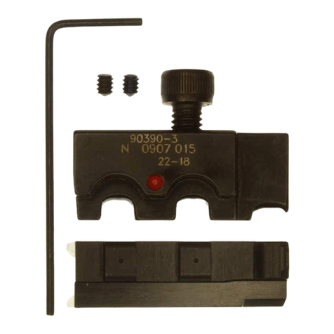
Tyco Electronics 90390-3 User manual

Tyco Electronics
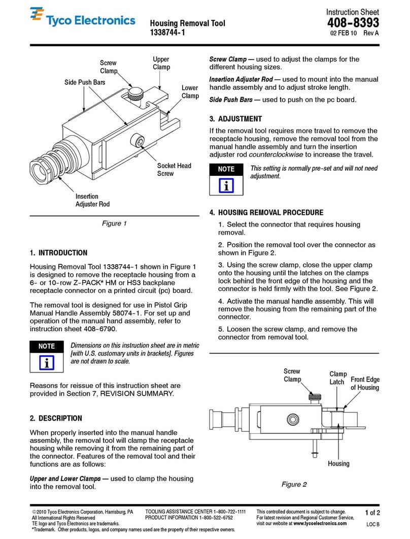
Tyco Electronics 1338744-1 User manual

Tyco Electronics
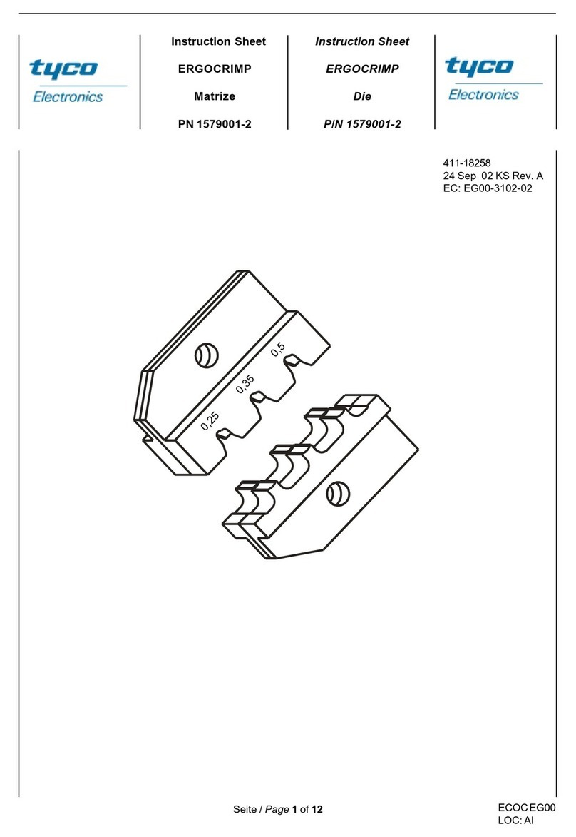
Tyco Electronics ERGOCRIMP User manual

Tyco Electronics
Tyco Electronics CXP 2161060-1 User manual

Tyco Electronics
Tyco Electronics CERTI- CRIMP 90720- 1 User manual

Tyco Electronics
Tyco Electronics 59239-4 User manual

Tyco Electronics
Tyco Electronics 411-15684 User manual

Tyco Electronics
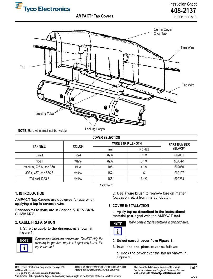
Tyco Electronics AMPACT 602080 User manual