manuals.online logo
Brands
  1. Home
  2. •
  3. Brands
  4. •
  5. Wavecom
  6. •
  7. Modem
  8. •
  9. Wavecom WMOD2B User manual

Wavecom WMOD2B User manual

Other manuals for WMOD2B

1

Other Wavecom Modem manuals

Wavecom SAM 3G Plus User manual

Wavecom

Wavecom SAM 3G Plus User manual

Wavecom WMOD2B User manual

Wavecom

Wavecom WMOD2B User manual

Wavecom WMOi3 User manual

Wavecom

Wavecom WMOi3 User manual

Wavecom Fastrack M1200 series User manual

Wavecom

Wavecom Fastrack M1200 series User manual

Wavecom FASTRACK M1306B User manual

Wavecom

Wavecom FASTRACK M1306B User manual

Wavecom WMOi3 User manual

Wavecom

Wavecom WMOi3 User manual

Wavecom WMO1-G900 User manual

Wavecom

Wavecom WMO1-G900 User manual

Wavecom SAM User manual

Wavecom

Wavecom SAM User manual

Wavecom G2 User manual

Wavecom

Wavecom G2 User manual

Wavecom WMO2 GSM 900 User manual

Wavecom

Wavecom WMO2 GSM 900 User manual

Wavecom WMO2 User manual

Wavecom

Wavecom WMO2 User manual

Wavecom Fastrack M1206 User manual

Wavecom

Wavecom Fastrack M1206 User manual

Popular Modem manuals by other brands

Paradyne COMSPHERE 3810 User guide supplement

Paradyne

Paradyne COMSPHERE 3810 User guide supplement

Zhone 6411-A1-xxx Technical specifications

Zhone

Zhone 6411-A1-xxx Technical specifications

Air 802 Linux USB?ADG?2 user guide

Air 802

Air 802 Linux USB?ADG?2 user guide

ETEK TD-8011 user manual

ETEK

ETEK TD-8011 user manual

Arris Touchstone CM8200 user guide

Arris

Arris Touchstone CM8200 user guide

3Com EtherLink 3C900B Installation and operating instructions

3Com

3Com EtherLink 3C900B Installation and operating instructions

Axxera DMH25 Operation manual

Axxera

Axxera DMH25 Operation manual

Lantronix M110 Series Command reference

Lantronix

Lantronix M110 Series Command reference

Megasat HD Stick 510se user manual

Megasat

Megasat HD Stick 510se user manual

Davicom DM562AP Operation manual

Davicom

Davicom DM562AP Operation manual

NetComm IG1000 Specifications

NetComm

NetComm IG1000 Specifications

Intelimax MA-2060 user manual

Intelimax

Intelimax MA-2060 user manual

ELPRO 905U-E user manual

ELPRO

ELPRO 905U-E user manual

SMC Networks D3CM1604V Administrator's manual

SMC Networks

SMC Networks D3CM1604V Administrator's manual

Telstra Wi-Fi 4G Advanced Pro X user guide

Telstra

Telstra Wi-Fi 4G Advanced Pro X user guide

Thrane&Thrane imarsat EXPLORER 300 user manual

Thrane&Thrane

Thrane&Thrane imarsat EXPLORER 300 user manual

Samsung AceLink SAM-335A user guide

Samsung

Samsung AceLink SAM-335A user guide

Enfora Enabler-G Integration guide

Enfora

Enfora Enabler-G Integration guide

manuals.online logo
manuals.online logoBrands
  • About & Mission
  • Contact us
  • Privacy Policy
  • Terms and Conditions

Copyright 2025 Manuals.Online. All Rights Reserved.

GB
Vi ringraziamo per la scelta fatta, sicuri che sarete soddisfatti del vostro acquisto.
Elenco materiale:
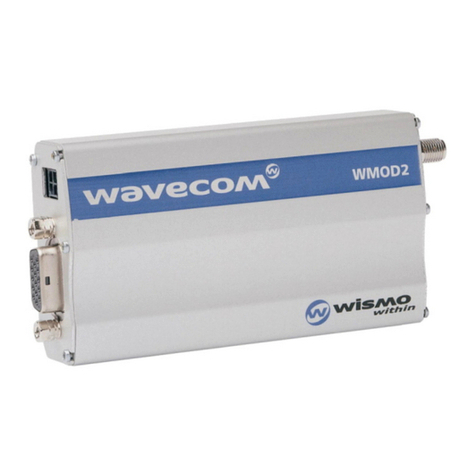
1. modem GSM WMO2 dual band
2. alimentatore
3. cavo di alimentazione con spina plug
4. cavo seriale 15/9 pin
5. antenna dual band base magnetica
6. adattatore SMA-FME per collegamento antenna
Accensione
a) inserimento Sim Card
b) collegamento antenna
c) collegamento all’ Host (Plantwatch/pCO/PC) con cavo seriale
d) accensione modem GSM
e) primi comandi “AT”
a) Inserimento Sim card
Premendo sul bottone giallo presente sul modem GSM vicino all’attacco
d’antenna si estrae il portasim dove deve essere alloggiata la Sim Card.
L’ inserimento corretto della scheda è guidato dalla forma del supporto
estraibile che ha un taglio in un angolo.
Alloggiata la Sim Card è possibile inserire il supporto nel modem tenendo
presente che i contatti della Sim Card devono essere rivolti verso l’alto.
b) Collegamento antenna
Il modem GMS ha un connettore d’antenna tipo SMA femmina a cui si
deve collegare l’adattatore presente nella confezione.
Avvitare l’adattatore SMA-FME sul modem GSM e successivamente il
cavo d’antenna facendo attenzione a non forzare troppo la chiusura
(la stretta manuale è sufficiente).
c) Collegamento all’ Host (Plantwatch/pCO/PC) con cavo seriale
cavo 4) 20cm db 15/9: collegare il lato maschio 15 poli al modem GSM ed
il lato 9 poli femmina al PC o ad un cavo seriale standard.
Nel caso del Plantwatch utilizzare l’adattatore PLW0PMD000.
d) Accensione modem GSM
Collegare il cavetto di alimentazione lato microfit 4 poli nel modem GSM e
inserire la presa di rete dell’alimentatore.
Prendere il connettore plug maschio del cavetto collegato al modem e
inserirlo nella presa plug femmina del cavo alimentatore.
Verificare che il led rosso presente sul modem lato sportello Sim Card si
accenda.
Thank you for your choice. We trust you will be satisfied with your purchase.
List of materials:
1. modem gsm wmo2 dual band
2. power supply
3. power supply cable with plug
4. serial cable 15/9 pin
5. magnetic base dualband antenna
6. adapter sma-fme for the antenna connection
Startup
a) Sim Card insertion
b) antenna connection
c) host connection (plantwatch/pco/pc) through serial cable
d) GSM modem startup
e) first commands “AT”
A) Sim Card insertion
Prewssing the yellow button placed on the gsm modem near to the
antenna connection you can take out the sim holder where the
Sim Card must be placed. The correct insertion of the card is helped by
the shape of the pull-out bearing, which is cut in a corner.
Once housed the Sim Card, it is possible to insert the bearing in the
modem reminding that the contacts of the simcard must be turned upwards.
B) Antenna connection
The GSM modem is fitted with a female sma type antenna connector to
which the adapter contained in the packaging must be connected.
Screw the SMA-FME adaptor in the gsm modem and then the antenna
cable paying attention not to force too much the closing (the manual hold
is sufficient).
C) Host connection (Plantwatch/pCO/PC) through serial cable
Cable 4) 20cm db 15/9: connect the 15-pole male side to the GSM
modem and the 9-pole female side to the pc or to a standard serial cable.
In case of the Plantwatch, use the PLW0PMD000 adapter.
d) GSM modem startup
Connect the 4-pole microfit side power supply cable to the GSM modem
and insert the plug of the power supply.
Insert the male plug connector of the cable connected to the modem in
the female plug of the power supply cable.
Check that the red led, which is placed on the Sim Card door side of the
modem, turns on.
cod. +050000210 - rel. 1.0 - del. 07/09/01
Guida all’installazione modem Wavecom WMOD2B dual band 900/1800 - Installation manual of the Wavecom WMOD2B dual band 900/1800 modem
GB
1
2
5
3
4
6
GB
Per le segnalazioni del led rosso fare riferimento allo “User manual” del
modem disponibile in internet all’indirizzo del produttore www.wavecom.com.
Test del modem tramite un personal computer
Predisporre il PC con un programma di emulazione terminale es. Hyper Terminal
di Windows configurato nel seguente modo:
velocità di linea 9600 bit/s
parità nessuna
bit dati 8
bit stop 1
controllo di flusso nessuno
Per verificare il corretto collegamento e impostazione della porta dare il
comando “AT” invio e ricevere “OK”.
Azione Comando Risposta
lettura campo AT + CSQ +CSQ: xx,yy
lettura operatore AT + COPS? COPS:0,2,num. operatore
lettura centro servizi per sms AT + CSCA? CSCA: num. centro servizi
chiamata dati ATD numero connect
chiamata voce ATD numero; OK
risposta a “ring” ATA OK
settaggio vel. seriale AT + IPR= velocità OK
salvataggio parametri modif. AT & W OK
trasmettere SMS AT + CMGS= num. destinatario > (prompt per il messaggio)
scrivere SMS > “ciao come stai” Ctrl Z OK
leggere SMS AT + GMGR= num. SMS “ciao come stai”
notificato con GMTI: x
cancellare SMS AT + CMGD= num. SMS notificato OK
Per ogni altra funzione, utilizzo e impostazione si rimanda alla lettura del
manuale comandi AT.
For the red led signallings refer to the “User manual”of the modem that is
available in internet at the manufacturer’s site www.wavecom.com.
Modem test through a personal computer
Prearrange the PC with a terminal emulation program for ex. Windows Hyper
Terminal configured as the following:
line speed 9600 bit/s
parity none
data bits 8
stop bit 1
flow control none
to check the right connection and setting of the door, press “AT” enter and
receive “OK”.
Action Command Answer
read field AT + CSQ +CSQ: xx,yy
read provider AT + COPS? COPS: 0,2, provider number
read sms service centre AT + CSCA? CSCA: service centre number
data call ATD number connect
voice call ATD number; OK
“ring” answer ATA OK
set serial speed AT + IPR= speed OK
save modified parameter AT & W OK
send SMS AT + CMGS= addressee number > (message prompt)
write SMS > “hi, how are you” Ctrl Z OK
read SMS AT + GMGR= SMS number “hi, how are you”
notified by GMTI:x
erase SMS AT + CMGD= notified SMS number OK
For any other function, use and setting refer to the reading of the at command
manual.
cod. +050000210 - rel. 1.0 - del. 07/09/01