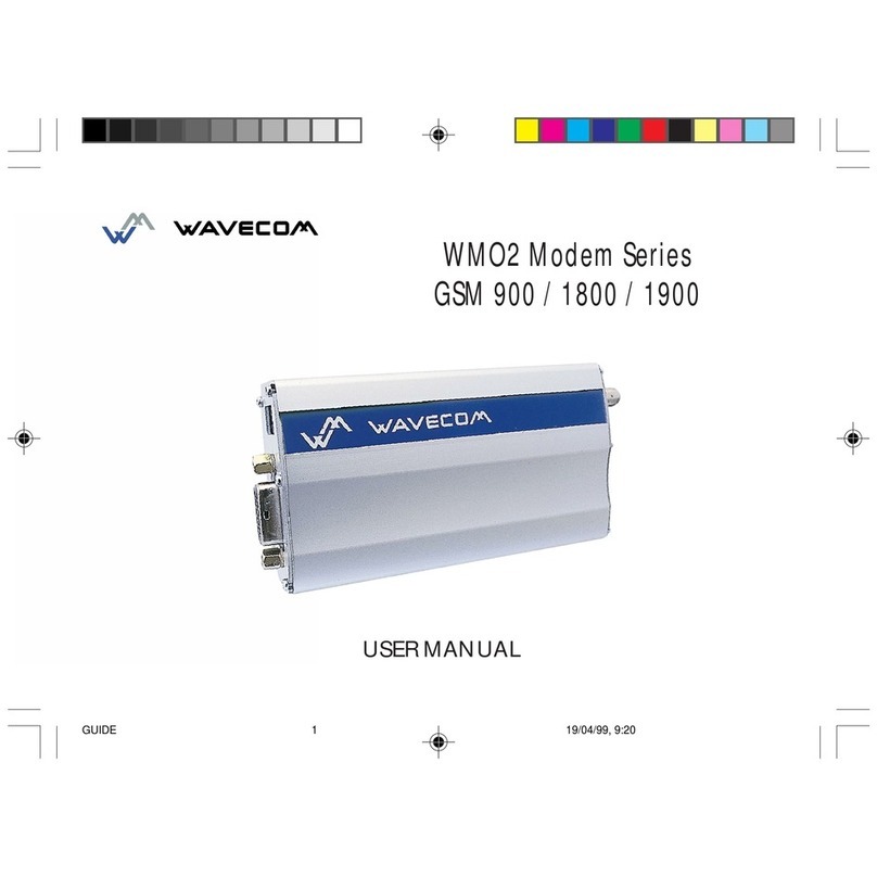
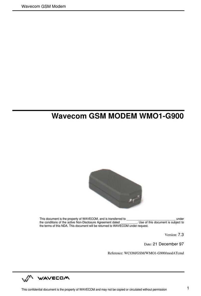
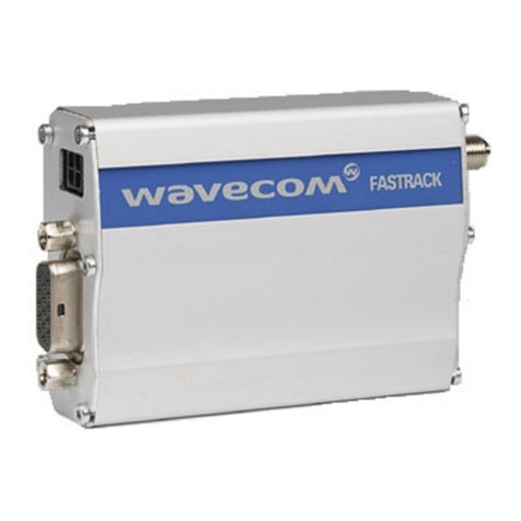
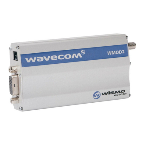
Wavecom WMO2 User manual

39 rue du Gouverneur Général Eboué
92130 Issy les Moulineaux
Tél: 01 46 29 08 00
Fax: 01 46 29 08 08
www.wavecom.com
WMO2 G900 / G1800 / G1900
GSM MODEM
Version:
1.0
Date:
Friday 21 May 1999
Reference:
WCOM/GSM/WMO2/WMO2ATDOC

WMO2 G900 / G1800 / G1900
WCOM/GSM/WMO2/WMO2ATDOC Friday 21 May 1999
WAVECOM confidential © ii
Document amendments
Issue Date Status Author Comments
1.1 21-05-99 PC. Guillemin
N. Higelin
O. Capron
F. Desnoues
D. Martinez
Creation

WMO2 G900 / G1800 / G1900
WCOM/GSM/WMO2/WMO2ATDOC Friday 21 May 1999
WAVECOM confidential © iii
Contents
1Introduction............................................................................1
1.1 Document scope ........................................................................... 1
1.2 Related documents........................................................................ 1
1.3 Definitions..................................................................................... 2
1.4 Acronyms and abbreviations......................................................... 2
2Technical Data........................................................................3
2.1 Basic offer ..................................................................................... 3
2.1.1 Contents....................................................................................... 3
2.1.2 Packaging..................................................................................... 3
2.1.3 User manual ................................................................................. 3
2.2 Accessories ................................................................................... 3
2.2.1 Cordons........................................................................................ 3
2.2.2 Headset........................................................................................ 4
2.2.3 Antenna ....................................................................................... 4
2.2.4 Power supply................................................................................ 4
2.3 Options ......................................................................................... 4
2.3.1 Car Kit .......................................................................................... 4
2.4 Product references......................................................................... 4
2.4.1 Ordering references....................................................................... 4
2.4.2 Markings and Labels..................................................................... 4
2.5 Physical characteristics ................................................................. 6
2.5.1 Shape........................................................................................... 6
2.5.2 Mechanical philosophy.................................................................. 7
2.6 Conditions of use........................................................................... 8
2.6.1 Climatic and mechanical environment............................................ 8
2.6.2 Electrical environment................................................................... 9
2.7 Electrical characteristics .............................................................. 10
2.8 Connectors.................................................................................. 11
2.8.1 Connector location...................................................................... 11
2.8.2 Connectors description................................................................ 11
2.9 Capabilities.................................................................................. 13
2.10 Accessories description............................................................. 13
2.10.1 Headset...................................................................................... 13
2.10.2 Serial link.................................................................................... 13
2.10.3 Serial and audio link.................................................................... 14
2.10.4 Remote Modem Control Link ....................................................... 15
2.10.5 Power supply cordon .................................................................. 15
2.10.6 Cables pinning............................................................................ 16
3AT Commands interface........................................................17
3.1 Command syntax ........................................................................ 17
3.1.1 Request syntax........................................................................... 18
3.1.2 Answer syntax............................................................................ 19
3.2 Default settings........................................................................... 20

WMO2 G900 / G1800 / G1900
WCOM/GSM/WMO2/WMO2ATDOC Friday 21 May 1999
WAVECOM confidential © iv
3.3 Global behaviour ......................................................................... 21
3.3.1 SIM Insertion, SIM Removal ........................................................ 21
3.3.2 Background initialisation ............................................................. 22
4Commands set......................................................................23
4.1 General commands ..................................................................... 23
4.1.1 Manufacturer identification +CGMI.............................................. 23
4.1.2 Request model identification +CGMM.......................................... 23
4.1.3 Request revision identification +CGMR ........................................ 23
4.1.4 Product Serial Number +CGSN.................................................... 24
4.1.5 Select TE character set +CSCS .................................................... 24
4.1.6 Request IMSI +CIMI.................................................................... 24
4.1.7 Card Identification +CCID........................................................... 25
4.1.8 Capabilities list +GCAP................................................................ 25
4.1.9 Repeat last command A/ ............................................................. 25
4.1.10 Power off +CPOF........................................................................ 25
4.1.11 Set phone functionality +CFUN.................................................... 26
4.1.12 Phone activity status +CPAS ....................................................... 27
4.1.13 Report Mobile Equipement errors +CMEE .................................... 27
4.1.14 Extended error report +CEER....................................................... 27
4.2 Call Control commands ............................................................... 28
4.2.1 Dial command D......................................................................... 28
4.2.2 Hang-Up command H ................................................................. 29
4.2.3 Answer a call A........................................................................... 30
4.2.4 Remote disconnection................................................................. 30
4.2.5 DTMF signals +VTD, +VTS ......................................................... 30
4.2.6 Redial last number ATDL............................................................. 30
4.2.7 Automatic answer ATS0 ............................................................. 31
4.2.8 Incoming Call Bearer +CICB......................................................... 31
4.2.9 Gain control +VGR, +VGT............................................................ 32
4.2.10 Microphone Mute Control +CMUT.............................................. 32
4.2.11 Speaker & Microphone selection +SPEAKER ................................ 33
4.2.12 Echo Cancelation +ECHO ............................................................ 34
4.2.13 SideTone modification +SIDET .................................................... 34
4.3 Network service related commands............................................. 35
4.3.1 Signal Quality +CSQ ................................................................... 35
4.3.2 Operator selection +COPS........................................................... 36
4.3.3 Network registration +CREG........................................................ 37
4.3.4 Read operator name +WOPN....................................................... 37
4.3.5 Preferred operator list +CPOL ...................................................... 38
4.4 Security commands..................................................................... 39
4.4.1 Enter PIN +CPIN ........................................................................ 39
4.4.2 Enter PIN2 +CPIN2...................................................................... 41
4.4.3 PIN remaining attempt number +CPINC...................................... 41
4.4.4 Facility lock +CLCK...................................................................... 42
4.4.5 Change password +CPWD.......................................................... 43
4.5 Phonebook commands................................................................ 44
4.5.1 Select phonebook memory storage +CPBS................................... 44
4.5.2 Read phonebook entries +CPBR .................................................. 44
4.5.3 Find phonebook entries +CPBF.................................................... 44
4.5.4 Write phonebook entry +CPBW ................................................... 45
4.5.5 Phonebook phone search +CPBP................................................. 46
4.5.6 Move action in phonebook +CPBN............................................... 47
4.5.7 Subscriber number +CNUM ........................................................ 48
4.5.8 Avoid phonebook init +WAIP....................................................... 48
4.6 Short Message Service commands.............................................. 49
4.6.1 Parameters definition .................................................................. 49
4.6.2 Select message service +CSMS................................................... 50
4.6.3 Preferred Message Storage +CPMS............................................. 50
4.6.4 Preferred Message Format +CMGF.............................................. 51
4.6.5 Save Settings +CSAS.................................................................. 51
WMO2 G900 / G1800 / G1900
WCOM/GSM/WMO2/WMO2ATDOC Friday 21 May 1999
WAVECOM confidential © v
4.6.6 Restore settings +CRES............................................................... 51
4.6.7 Show text mode parameters +CSDH ........................................... 52
4.6.8 New message indication +CNMI.................................................. 52
4.6.9 Read message +CMGR ............................................................... 53
4.6.10 List message +CMGL.................................................................. 54
4.6.11 Send message +CMGS ............................................................... 55
4.6.12 Write Message to Memory +CMGW............................................ 56
4.6.13 Send Message From Storage +CMSS .......................................... 57
4.6.14 Set Text Mode Parameters +CSMP.............................................. 58
4.6.15 Delete message +CMGD ............................................................. 58
4.6.16 Service center address +CSCA..................................................... 59
4.6.17 Select Cell Broadcast Message Types +CSCB............................... 59
4.6.18 Cell Broadcast Message Identifiers +WCBM................................. 59
4.7 Supplementary Services commands............................................ 60
4.7.1 Call forwarding +CCFC................................................................ 60
4.7.2 Call barring +CLCK...................................................................... 61
4.7.3 Modify SS password +CPWD...................................................... 61
4.7.4 Call waiting +CCWA ................................................................... 62
4.7.5 Calling line identification restriction +CLIR ................................... 63
4.7.6 Calling line identification presentation +CLIP................................ 63
4.7.7 Connected line identification presentation +COLP........................ 64
4.7.8 Advice of charge +CAOC............................................................. 65
4.7.9 Accumulated call meter +CACM.................................................. 65
4.7.10 Accumulated call meter maximum +CAMM................................. 66
4.7.11 Price per unit and currency table +CPUC...................................... 66
4.8 Data commands.......................................................................... 67
4.8.1 Bearer type selection +CBST ....................................................... 67
4.8.2 Service reporting control +CR...................................................... 67
4.8.3 Cellular result codes +CRC .......................................................... 68
4.8.4 Radio link protocol parameters +CRLP ......................................... 68
4.9 V24-V25 commands.................................................................... 69
4.9.1 Fixed DTE rate +IPR.................................................................... 69
4.9.2 DTE-DCE character framing +ICF................................................. 70
4.9.3 DTE-DCE local flow control +IFC.................................................. 71
4.9.4 Set DCD signal &C...................................................................... 71
4.9.5 Set DTR signal &D...................................................................... 71
4.9.6 Set DSR signal &S ...................................................................... 72
4.9.7 Back to online mode O ................................................................ 72
4.9.8 Result code suppression Q.......................................................... 72
4.9.9 DCE response format V ............................................................... 72
4.9.10 Default configuration Z................................................................ 72
4.9.11 Save configuration &W ............................................................... 72
4.9.12 Auto-tests &T............................................................................. 73
4.10 Specific AT commands ............................................................. 73
4.10.1 Cell environment description +CCED........................................... 73
4.10.2 Automatic RxLev indication +CCED ............................................. 74
4.10.3 General Indications +WIND ......................................................... 75
4.10.4 Data ciphering mode between ME and MSC +ALEA.................... 75
4.10.5 Data ciphering mode +CRYPT..................................................... 76
4.10.6 Key management +EXPKEY ......................................................... 76
4.10.7 Informations on PLMN +CPLMN.................................................. 76
4.10.8 Analog digital converters measurements +ADC........................... 76
4.10.9 Mobile Equipment event reporting +CMER................................... 76
4.10.10 Read Language Preference +WLPR.............................................. 77
4.10.11 Write Language Preference +WLPW ............................................ 77
4.10.12 Read GPIO value +WIOR ............................................................. 77
4.10.13 Write GPIO value +WIOW............................................................ 77
4.11 Other AT commands................................................................. 77
4.11.1 V.25 ter recommandation............................................................ 77
4.11.2 GSM 07.05 recommandation....................................................... 77
4.11.3 GSM 07.07 recommandation....................................................... 77
4.12 Fax Management commands.................................................... 78

WMO2 G900 / G1800 / G1900
WCOM/GSM/WMO2/WMO2ATDOC Friday 21 May 1999
WAVECOM confidential © vi
4.12.1 Setting up the module for fax ...................................................... 78
4.12.2 Setting up the PC fax application:................................................ 78
4.12.3 Restoring the module's default profile for data call........................ 78
5Miscellaneous.......................................................................79
5.1 Disclaimer ................................................................................... 79
5.2 Trademarks ................................................................................. 79
5.3 Copyright .................................................................................... 79
6Appendices...........................................................................80
6.1 ME error result code: +CME ERROR: <error>.............................. 80
6.2 Message service failure result code: +CMS ERROR: <er> ........... 80
6.3 Specific error result codes ........................................................... 81
6.4 IE Cause values from GSM 04.08 recommendation..................... 82
6.5 GSM 04.11 Annex E-2: Mobile originating SM-transfer.............. 84
6.6 Unsolicited result codes............................................................... 85
6.7 Final result codes ........................................................................ 85
6.8 Intermediate result codes ............................................................ 86
6.9 Operator names........................................................................... 87

WMO2 G900 / G1800 / G1900
WCOM/GSM/WMO2/WMO2ATDOC Friday 21 May 1999
WAVECOM confidential © 1
1Introduction
This document is intended for every person being brought to work with the
modem WISMO WMO2 G900, G1800 or G1900.
1.1 Document scope
This document presents the technical characteristics of the connections,
interfaces and power supply of the modem WISMO WMO2 in the G900,
G1800 and G1900 terminal version.
This document describes the AT commands allowing the user to issue
communications in the voice, data or fax mode with the modem WISMO
WMO2 G900, G1800 and G1900 and for SMS's reception and expedition.
1.2 Related documents
This interface document is based on the following recommendations and
reference documents:
[1]ETS 300 019 Environmental conditions and environmental tests
for telecommunications equipment.
[2]SAE J1113 Transients Voltage Suppression in Automotive
Vehicle.
[3]WAVE Internal Qualification Plan version 1.1.
[4]ETSI GSM 07.05 European digital cellular telecommunication
system (phase 2); Use of DTE-DCE interface for
Short message service and cell broadcast service
[5]ETSI GSM 07.07 European digital cellular telecommunication
system (phase 2); AT command set for GSM
Mobile Equipment
[6]ITU-T V.25 ter. Serial asynchronous automatic dialling and control
[7]ETSI GSM 03.40 European digital cellular telecommunication
system (phase 2); Technical realisation of the
Short Message Service (SMS) Point-to-Point (PP)
[8]ETSI GSM 03.38 European digital cellular telecommunication
system (phase 2); Alphabets and language-
specific information
[9]WMO2sp14 Technical characteristics of the WMO2 modem
line.
[10]SII015 v7.9 AT-Commands interface layer specification for the
phase 2 software of the WMO2 modem line.

WMO2 G900 / G1800 / G1900
WCOM/GSM/WMO2/WMO2ATDOC Friday 21 May 1999
WAVECOM confidential © 2
1.3 Definitions
For the purposes of the AT-commands interface description in this
document, the following definitions apply:
Command mode: In Command mode, the modem is not
communicating with a remote station, and is ready
to accept commands. When powering-up, the
modem automatically enters this mode, and
automatically returns to this mode when a call is
disconnected.
Online mode: Also called data mode: In Online mode, the modem
is communicating with a remote station. Data
coming through the RS232 serial link are treated as
data and transmitted to the called part, and data
received from the called part are transmitted to the
terminal through the RS232 serial link. Online mode
is activated by successful completion of a command,
either manually or automatically, to originate or
answer a call, or by receiving the ATO command to
return to online mode from Command mode.
[...]: Items enclosed in square brackets are optional.
The square brackets themselves must not appear in
the command line.
<...>:Some syntactical elements are mentioned enclosed
in angle brackets. Actually the meaning (values) for
those elements must appear in the command and
the angle brackets are omitted.
All other characters, including " " ", "&", "?", "==", parentheses, etc., shall
appear in commands as written.
1.4 Acronyms and abbreviations
For the purposes of the AT-commands interface description in this
document, the following abbreviations apply:

WMO2 G900 / G1800 / G1900
WCOM/GSM/WMO2/WMO2ATDOC Friday 21 May 1999
WAVECOM confidential © 3
2Technical Data
This section deals with the specifications of the second generation of
Wavecom's GSM modem. Under the generic reference WMO2-GXXXX are 3
different modems grouped: WMO2-G900 for GSM standard, WMO2-G1800
for DCS standard and WMO2-G1900 for PCS standard.
All these modems are based on WISMO concept, it means each modem
includes a WISMO1B-Gxxxx module.
In this section you will find, on the one hand the description of the basic
modem offer and, on the other hand several accessories description.
2.1 Basic offer
2.1.1 Contents
The basic offer comprises the following elements:
•Modem
•Mechanical fixation (holding bridle)
•Power supply cable + fuse
•User manual
2.1.2 Packaging
The Basic offer set is presented in a unique conditioning, Which external
dimensions are close to the following values:
70mm (width) x 60mm (height) x135mm (length).
This is a cardboard box. It is build-in small waves, which are covered with
a thin film of white ice-cold paper.
2.1.3 User manual
The user manual is realised in a size closed to the following values:
105mm (width) x 148,5 mm (height) (that is 1/2 A5).
It contains twenty-two pages except the cover page.
2.2 Accessories
2.2.1 Cordons
Two cordons could be proposed:
•serial link and audio cable (Y cordon) for a low power audio solution (for
example: headset, phone receiver, ...),
•serial link and audio cable (Y cordon) for Car Kit option that is with a
higher power on the audio part.

WMO2 G900 / G1800 / G1900
WCOM/GSM/WMO2/WMO2ATDOC Friday 21 May 1999
WAVECOM confidential © 4
2.2.2 Headset
The headset allows audio hands free function. This feature implements a
weak power speakerphone and a microphone.
TBD: standard products
2.2.3 Antenna
Two solutions could be proposed:
•a standard deported cellular phone antenna,
•a WAVECOM designed short antenna.
2.2.4 Power supply
An AC/DC converter (220V~ / 12V-2A) enables a direct powering on the
power network.
2.3 Options
2.3.1 Car Kit
Thanks to an audio power amplifier, a microphone - that can be fixed on a
vehicle's sun visor - and a loud speaker - that can be fixed on the vehicle
dashboard -, one can obtain a hands free embedded solution.
Speaker (8Ω) and directional microphone are supplied with this option.
2.4 Product references
2.4.1 Ordering references
The WMO2 modem product line references are set up using the
WMO2-GXXXX base.
The references respect the following syntax:
•WMO2-G900 for the GSM 900 standard;
•WMO2-G1800 for the DCS 1800 standard;
•WMO2-G1900 for the PCS 1900 standard.
2.4.2 Markings and Labels
2.4.2.12.4.2.1 Product labelProduct label
This label is built with anodise aluminium. It has a blue silk screen
treatment (marking: aluminium colour) and is fitted on the upper convex
mechanical side. It supports the WAVECOM logo.
Dimension: 96x10 mm.

WMO2 G900 / G1800 / G1900
WCOM/GSM/WMO2/WMO2ATDOC Friday 21 May 1999
WAVECOM confidential © 5
2.4.2.22.4.2.2 Production stickerProduction sticker
This label is located on the bottom side of the product and contains CE
marking (in order to improve the productivity on assembly line, this marking
will be printed or silk screen treated in advance).
Dimension: 60x9.5 mm.
2.4.2.32.4.2.3 CE and IMEI stickerCE and IMEI sticker
This label is placed on the bottom of the product, it contains the following
legible information
REF PROD: (WMO2-GXXX)
P/N (WMXXXXX)
and IMEI number in barre code.
This last one includes the product serial number.
Dimensions:60 x 9.5 mm.
2.4.2.42.4.2.4 Label packagingLabel packaging
This label is put on the product box and defines the contents.
REF PROD: WMO2-GXXX
P/N: WMxxxxx
IMEI
01650165
Made by Wavecom

WMO2 G900 / G1800 / G1900
WCOM/GSM/WMO2/WMO2ATDOC Friday 21 May 1999
WAVECOM confidential © 6
2.5 Physical characteristics
2.5.1 Shape
The physical shape is given as follow:
Physical characteristic Qualification Comments
Dimension
Absolute maximum dimension 98x54x25 mm
110x54x25 mm Without the connectors quotations.
Weight < 140 g
Volume 13.23 cm3
Case Aluminium profile

WMO2 G900 / G1800 / G1900
WCOM/GSM/WMO2/WMO2ATDOC Friday 21 May 1999
WAVECOM confidential © 7
2.5.2 Mechanical philosophy
The mechanical casing of the WMO2 modem line is built from an
aluminium profile ended by two stoppers at each edge.
All input/output interfaces are realised through three connectors
placed at the two extremities of the profile. No cordon is fixed to the
casing.
The SIM card (micro-SIM) is put on an extractable drawer.
A red LED indicates the functioning mode of the product.

WMO2 G900 / G1800 / G1900
WCOM/GSM/WMO2/WMO2ATDOC Friday 21 May 1999
WAVECOM confidential © 8
2.6 Conditions of use
2.6.1 Climatic and mechanical environment
The following figure shows environment standard constraints:
WMO2_Gxxxx
ENVIRONNEMENTALCLASSES
TYPEOFTEST STANDARDS STORAGE TRANSPORTATION OPERATING(PORTUSE)
Class1.2 Class2.3 Class7.3
Cold IEC68-2.1 -25°C 72h -40°C 72h -20°C 16h
Abtest
Dry heat IEC68-2.2 +70°C 72 h +70°C 72h +55°C 16h
Bbtest
Changeoftemperature IEC68-2.14 -40°/+30°C 5cycles -20°/+30°C 3cycles
Na/Nb test t1=3h t1=3 h
DampheatIEC68-2.30 +30°C 2cycles +40°C 2cycles +40°C 2cycles
cyclic Dbtest
90%-100%RH
90%-100%RH
90%-100%RH
variant1 variant1 variant1
DampheatIEC68-2.56 +30°C 4days +40°C 4days +40°C 4days
Cbtest
Sinusoidalvibration IEC68-2.6 5-62Hz : 5mm/s
Fctest 62-200Hz: 2m / s2
3x5sweepcycles
5-20Hz : 0.96m2/s3 10-12Hz : 0.96 m2/s3
Randomvibration IEC68-3.36 20-500Hz: -3 dB /oct12-150Hz: -3dB/oct
wideband Fdbtest3x10min 3x30min

WMO2 G900 / G1800 / G1900
WCOM/GSM/WMO2/WMO2ATDOC Friday 21 May 1999
WAVECOM confidential © 9
2.6.2 Electrical environment
The following table sums up electrical constraints in an automotive
environment:
Length of transient Cause
Energy
capability
Voltage
Amplitude
Possible
frequency of
application
Steady state Failed Voltage Regulator oo
+ 18 V
Infrequent
3 - 5 minutes Jump start with 24 V
battery oo
+/- 24 V
Infrequent
200ms to 400ms Load dump - i.e.,
disconnection of battery
while at high charging
rates
≥10 J
≤125V Infrequent
< 0.32 s Inductive Load
Switching Transient <1 J
-300V to +80V
Often
< 0.20 s Alternator Field Decay <1 J
-100V to -40V
Each Turn-Off
90ms Ignition Pulse, Battery
Disconnected <0.5 J
≤75V
<500Hz Several
Times in vehicle
Life
1ms Mutual Coupling in
Harness (Note) <1 J
<200V
Often
15µs Ignition Pulse, Normal <0.001 J
<3V
<500Hz
Continuous
Accessory Noise <1.5V 50 Hz to 10 kHz
Transceiver Feedback 20mV R.F.
Note: These transients may be present on any wire in the vehicle.

WMO2 G900 / G1800 / G1900
WCOM/GSM/WMO2/WMO2ATDOC Friday 21 May 1999
WAVECOM confidential © 10
2.7 Electrical characteristics
The following table summarises the electrical characteristics defined for the
different input/output connections.
Parameters MIN TYP MAX UNIT Comments
Power supply:
Input supply voltage
Input supply voltage with Car Kit option
Input peak supply current @5V*/ 6V**
Input average supply current @5V*/ 6V** in
communication mode
Input average supply current @5V*/ 6V**
in idle mode (paging period 480ms)
Input average supply current @5V*in idle
mode with auto-shutdown function***
5*/6** 13,5
13,5
32
18
2,5*/ 0,9**
450*/200**
35
10
V
V
A
mA
mA
mA
GSM or DCS/PCS
GSM or DCS/PCS
GSM or DCS/PCS
Serial link:
RS232 standard
Audio (head set):
microphone input current @2V/2KΩ
absolute microphone input voltage
speaker output current 150Ω//1nF
absolute speaker impedance
0,5
16
100
32
mA
mVpp
mA
Ω
SIM 3 5 V
*only GSM devices.
** only DCS and PCS devices.
*** auto shutdown function could be activate if the serial link leads a
non hardware flow-control (CTS/RTS non used). This hardware
feature will not be available with the first products.

WMO2 G900 / G1800 / G1900
WCOM/GSM/WMO2/WMO2ATDOC Friday 21 May 1999
WAVECOM confidential © 11
2.8 Connectors
2.8.1 Connector location
2.8.2 Connectors description
We considered the following constraints in the connector choice:
•Size;
•Mechanical characteristics;
•Electrical performances;
•Industrialisation (surface assembly choice).
In order to extract or insert the Micro SIM card, it is strongly
recommended to press with a sharp element (a pen for example) the SIM
holder ejector.
If this procedure is no respected, the SIM holder could be destroyed.

WMO2 G900 / G1800 / G1900
WCOM/GSM/WMO2/WMO2ATDOC Friday 21 May 1999
WAVECOM confidential © 12
Function
connector Type Pining Drawing Ref. supplier Mating connector
examples
RF connector SMA RADIALL:
R284310085 RADIALL:
R125073
Serial link
AUDIO link
BOOT
RESET
SUB D
High
Density
(15 pt.)
1DCD (CT109)
2TX (CT103)
6RX (CT104)
7DSR (CT107)
8DTR (CT108/2)
9GND
11 CTS (CT106)
12 RTS (CT105)
13 RI (CT125)
4MICROPHONE (+)
5MICROPHONE (-)
10 SPEAKER (+)
15 SPEAKER (-)
3BOOT
14 RESET
JST:
KSEY-15S-3B6L18-13
ITT CANNON:
ZDEA-15P-SB
or
JST:
KEC-15P
with contact JK-
SP2143
Power Supply
connector Micro-Fit
(4pts) 1 V+BATTERY
2 GROUND
3-4 AUXI MOLEX:
43045-0409 MOLEX:
43025-0400
SIM holder MOLEX:
52828-0611 MICRO SIM
1
2
3
4
5
6
7
8
9
1
0
1
5
1
4
1
3
1
1
1
2
4
3
2
1

WMO2 G900 / G1800 / G1900
WCOM/GSM/WMO2/WMO2ATDOC Friday 21 May 1999
WAVECOM confidential © 13
2.9 Capabilities
Functions of the WMO2 modem line are defined as follow:
GSM DCS/PCS
Standard 900 MHz.
Class 4 (2W).
GSM phase 2.
1800 MHz or 1900 MHz
Class 1 (1W)
GSM phase 2.
Interface Serial interface RS232 V.24/V.28
AT command set based on V.25ter and
GSM 07.05 & 07.07.
Auto-bauding function between baud
rates 2400 and 19200
No auto-framing available
Serial interface RS232 V.24/V.28
AT command set based on V.25ter and
GSM 07.05 & 07.07.
Auto-bauding function between baud rates
2400 and 19200
No auto-framing available
SMS Mobile Originated (MO) and Mobile
Terminated (MT). Text & PDU Mode
point to point. Cell broad cast.
In accordance with GSM 07.05
Mobile Originated (MO) and Mobile
Terminated (MT). Text & PDU Mode point
to point. Cell broad cast.
In accordance with GSM 07.05
Data Asynchronous 2400, 4800, 9600 baud
rates.
Transparent and Non Transparent mode
In Non Transparent Mode: 300, 1200,
1200/75 baud.
Mode 3.1 kHz (PSTN) and V110 (ISDN)
Asynchronous 2400, 4800, 9600 baud
rates.
Transparent and Non Transparent mode
In Non Transparent Mode: 300, 1200,
1200/75 baud.
Mode 3.1 kHz (PSTN) and V110 (ISDN)
Fax 2400/4800/7200/9600 baud, GSM
teleservice 62 in Transparent Mode.
Class 1.
Group 3 compatible.
2400/4800/7200/9600 baud, GSM
teleservice 62 in Transparent Mode.
Class 1.
Group 3 compatible.
Audio FR and EFR operation
1: Head Set
2: Car Kit (in option)
FR and EFR operation
1: Head Set
2: Car Kit (in option)
2.10 Accessories description
2.10.1Headset
To be defined.
2.10.2Serial link
SUB-D High Density
15 points male +
braid of shield
soldered on SUB D
body + cover.
SUB-D 9 points
female
+ braid of shield
soldered on SUB D
body + cover.
Shielded cable 9 wires + braid of shield:
Wire constitution: tinned copper 7x0.2 mm
Wire constitution: 7x 0.15 (26AWG)
Operating temperature range: -20°C/+85°C.
Cable length: 1,5 m

WMO2 G900 / G1800 / G1900
WCOM/GSM/WMO2/WMO2ATDOC Friday 21 May 1999
WAVECOM confidential © 14
2.10.3Serial and audio link
2.10.3.12.10.3.1 Low power audioLow power audio
2.10.3.22.10.3.2 High power audioHigh power audio
SUB-D High Density
15 points male +
braid of shield
soldered on SUB D
body + cover.
SUB-D 9 points
female
+ braid of shield
soldered on SUB D
body + cover.
Modular Jack
4P/4C
Shielded cable 9 wires + braid of shield:
Wire constitution: tinned copper 7x0.2 mm
Wire constitution: 7x 0.15 (26AWG)
Operating temperature range: -20°C/+85°C.
Flat cable 4 wires:
Wire constitution: tinned copper 7x0.15 mm (26AWG)
Operating temperature range: -20°C/+85°C
Cable length: 1,5 m
Jack audio mono 2,5 mm
female (microphone)
Shielded cable 9 wires + braid of shield:
Wire constitution: tinned copper 7x0.2 mm
Wire constitution: 7x0.15 (26AWG)
Operating temperature range: -20°C/+85°C
Cable2x2 wires:
2 Wires constitution (speaker): tinned copper 7x0.2 mm (24AWG)
1 conductor with shield (microphone)
Operating temperature range: -20°C/+85°C
Cable length: 1,5 m
Female RCA connector
(speaker)
SUB-D High Density 15
pts male + braid of
shield soldered on SUB
D body + cover SUB-D 9 pts female
+ braid of shield
soldered on SUB D
body + cover
This manual suits for next models
6
Table of contents
Other Wavecom Modem manuals

Wavecom
Wavecom WMOi3 User manual

Wavecom
Wavecom WMOD2B User manual

Wavecom
Wavecom WMO1-G900 User manual

Wavecom
Wavecom SAM 3G Plus User manual

Wavecom
Wavecom G2 User manual

Wavecom
Wavecom WMO2 GSM 900 User manual

Wavecom
Wavecom WMOi3 User manual

Wavecom
Wavecom FASTRACK M1306B User manual

Wavecom
Wavecom WMOD2B User manual

Wavecom
Wavecom Fastrack M1206 User manual