Wavetek 3000 User manual

INSTRUCTION
MANUAL
MODEL
3000
SIGNAL
GENERATOR
WAvaTE
K

INSTRUCTION
MANUAL
MODEL
3000
SIGNAL
GENERATOR
Serial
No
.
/2_5
q
s
1
THIS
DOCUMENT
CONTAINSINFORMATION
PROPRIETARY
TO
WAVETEK
.
THE
INFORMATION
IN
THIS
DOCUMENT
IS
NOT
TO
BE
USED
OR
DUPLICATED
IN
ANY
MANNER
WITHOUT
THE
PRIOR
APPROVAL,
IN
WRITINGOF
WAVETEK
.
WAVETEK
RF
PRODUCTS,
INC
.
5808
CHURCHMAN
BY-PASS
INDIANAPOLIS,
IN
46203-6109
TEL
.
317/788-9351
TLX
:
(INST
.)
6842041
FAX
:
317/788-5999
2-88

WARRANTY
All
Wavetek
instruments
are
warranteed
against
defects
in
material
and
workmanship
for
a
period
of
one
year
after
date of
manufacture
.
Wavetek
agrees to
repair
or
replace
any
assembly
or
component
(except
batteries)
found
to
be
defective
under
normal
use
during
this
period
.
Transfermatic
Switch
assemblies,
manufactured
by Wavetek,
are
unconditionally
warranteed
for
the
life
of the
instrument
.
Wavetek's
obligation
under
this
warranty
is
limited
solely
to
repairing
any
such
instrument
which,
in
Wavetek's
sole
opinion,
proves
to
be
defective
within
the
scope
of
the
warranty
when
returned
to
the
factory or to an
authorized
service
center
.
Transportation
to
the
factory
or
service
center
is
to
be
prepaid
by
purchaser
.
Shipment
shouldnot
be
made
without
prior
authorization
by
Wavetek
.
This
warranty
does
not
apply
to
any
products
repaired
or
altered
by
persons
not
authorized
by
Wavetek,
or
not
in
accordance
with
instructions
furnished
by
Wavetek
.
If
the
instrument
is
defective
as a
result
of misuse,
improper
repair,
or
abnormal
conditions
or operations,
repairs
will
be
billed at
cost
.
Wavetek
assumes
no
responsibility
for
its
product
being
used
in
a
hazardous
or
dangerous
manner
either
alone
or
in
conjunctionwith
other
equipment
.
High
voltage
used
in
some
instruments
may
be
dangerous
if
misused
.
Special
disclaimers
apply
to these
instruments
.
Wavetek
assumes
no
liability
for
secondary
charges
or
consequential
damages
and,
in
any
event,
Wavetek's
liability
for
breach
of
warranty
under
any
contract
or
otherwise
shall
not exceed the
purchase
price
of the
specific
instrumentshipped
and
against
which
a
claim
is
made
.
Any
recommendations
made
by
Wavetek
for
use
of
its
products
are
based
upon
tests
believed to
be
reliable,
but
Wavetek
makes
no
warranty
of the
results
to be
obtained
.
This
warranty
is
in
lieu
of
all
other
warranties,
expressed
or implied,
and
no
representative
or
person
is
authorized
to
represent or
assume
for
Wavetek
any
liability
in
connection
with
the
sale
of
our
products
other
than
set
forth herein
.
SCOPE
OF
THIS
MANUAL
This
manual
provides
descriptive
material
and
instructions
for the
installation,
operation,
main-
tenance,
and
repair
of the
WAVE
-
I
EK
Model
3000
Signal
Generator

SECTION
1
SECTION
2
SECTION
3
SECTION
4
CONTENTS
GENERAL
INFORMATION
1
.1
INTRODUCTION
.....
....
.... .
1-1
1
.2
SPECIFICATIONS
.....
.
.
...
. .
1-2
1
.3
OPTIONS
.
.....
......
....
.
1-4
1
.4
ACCESSORIES
.
....
......
...
.
1-4
OPERATION
2
.1
INTRODUCTION
......
...
.....
2-1
2
.2
MECHANICAL
INSTALLATION
. .
.
......
2-1
2
.3
ELECTRICAL
INSTALLATION
. .
...
....
2-2
2
.4
DESCRIPTION
OF
FRONTPANEL
. .
...
. .
2-2
2 .5
DESCRIPTION
OF
REARPANEL
....
...
.
2-4
2.6
INSTALLATION
CHECKS
........
. .
2-5
2 .7
OPERATING
PROCEDURE
...
.......
.
2-7
THEORY
OF
OPERATION
3
.1
INTRODUCTION
.
........
. .
...
3-1
3
.2
OVERALLBLOCKDIAGRAM
.....
... .
.
3-1
3 .3
C315
- METERBOARD
.
........
.
.
3-8
3 .4
C316
-
MODULATION
BOARD
.......
. .
3-9
3 .5
DPS2A-
POWER
SUPPLY
. .
.
.
......
3-10
3
.6
DELETED
.
.
. .
......
3-10
3
.7
M9W
-
SWEEP
OSCILLATOR
.
...
.....
3-11
3
.8
M10W
-
OUTPUT
AMPLIFIER
. .
...
....
3-12
3
.9
M172
-
SWEEP
DRIVE/DAC
.....
....
3-13
3
.10
M29-1
FM REFERENCE
........
. .
.
3-14
3
.11
M30
-
CRYSTAL
SOURCE
.......
.
.
.
3-15
3
.12
M31
-
kHz
STEPS
.
...........
.
3-16
3
.13
M32 - MHz
STEPS
.
.
...........
3-17
3
.14
M33
-
NARROW
OSCILLATOR
LOCK
......
3-19
3
.15
M34
-
WIDE
OSCILLATOR
LOCK
.......
3-20
PERFORMANCE
TESTS
4 .1
INTRODUCTION
.. .......... . .
4-1
4 .2
FREQUENCY
RANGE
AND
RESOLUTIONTEST
. . .
4-2
4.3
FREQUENCY
ACCURACYTEST
.........
4-3
4.4
FREQUENCY
STABILITY
TEST
........
4-5
4.5
OUTPUT
LEVELACCURACY
TESTS
.......
4-5
4 .6
HARMONICS
TEST
...... .
.
.....
4-11
4
.7
NON-HARMONIC
TEST
....... .....
4-12
4
.8
RESIDUAL
AM
TEST
.........
.
..
4-14
4
.9
RESIDUAL
FM TEST
........... .
4-15
4
.10
INTERNAL
MODULATION
FREQUENCYTEST
...
4-16
4
.11
PERCENTAM ACCURACYTEST
........
4-17
4
.12
AM
BANDWIDTHTEST
. .
...
.......
4-19
4
.13
AM
DISTORTION
TEST
.
...
.......
4-21
4
.14
FM
DEVIATION
ACCURACY
TEST
...
....
4-22
4
.15
FM BANDWIDTH
TEST
.....
.....
..
4-23

CONTENTS
CONTINUED
4
.16
FM
DISTORTION
TEST
..... ......
4-25
4
.17
IMPEDANCE
TEST
.....
.
.....
.
.
4-26
4
.18
RFI
TEST
....... .
.
....." "
4-27
SECTION
5
MAINTENANCE
5 .1
INTRODUCTION
.
.
.
.......
.
. .
.
5-1
5
.2
SERVICE
INFORMATION
..... .....
5-1
5
.3
CALIBRATION
PROCEDURE
... ......
5-3
5
.4
TROUBLESHOOTING
....
.
.......
5-7
SECTION
6
REPLACEABLE
PARTS
6 .1
INTRODUCTION
.. ..........
. .
6-1
6
.2
MANUFACTURER'S
CODE
......
... .
6-1
SECTION
7
SCHEMATICS
7
.1
INTRODUCTION
.
....
...
..""."
7-1
7
.2
SCHEMATICNOTES
. .
...
.......
7-1
7 .3
ABBREVIATION
CODE
....
.......
7-2
7 .4
SCHEMATIC
INDEX
...
.......
. .
7-2
SECTION
8
MANUAL
CHANGES
AND
OPTIONS
8
.1
INTRODUCTION
.
......
....
.."
8-1
8
.2
MANUAL
CHANGES
......
. .
.....
8-1
8 .3
OPTIONS
. .
......
...
.....
8-1

1
.1
INTRODUCTION
The
Model3000
is
a
rugged,
completely
solid-state
Signal
Generator
covering
the
frequency
range
of
1
to
520
MHz
.
The
output
can
be
amplitude
or
frequency
modulated
and the
level
canbe
set
be-
tween
+13
and
-137dBm
.
1
.1 .1
FrequencyCharacteristics
The
frequency
of
the
unit
is
set
via
6
front
panel
lever/indicator
switches
which
yield
a
resolution
of
1
kHz
.
In
addition,
remote
frequency program
mability
is
standard
.
Thisfeaturemakes
the
Mode1
.3000
Signal
Generator
ideally
suited
for
both
semi
and
fullyautomatic
test
applications
.
The
accuracy
of
the
instrument
is
based
on a
crystal-controlled
oscillator
that
serves
as
a
stable
frequency
source
for
the
derivation
of
various
reference
frequencies
.
Thesereference
frequencies
arefed
to
phase lockedloops
that
enable
the
Model
3000
to
provide
high
stability
signals
to an
accuracy
of
0
.0017
over
its
specified
1
MHz
to
520
MHz range
.
In
the
CW
and
AM
modes
of
operation
the
overallaccuracy
of
the
unit
is
0
.0017
including
short
term
drift,
long term
drift,
incidental
FM
and
variations
due
to
line
voltage
changes
and
temperature
changes
.
In
the
FM
mode,
the
frequency
is
accurate
to
0
.0017
t10
kHzup
to
5
kHz
peak
deviation
and
0
.0017
t45 kHz
up
to
500 kHz
peak
deviation
.
1
.1
.2
ModulationFeatures
TheModel
3000also
featuresboth
inter-
nal
and
external
amplitude
and
frequency
SECTION
1
GENERAL
INFORMATION
modulation
capabilities
.
Internal
modulation
frequencies
of
400
Hz
and
1
kHz
are
available
.
In
the
FM mode
of
operation,
peakdeviations
up to
500
kHz
are
attainable
.
In
the
AM mode
amp-
litude
modulation
to
907
is
-
attainable
.
With
the
MODULATIONMODE
switch
in
either
of
the
FM
positions
and
the
MODULATION
FREQUENCY
switch
in
the
vernier
posi-
tion,
the
front panel slide
control
po-
tentiometer
can
be
used
to
continuously
vary
the
output
frequency
over
either
a
5
kHz
or
500 kHz
range
.
With
the
MODULATIONMODEswitchin
the
AM
positionand
the
MODULATION
FREQUENCY
switch
in
the
vernier
position
the
out-
put
amplitude
can
be varied via
the
same
front
panel
slide
control
.
This
provides
a reference
attenuator
for
variation
of
a
signal level around
a
specific
point
of
interest
.
This
oper-
ationcan
also
enable
the
user
to
obtain
greater
than
20
milliwatts
of
power
over
portions
of
the
band
.
1
.1 .3
OutputLevel
Features
The
output
power
is
indicated
on
a
frontpanel meter
calibrated
in
both
dBmandVrms
.
A
fifteen-position,
10
dB
step
attenuator
used
in
conjunction
withan
11
dB
vernier
control
provides
the
userwith
a
range
of
+13 dBm
to
-137
dBm
.
The
calibrated
output
of
the
Model
3000
is
leveled
to
within
±0
.75
dB across
the
complete
frequencyrange
of
the
instrument
.

GENERAL
INFORMATION
1
.2
SPECIFICATIONS
1
.2 .1
Frequency
RANGE
READOUT
RESOLUTION
ACCURACY
STABILITY
1
.2
.2
RF
OutputLevel
POWERLEVEL
RANGE
LEVEL
CONTROL
TOTALLEVEL
ACCURACY
ACCURACYBREAKDOWN
1
.2 .3
Output
Characteristics
IMPEDANCE
SWR
1
.2 .4
Spectral
Purity
HARMONIC
OUTPUT
SUB-HARMONICS
1
MHz
to
520
MHz
selectable
in
1
kHz
steps
.
6
digit
lever/indicator
switches
1
kHz
CW andAM modes
±0
.001%
after
15
min
.
(Typ ±0.0002%
after
2
hourswithin
3
months
of
calibration)
FMx1
mode
±(0
.001%
+10
kHz)
FMx100
mode
±(0
.001%
+45
kHz)
CW
and
AM modes
<0
.2
ppm/hr
.
FMx1
mode
500
Hz/10min
.
+13
dBm
to
-137
dBm
(1
V
to .03 vV)
Continuously
adjustable
in 10
dB
steps
and
with
an
11
dB
vernier
.
Output level
is
in-
dicated
on
a
front panel meter
calibrated
in
volts
and dBm
.
+13
to
-7
dBm
:
±1 .25
dB
(Typ
±0
.75
dB)
-7
to
-77
dBm
:
±1 .95
dB
(Typ
±1 .25
dB)
<-77
dBm
±2 .75
dB
(Typ
±1
.5
dB)
Flatness
(+13
to -7 dBm)
:
±0
.75
dB
(Typ
±0
.5
dB)
Output
Meter
:
±0
.5
dB
Step
Attenuator
:
±0
.5
dB
to
70
dB
(±0
.2
dB
calibration
error)
±1
.0
dB
to
130
dB
(±0
.5
dB
calibration
error)
50 ohms
<1
.2
at
RF
outputlevels
below
0
.1
V
>30dB
below
fundamental
from
10
to
520 MHz
>26
dB below
fundamental
from
1
to
10
MHz
Nonedetectable

NON-HARMONICS
RESIDUAL
AM
>65
dB
below
carrier
in a 50
Hz
to
15
kHz
post-detection
bandwidth
.
RESIDUAL
FM
1
.2 .5
Amplitude
Modulation
NOTE
:
These
specifications
apply
for
a
carrier
level
<+3dBm
.
AM
is
possible
above
+3 dBm
if
thepeak
output
does
not exceed
+13 dBm
.
FREQUENCY
Internal
400
Hz
and
1
kHz ±5%
External
DC
to
20
kHz,
(3
dB
bandwidth),
input
level
required
=
10
volts
p-p
into
600
ohm
to
pro-
videcalibrated
%
modulation
control
.
RANGE
0 to
90%
GENERAL
INFORMATION
<200
Hz in 50
Hz
to
15
kHz
post-detection
bandwidth
.
(Typ
100
Hz)
<100
Hz in
300
Hz
to
3
kHz
post-detectionbandwidth
.
(Typ
50
Hz)
DISTORTION
<3%
distortion
to70%
AM
(
:<5%
to
90% AM)
at
a
frequency
of
1
kHz
(Typ
<1 .5I to
30%
AM)
MODULATIONCONTROL
Calibratedfrom
0 to
1001
ACCURACY
t(5%of
reading
+5I) at
a
frequency
of
1
kHz
1
.2 .6
Frequency
Modulation
FREQUENCY
Internal
400
Hz
and
1
kHz,
±5%
External
DC to 25 kHz,
(1
dB
bandwidth),input
level
required=
10
volts
p-p
into
600
ohms
to
pro-
vide
calibrated
deviation
control
.
DEVIATIONPEAK
Two bands,
0
to
5
kHz,
and
0
to
500 kHz
DEVIATIONCONTROL
Calibrated
from
0
to
5
kHz, xl
and
x100
ACCURACY
±250
Hz
on
xl
range
±35 kHz
on x100
range
DISTORTION
<4%
(3
to
10
kHz
deviation),
<2%
(10
to
500
kHz
deviation)
at
a
frequency
of
1
kHz
FundamentalNon-HarmonicNon-Harmonic
(MHz) (MHz)
level
(dB
be-
low
fundamental)
1
to
3
1
to
3
>60
3
to
250
3
to
250 >65
3
to
350
3
to
350 >55
3
to
520
3
to 1000
>35

GENERAL
INFORMATION
1
.2 .7
Programmability
Frequency
is
programmablevia
rear
panel
input
connectorusing
BCD-coded
TTL
voltages
or
BCD-coded
contactclosures
.
1
.2 .8
General
OPERATING
TEMPERATURE
25 t5
oC,
all
specifications
apply
25
t15
0C,
with
slight
degradation
of
speci-
fications
OUTPUTCONNECTOR
TypeN
RFI
<1 VV
is
induced
in
a
two-turn,
one-inch
diameter
loop
which
is
held
one
inch away
fromanysurface
.
Loop
feeds
a
50
ohmre-
ceiver
;
POWER
115/230
V
±10%,
50/60
Hz,
40
VA
DIMENSIONS
12
in
.
(30
.3
cm)
wide,
5k in
.
(13
.4
cm)
high,
13
3/4
in
.
(34
.9
am)
long
WEIGHT
25 lb
.
(11
.4
kg)
net, 30 lb
.
(13
.6
kg)
shipping
.
1
.3
OPTIONS
Options
1A, 1B, 4,
and
7
are
factoryinstalled
.
Option
3
may
be
factory
or
field
installed
.
1
.3
:1
RF
Level
Programming
For
bothOptions
1A
and
1B,
the
instruments
are
calibrated
for
+13 dBmat
50
MHz
like
a standard
unit,
but
due
to
greater
losses
in
Programmable
Attenuators,
a
calibrated
output
is
onlyguaranteed
to
+12 dBm
.
Option
lA
Program
Level
Range
:
0
to
109
.9
dB in
.1
dB
steps
(programmed
via
rear-panel
plug)
.
0
dB reference
is
+13
dBm
.
Front-panel
level
range
:
Continuously
adjustable
from+13
dBm
to
-97 dBm
in 10 dB
steps
and
an
11
dB
VERNIER
.
Reverse
power
protection
is
also
providedby
this
option
.
Option
1B
Program
Level
Range
:
0
to 90 dB
in 10
dB
steps
(programmed
via
rear-panel
plug)
.
0
dB
reference
set
by
front-panel
attenuators
.
Remotecontrol
of
CW/AMmode
is
also
provided
.
Front-panel
Level
Range
:
See
Section
1
.2 .2
.
Reverse power
protection
is
also
provided
by
this
option
.

1
.3 .2
ReversePowerProtection
Option
"3"
preventsdamage
to
the
instrument
if
DC
(100
V
max)
or RF
(50
W
max)voltages
are
accidentally
applied
to
the
RF
output
connector
.
(This
option
is
not
required
whenusingoptionlA
or
1B)
.
1
.3 .3
Auxiliary
RF
Output
Option"4"
provides
a
leveled
(-10 dBm)
signal
available
from
a
rearpanel
BNC
con-
nector
.
Normally
used
to
drive
a
frequency
counter
.
1
.3 .4
LowLeakage
1
.4
ACCESSORIES
GENERAL
INFORMATION
Option
7
reduces
the
leakagespecification
of
Section
1
.2 .2
by a factor
of
10
.
Furnishedwithinstrument
Instruction
Manual
Rear-panel
PROGRAMMING
plug
and
pins
Additional
Accessories
Rack
Mount
Kit,
K108
Programmers
for
single
push-button
or GPIB
control
of
selectedfrequencies
and
output
levels,
Series
3900
.
Module
Service
Kit,
K004

2
.1
INTRODUCTION
This
sectionprovides
complete
instal-
lation
and
operating
instructions
for the
Wavetek Model
3000
signal
generator
.
The
instructions
consist
of
mechanical
installation,
electrical
installation,
front
and
rear
panel
features,
instal-
lationchecks
and
operatingprocedures
.
2 .2
MECHANICAL
INSTALLATION
2 .2
.1
Initial
Inspection
After
unpacking
the
instrument,
visually
inspect
the
external
parts
for
damage
to knobs,
connectors,
surface
areas,etc
.
The
shippingcontainer
and
packing
mat-
erial should
be
saved
in
case
it is
necessary
to
reship
the
unit
.
2 .2 .2
DamageClaims
If
the
instrument
is
receivedmechanically
damaged
in
transit,
notify
the
carrier
and
either
the
nearest
Wavetek
area
representative
or
the
factory
in
Indiana
.
Figure
2-
1
.
K108 Rack
Mount
Retain
the
shipping
carton
and
packing
material
for the
carrier's
inspection
.
The
local
representative,
or
the
factory
will
immediately
arrange
for
either the
replacement
or
repair
of
your
instrument,
without
waiting
for
damage
claim
settle-
ments
.
2
.2 .3
ZackMounting
(K108)
CONTENTS
Procedure
:
(See
Figure
2-1)
SECTION
2
OPERATION
Remove
the
screws
from
one
side
panel
.
Mount
items
A
and
B
against
the
side
panel
of
the
instrument
and
secure
with
the
screws
provided
.
(Screws
D
are
longer
than
screws
C
.)
Repeat
the op-
eration
for the
other
side
of
the
unit
.
Item
Qty
PartNo
.
A
(Insert)
2
ea
B001-145
B
(Side)
2
ea
0001-146
C
(Screw)
8
ea
HS101-808
D
(Screw)
4
ea
HS101-810

OPERATION
2
.3
ELECTRICAL
INSTALLATION
The
instrument
operates
from
either
115
volt
AC or
230
volt
AC
supplymains
as
selected
by a
Slide Switch
located
on
the
rear
panel
.
Before
operating
the
instrument,
check
that
the
fuse
mounted
in
the
Rear
Panel
Fuse Holder
corres-
ponds
to
the
correct
value
for the
se-
0
2-2
Figure
2-2
.
2.4
DESCRIPTION
OF
FRONT
PANEL
Lever
IndicatorSwitches
lected
voltage,
i .e
.,
1
.0
amp
for
a
115
volt
AC
and
0
.5
amp for
230
volt
AC
.
The
power supply
has
been
designed
to
operate
from
either
50 or 60
Hz
supply
mains
.
Instruments
are
shipped
from
the
factory
for
operation
at
115
volt
AC
60
Hz
un-
less
specified
for
230
volt
AC
or 50 Hz
operation
.
Front
Panel
7
a
Select
and
indicatedesired
output
frequency
from
1
to
520 MHz
witha
1
kHz
resolution
.
FREQUENCY
OU
PUT
9
I-SYO
MH
RMS VOLTS
O
~
ACCURACY
.
1
0
07
37
0
0
td
0
5
UNlE0LE0
-
-KHZ
KH
dBm
MODULATION
MODE
FREO
FM
AM
CW
VERNIER
490
VERNIER
AM
400Hz
350
FMxI
1KHz
z
\
a
'fff
FM
x100
EXT
I
0 0
POWER
RF out
off
~~
-
V
WAvET
iE
model3000
SIGNAL
GENERATOR

OPERATION
O2
AccuracyLamps
Indicate
frequency
accuracy
.
±0
.001%
in
CW
and
AM
modes, ±(0
.001%
+
10
kHz) in
FMxl
and
±(0
.001%
+
45 kHz)
in
FMx100
.
Typically
the
lamp
willflash
for
a
few
seconds
after
power
is
turned
on
.
Under
normal
operationa
steady
light
indicates
that
the
unit
is
phase-locked
and the
frequency
accuracy
in-
dication
is
valid
.
A continuouslyflashing
light
indicates
that
one
or
more
of
the
phase
lock
loops
is
open
.
(The
open
loop
canbe
identified
by
removing
the top
cover
and
looking
for the
corresponding
"module
fault"
light
.)
O3
Output
LevelMeter
Indicates
output level
over
a
10 dB
range
in
VRMS
and
dBm
.
4O
Unlevel
Lamp
Indicates
that
the
output level
accuracy
is
not
validwhen
the
lamp is on
.
O5
Attenuator
Controls
the
outputlevel
over
a140
dB
range
from+10
to
-130
dBm
.
TheAttenuator
dial
is
calibrated
in
dB
and
VRMS
.
6O
Vernier
Controls
the
output
level
over
an
11
dB
range
.
O7
AM/FMVernier
Is
calibrated
from
O to
5
kHz
FM
peak
devia
tion
and
from
0
to
90%
AM
.
This
control
per-
mits precise
AM
and
FM
settings
with
the
mode
switch
in
AM
and
FMxlor
FMx100
respec-
tively
and the
frequency
switch
in
400
Hz,
1
kHz
or
Ext
.
Thevernier
also
serves
as
a
manualamplitude
and
frequency
control
with
the
frequency
switch
in
vernier
.
Thevernier
provides
up
to
+6 dB
amplitude
change
when
the
modeswitch
is
in
the
AM
and
also pro-
vides
up
to
a
+5
kHz
or up to
+500
kHz
fre-
quencychange
when
the
mode
switch
is
in
FMxl
and
FMx100
respectively
.
FrequencySwitch
Selects
vernier,
for
manual
amplitude
or
frequencyicontrol,
400Hz
and
1
kHz
internal
modulation
and
external
modulation
.
O9
Ext
Modulation
input
accepts
a
DC to 20
kHz
sig-
nal for
AM
and
a
DC
to 25
kHz for
FM
.
A
10
V peak-to-peak
signal
into
a
600 ohm
impe
dance
calibrates
the
AM/FM
vernier
full
scale
.
A
lesser
.
input
voltagewill
result
in
a pro-
portional
full
scale
calibration
of
the AM/
FM vernier
.
Therefore,
a
1
volt
peak-to-
peak
signal
into
600
ohms
will
result
in
a
2-3

OPERATION
(D
Ext
continued
ModeSwitch
RF
out
Power
Switch
2
.5
DESCRIPTION
OF
REAR
PANEL
Switch
115/230
V
AC
Line
Fuse
WARNING
TO
PREVENT
ELECTRIC
SHOCK,
DO
NOT
REMOVE
COVERS
.
NO
USER
SERVICEABLE
PART
INSIDE
.
REFER
SERVICING
TO
QUALIFIED
PERSONNEL
WARNING
:
FOR
CONTINUED
PROTECTION
AGAINST
FIRE
HAZARD
REPLACE
ONLYWITH
THE
SAME
TYPE
AND
RATING
OF
FUSE
Figure
2-3
.
full
scale
calibration
of
500
Hz
peak
devia-
tion
in
FMxl,
a
50
kHz
peak
deviation
in
FMx100
or
10%
amplitude
modulation
in
AM
.
Selects
CW, AM,
FMxl or
FMx100
operation
.
Type
N
connector
provides
a
connection
for
the
RF
outputsignal
.
Provides
AC
power
to
the
power
supply
.
Rear
Panel
Selectseither
115
volt
AC
or
230
volt AC
supply
mains
.
Before
operating
the
instru-
ment
checkthat
the
fuse
mounted
in
the
Rear
Panel
FuseHolder
correspondsto
the
correct
value
fortheselected
voltage
.
1 .0
amp
for
115
volt
AC or
0
.5
ampfor230
volt
AC
.
O
Input
50/60
Hz
3
prong
AC
plug
provides
connection
to
AC
mains
.

Programming
O5
Modulation
Test
Point
2 .6
INSTALLATION
CHECKS
The
following
procedure
is
used
to
de-
termine
that
the
instrument
is
operating
properly
.
Performance
testing
and
cal-
ibration
of
the
instrument
are
contained
in
other
sections
of
this
manual
.
If
it is
determined
that
the
unit
is
not
operating
properly
or is
not
meeting
specifications,refer
to
the
warranty
on
the
backof
the
title
page
.
2
.6
.1
TurnOn
Verify
that
the
power
transformer
primary
is
matched
to
the
line
voltage
available,
and
that
the
proper
fuse
is
installed
.
(See
Section
2
.3
Electrical
Installation)
Turn
the
front
panel
power
switch
to
the
"ON"
position
.
One
or
more
of
the
front
panel
accuracy
lights
willbeilluminated
Providesconnection
for
programming
of
fre-
quency
.
Monitors
internal
or
external
AM
or
FM modu-
lation
.
BNC
TEE
SO
SZ
LOAD
Figure 2-4
.
Test
Setup
OPFRATION
indicating
an
operating
condition
.
No
warmup
is
needed
for
the
following
checks
.
2 .6 .2
ControlAdjustment
Set the
Model
3000
front panel
controls
as
follows
:
Output
Frequency
10
MHz
(Lever
indi
cator
switches
to
010
.
.000)
.
ModeSwitch
CW
Frequency
Switch
1
kHz
AM/FM
Vernier
0
(Down
Position)
Vernier
Full
CW
Attenuator
0
dBm
NOTE
:
MUST
BE
HIGH
FREQUENCY
OSCILLOSCOPE
(GREATERTHAN
10
MHz)
SCOPE
VERTICAL
2-5

OPERATION
2
.6 .3
RF
Output
Check
Connect
the
equipment
as
shown
in
Figure
2-4
.
The
10
MHz signal
must
beat
least
0
.9
V
p-p
(a
high
frequency
oscilloscope
must
be
used
for
these
checks)
.
2 .6 .4
AM
Modulation
Check
(1000
Hz)
Switch
the
mode
switch
to
AM
.
Move
the
AM/FMvernier
up to
the 50%
modulation
point
.
Verify
that
the
AM
envelope
dis-
played
on
the
oscilloscope
showsa
peak-
to-valley voltage
difference
of
about
.45
V
and
a
period
of
1
ms
.
(See
Figure
2
.6 .6
FMxl
Check
Switch
the
mode
switch
to
FMxl
.
Move
the
AM/FMVernierup
and
down
.
Verify
that
the
oscilloscope
shows
an FM dis-
play
(See
Figure
2-6)
.
2-6
Figure
2-5
.
AM
Modulation
Figure 2-6
.
FM
Modulation
2
.6 .7
FMx100Check
Switch
the
mode switch
to
FMx100
and
repeat
the
above
check
.
2
.6 .8
FrequencyVernierCheck
Leaving
the
mode
switch
in
the
FMx100
positionplace
the
frequency
switch
in
the
Vernier
position
.
Verify
that
moving
theAM/FMVernierfrom
0
to
5
kHz
shows
an
increase
in
frequency
on
the
oscillo-
scope
.
2 .6
.10
AttenuationCheck
Switch
the
mode
switch
to
CW
.
Verify
that
the
output
vernier
and
attenuator
controls
change
the
amplitude
of
the
2-5)
.
2
.6 .5
AM Modulation
Check
(400
Hz)
Move
the
frequency
switch
to
the
400
Hz
2
.6 .9
Vernier
Output
Check
Switch
the
mode
switch
to
tion
.
Verify
that
moving
theAM posi-
the
AM/FM
position
.
Verify
the
AM
envelopeper- Vernier
from
0
to 50
shows
an
increase
iod
is
2
.5
ms
.
in
output
amplitude
.
(NOTE
:
The
unlevel
light
may
come
on
during
this test
.)

signal
displayed
on
the
oscilloscope
.
The
instrument
is
now
ready foruse
.
2 .7
OPERATINGPROCEDURE
No
preparation
for
operation
is
required
beyond
completion
of
the
initial
in-
stallation
checks
contained
in
Section
2
.6
.
To
insure
that
the
Model
3000
will
perform
as
stated
in
the
specifications,
the
instrument
should
have
a
two
hour
warmup
before
using
.
2 .7 .1
TurnOn
Verify
that
the
power
transformer
pri-
mary
is
matched
to
the
line
voltage
available
and
that
the
proper
fuse
is
installed
(See
Section
2
.3
Electrical
Installation
.
Turn
the
front
panel
switch
"ON"
.
One
or
more
front
panel
accuracy
lights
will be
illuminated
indicating
an
operating condition
.
NOTE
:
A
flashing
indication
on
the
lights
indicates
an
unlocked
condition
.
This
should
cease
in
a
matter
of
sec-
onds
.
If
the
flashing
does
not
cease,
refer
to
thewarranty
on
the
back
of
the
title
page
.
If
the
unit
is
not
going
to be
used
to
the
extreme
limits
of
its
specifications,
it
can
be usedimmedi-
ately,
otherwise
a
two
hour warmup
is
required
.
NOTE
:
Whenworking
withactive
circuits,
transceivers,
etc
.,
care
should
be used
to
keep
voltage
or RF
power
from
being
applied
to
the
RF
output
connector
.
Damage
may
occur
to
the
output
attenuator
circuitry
of
the
Model
3000
if this
hap-
pens
.
2
.7 .2
FrequencySelection
Select the
frequencydesired
with
the
six
Lever
Indicator switches
on
the
front
panel
.
A frequency
between
1
and
520 MHz can
be
selected
with
a
1
kHz
resolution
.
2,7
.3
OutputLevel
Selection
Set
the
output
attenuator
and
vernier
to
the
desired
level
.
The
output
is
continuously
adjustable
over
a
+13
to
-137
dBmrange
.
The
level shown
on
the
attenuator
added
to
the
meter
indication
equals
the
RF
output
.
NOTE
:
AM modu-
lation
is
possible
at
levelsabove
+3
dBm
as
long
as
the
peak
of
the
modulated
output
does
not
exceed
the
+13 dBmmax-
imum
output level
.
If
this
level
is
ex-
ceeded
the
unlevel
light
will
illuminate
indicating
an unleveledcondition
.
2 .7 .4
AM
Modulation
-
Internal
OPFRATION
Set
the
modeswitch
to
AM
and the
fre-
quencyswitch
to
either
400
or 1000
Hz
modulation
rate
.
Adjust
the
AM/FMver-
nier
to
indicate
the
desired
modulation
depth
.
2
.7
.5
AM Modulation
-
External
CAUTION
:
Input
voltages
greater
than
±10
VDC
or 10
VRMS
should
not
be
applied
to
the
external
modulation
input
con-
nector
or
damagemay
occur
to
internal
circuitry
of
the
Model
3000
.
Set
the
mode
switch
to
AM
and the
fre-
quencyswitch
to
external
.
Apply
a 10
V
p-p
signal
into
600
ohms
to
the
Exter
nal
modulation
input
connector
.
This
calibrates
the'AM/FM
Vernier control
.
The
desired
modulation
depth
can
then
be
set
.
The
upper
frequency
limit
of
this
input
is
20
kHz
.
NOTE
:
When
AM
modulating,
care
must
be
taken
not
to
exceed the
+13
dBm
maximum
level
or
excessivedistortion
and
an
unlevelconditioncan
exist
.
In
some
cases,
a
high
%
of
AM modulationmay
cause
the
unlevel
light
to
come
on
when
the
RF vernier
control
is
at
minimum
.
This
is
caused
by
the
bottoming
of
the
PINdiode
leveler
which
in
turn
can
causean
increase
in
distortion
.
If
2-7

OPERATION
this
is
the
case,
add
10
dB of
fixed
attenuationand
turn
the
RF
vernier
control
toward
maximum
.
The unlevel
light
should
then
go
out
.
2
.7
.6
FM Modulation
-
Internal
Set the
modeswitch
to
FMxl
or
FMx100
and the
frequency
to
400
or 1000 Hz
.
Adjust
the
AM/FM
vernier
to
the
desired
peak
deviation
.
2 .7 .7
FM
Modulation
-
External
CAUTION
:
Input
voltages
greater
than
t10 VDC
or
10
VRMS
should
not
be applied
to
the
external
modulation
input
con-
nector
or
damage
.may
occur
to
internal
circuitry
of
the
Model
3000
.
Set the
modeswitch
to
FMxl
or
FMx100
and the
frequency
switch
to
external
.
Apply
a 1O
V
p-p
signal
into
600
ohms
to
the
external
modulation
input
connector
.
This
calibrates
the
AM/FMverniercon-
trol
.
The
desired
peak
deviation
canbe
set
.
For
FM modulation
the
upper
fre-
quencylimit
is 25
kHz
.
33
29
25
21
17
13
9
5
MOD
T
.
P
7
.3V
PIN
CONNECTION
1
N
.C
.
2
400
3
200
4
100
5
80
6
40
7
20
8
10
9
8
10
4
11
2
12
1
13
.8
14
.4
15
.2
16
.1
17
.08
18
.04
19
.02
20
.O1
21
.
oo8
22
.004
23
.002
24
.001
25
ground
26 - 31
N
.C
.
32
7.3V
33
-
35
N
.
C
.
36
MOD
.
T
.P
.
Figure
2-7
.
Pin
Location
&
Identification
2-8
2 .7 .8
VernierControl
FM Position
Switch
the mode
switch
to
the
FMxl or
FMx100
position
and the
frequency
switch
to
Vernier
.
Using
the
AM/FM
vernier
output
control,
frequency
can
be
varied
in
apositive
direction
up to
5
kHz
in
the
xl
position
or
500 kHz
in
the
x100
position
.
2 .7 .9
Vernier
Control
-
AM
Position
Switch
the
mode
switch
to
the
AM posi-
tion
and
the
frequency
switch
to
Vernier
.
Using
the
AM/FM
vernier
control
the
output
amplitudecan
be
varied
.
It
also
enables
more
than
20
mW
of
power
to
be
obtained
over
portions
of
the
band
.
2 .7
.10
Programming
Frequency
is
programmable
via
a
rear
panel
input
connector
set
by
standard
8-4-2-1
BCD
contactclosures
.
Amating
connector
is
supplied
with
each unit
.
See
Figure
2-7 for
pin
location
and
identification
.
These
connections
are
in
parallel
with
the
front
panelLever
Indicatorswitches
.
If
the
rear
panel
programming
is
used,
the
front panel
switches
should
indicate
all
zeros
.
Rear
panel
BCD
programming
canbe
im-
plemented
by
referring
to
Table
2-1
.
100's
10's
1's
.O1's
.001's
TABLE
2-1
.
PROGRAMMING
Switch
TTL
Logic
"0"
Open
>2
.2V
Logic
"1"
Ground
<0
.4V

3 .1
INTRODUCTION
Section
3
.2
presents
a
block
diagram
analysis
to
enable
the
reader
to
get
a
brief
overall
view
of
theoperation
of
the
instrument
.
Sections
3
.3
-
3
.15
contain
more
detailed
descriptions
of
each
subassembly
.
For
actual
wiring
of
the
chassis
and
subassemblies,
refer
to
the
schematics
in
Section
7
of
the
manual
.
3 .2
OVERALL
BLOCK
DIAGRAM
TheModel
3000
is
essentially
a
voltage
controlledoscillator
to
which
phase-
locked
loops
and
a
crystal reference
havebeen
added
for the
highfrequency
resolution
.
Thediscussionwill
first
dealwith
the
basic
signal
generator
then
it
will
de-
scribehow
the
phase-locked
loops
pro-
vide
the
additional
accuracy
.
3.2.1
Basic
Signal
Generator
This
discussionbriefly
describes
how
the
RF is
generated
and
how
its
frequency
is
controlled,
also
how
the signal
is
amplified,
leveledand
amplitude
modu-
lated
.
Refer
to
Figure
3-1'
for
a
block
diagram
of
the
basic
signal
generator
without
phase
locking
.
RF
GENERATION
TheRF
output
frequency
is
generatedby
twoUHF
oscillators
and
a mixer
.
The
outputs
of
the two
oscillatorsare
het
erodyned
in
the
mixer
.
Thedifference
SECTION
3
THEORY
OFOPERATION
frequency
is
amplified
and fed
to
the
output
amplifier
.
The
frequencies
of
these
oscillators
are
controlled
byDC voltages
applied
to
their
varactor diodes
.
The
Narrow
Oscillator
yields
a
single
frequency
.
The WideOscillator
can
be
programmed
over
a
range
from
the
frequency
of
the
Narrow
Oscillator
to
520
MHz
above
the
Narrow
frequency
.
RF FREQUENCY
CONTROL
TheRF
output
frequency
is
determined
by programming
the
frequency
of
the
Wide Oscillator
.
TheWide Oscilla-
tor
is
ultimately
controlled
by
the
front panelFREQUENCY
switches
.
The
BCDoutput
of
these
switches
is
con-
verted
to an
analog
voltage
whichpro-
grams
the
oscillator
in
1
MHz
steps
.
This
analog
signal
can
provideapproxi-
mately
3
MHz accuracy
.
RF
AMPLIFICATION
AND LEVELING
The
RF
power
is
amplified
by
a multi-
stage,
wide-band
amplifier
.
The
flat
output
is
maintained
by
a
closed-loop
leveling
system
around
this
Output
Amp-
lifier
.
The
Leveler
includes
a
Monitor
Diode,
an
Error
Amplifierand
a
VoltageVariable
Attenuator
.
The
Monitor
detects
the
peak
of
the
output
of
the
Output Amp
.
This
detected
level
is
compared
to
a
DC
reference
by
the
Error
Amp
.
The
output
of
the
Error
Amp
is
fed
to
a PIN
diode
(voltage
variable)
attenuator,
which
changes
the
input level
to
the
Output
Amp
until
the
monitored
signal
produces
a
DC
level equal
to
the
reference
level
.

THEORY
OF
OPERATION
3-2
o
Wo
a
vW
~Q
tih?
00
N
h
0
i
-
k
to
0
2
W
=h
2~ti
~Vv
O
0
~IHn
.
n
20
ka
0
Q)
Q)
C'3
r
fCS
Qs
N
U
N
m
Q
W
h
e
0
0
30
`
0
s
LVA
>m
Oc
h
0
0
WQ
W
W
V
a
0
V
Table of contents
Other Wavetek Portable Generator manuals
Wavetek
Wavetek 1001A User manual
Wavetek
Wavetek 150 User manual
Wavetek
Wavetek 3510 User manual
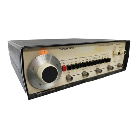
Wavetek
Wavetek 182A User manual
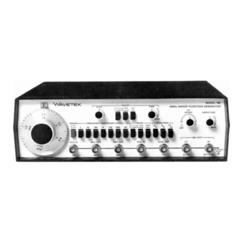
Wavetek
Wavetek 188 User manual
Wavetek
Wavetek 132 User manual
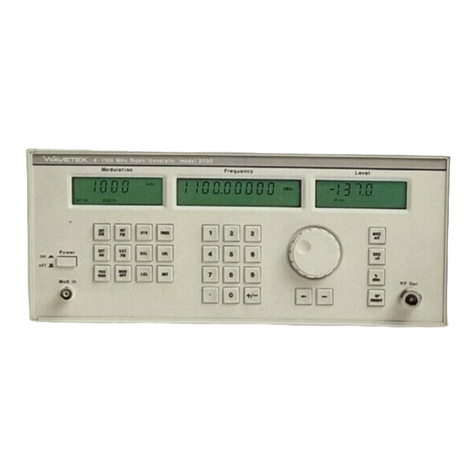
Wavetek
Wavetek 2500 User manual
Wavetek
Wavetek 182A User manual
Wavetek
Wavetek 144 User manual

Wavetek
Wavetek 132 User manual
Popular Portable Generator manuals by other brands

Daewoo
Daewoo DAIG Series user manual
Arvey
Arvey A1 User manual and warranty statement
HERON
HERON 8896431 Translation of the original user manual
Klein Tools
Klein Tools KTB1000 instruction manual
Bohmer-AG
Bohmer-AG W Series Operation manual
Brightwin Electronics
Brightwin Electronics BRT LB02G quick start guide

