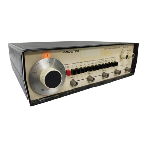
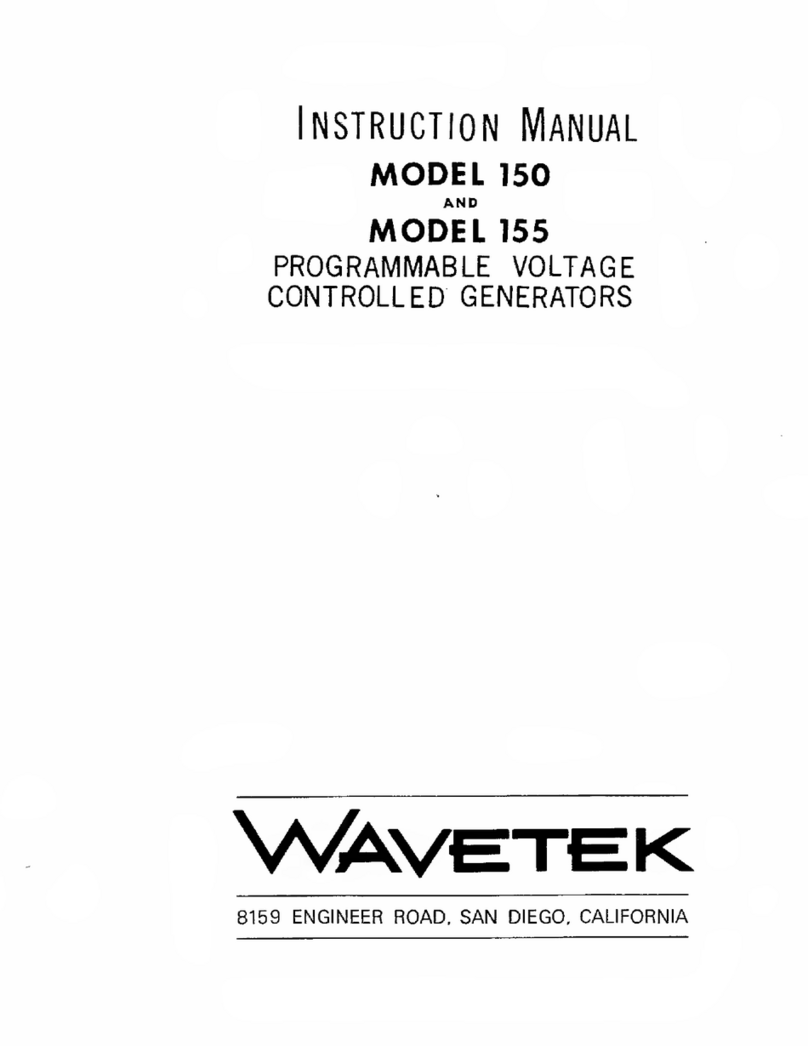
Wavetek 180 User manual

I
INSTRUCTION
MANUAL
MODELS
180
AND
180
LF
SWEEP/FUNCTION
GENERATORS
SWeEP-FUMCTiONGf^NLRATOR
180
St«F»:P«A!
E
on
OFFSET
FREQMULT^Hij
S^.EEPWIOTH
I
smi.c
PUISEOUT
iTTt
^
m
m
SWEEP/FUNCTION
GENERATOR
MODtc
jeotF
SWeiPRATE
DC
OFFSET
FRtQMUtT
iH*l
SWEEPWIDTH
\
f
Tj
\
r
/
WR<
AMPLtrUDE
PULSE
OUT
ITTL)
WVas/'

WARRANTY
All
Wavetek
instruments
are
warranteed
against
defects
in
material
and
workmanship
for
a
period
of
one
year
after
date
of
manufacture.
Wavetek
agrees
to
repair
or
replace
any
assembly
or
component
(except
batteries)
found
to
be
defective,
under
normal
use,
during
this
period.
Wavetek's
obligation
under
this
warranty
is
limited
solely
to
repairing
any
such
instrument
which
in
Wavetek's
sole
opinion
proves
to
be
defective
within
the
scope
of
the
warranty
when
returned
to
the
factory
or
to
an
authorized
service
center.
Transportation
to
the
factory
or
service
center
is
to
be
prepaid
by
purchaser.
Shipment
should
not
be
made
without
prior
authorization
by
Wavetek.
This
warranty
does
not
apply
to
any
products
repaired
or
altered
by
persons
not
authorized
by
Wavetek,
or
not
in
accordance
with
instructions
furnished
by
Wavetek.
If
the
instrument
is
defective
as
a
result
of
misuse,
improper
repair,
or
abnormal
conditions
or
operations,
repairs
will
be
billed
at
cost.
Wavetek
assumes
no
responsibility
for
its
product
being
used
in
a
hazardous
or
dangerous
manner
either
alone
or
in
conjunction
with
other
equipment.
High
voltage
used
in
some
instruments
may
be
dangerous
if
misused.
Special
disclaimers
apply
to
these
instruments.
Wavetek
assumes
no
liability
for
secondary
charges
or
consequential
damages
and,
in
any
event,
Wavetek's
liability
for
breach
of
warranty
under
any
contract
or
otherwise,
shall
not
exceed
the
purchase
price
of
the
specific
instrument
shipped
and
against
which
a
claim
is
made.
Any
recommendations
made
by
Wavetek
for
use
of
its
products
are
based
upon
tests
believed
to
be
reliable,
but
Wavetek
makes
no
warranty
of
the
results
to
be
obtained.
This
warranty
is
in
lieu
of
all
other
warranties,
expressed
or
implied,
and
no
representative
or
person
is
authorized
to
represent
or
assume
for
Wavetek
any
liability
in
connection
with
the
sale
of
our
products
other
than
set
forth
herein.

INSTRUCTION
MANUAL
MODELS
180
AND
180
LF
SWEEP/FUNCTION
GENERATORS
\\^\VETEK
Box
651,
San
Diego,
Calif.,
714-279-2200
3/77

CONTENTS
SECTION
1
GENERAL
DESCRIPTION
1.1
THE
MODELS
180
AND
180LF
1.2
SPECIFICATIONS
SECTION
2
INITIAL
PREPARATION
2.1
UNPACKING
INSPECTION
2.2
PREPARATION
FOR
USE
2.3
ELECTRICAL
ACCEPTANCE
CHECK
2.4
CHANGING
THE
OUTPUT
IMPEDANCE
.
..
.
SECTION
3
OPERATION
3.1
CONTROLS
AND
CONNECTORS
.
3.1.1
Power/Frequency
Controls
3.1.2
Amplitude
Controls
3.1.3
Function
Selections
3.1.4
Sweep
Controls
3.2
OPERATION
3.2.1
Signal
Termination
3.2.2
Manually
Controlled
Operation
3.2.3
Voltage
Controlled
Operation
3.2.4
Sweep
Generator
Operation
SECTION
4
CIRCUIT
DESCRIPTION
4.1
VOLTAGE
CONTROLLED
GENERATOR
(VCG)
4.2
FREQUENCY
CONTROL
4.3
WAVEFORM
OUTPUT
4.4
SWEEP
CIRCUITS
4.5
CRYSTAL
CONTROL
SECTION
5
CALIBRATION
5.1
FACTORY
REPAIR
5.2
REQUIRED
TEST
EQUIPMENT
5.3
REMOVING
GENERATOR
COVER
5.4
CALIBRATION
SECTION
6
TROUBLESHOOTING
6.1
FACTORY
REPAIR
6.2
TROUBLESHOOTING
CHART
6.3
TROUBLESHOOTING
INDIVIDUAL
COMPONENTS
SECTION?
PARTS
AND
SCHEMATICS
7.1
DRAWINGS
7.2
ORDERING
PARTS
7.3
ADDENDA
1-1
1-1
2-1
2-1
2-1
2-1
3-1
3-1
3-1
3-2
3-2
3-2
3-2
3-3
3-3
3-4
4-1
4-1
4-2
4-2
4-2
5-1
5-1
5-1
5-1
6-1
6-1
6-1
7-1
7-1
7-1

1
SECTION
GENERAL
DESCRiPTION
1.1
THE
MODELS
180
AND
180LF
The
Wavetek
Model
180
Sweep/Function
Generator
is
a
precision
source
of
sine,
triangle,
and
square
waveforms.
Frequency
of
the
waveforms
is
manually
and
remotely
variable
from
0.1
Hz
to
2
MHz.
The
generator
can
repeti
tively
sweep
from
one
frequency
to
a
higher
frequency,
with
controllable
rate
and
range
of
sweep.
Amplitude
of
the
waveforms
is
variable
from
10V
peak-to-peak
into
50f2
down
to
30
mV
p-p.
DC
reference
of
the
waveforms
can
be
offset
positively
and
negatively.
A
voltage
representing
generator
frequency,
a
fixed
amplitude
pulse
train
of
that
frequency,
and
a
voltage
ramp
representing
frequency
sweep
rate
are
provided
as
front
panel
outputs.
The
Wavetek
Model
180LF
(Low
Frequency)
Sweep/Func
tion
Generator
is
identical
to
the
Model
180
except
for
frequency
range:
0.01
Hz
to
200
kHz.
1.2
SPECIFICATIONS
The
specifications
(available
waveforms,
frequencies,
and
amplitudes),
operating
modes,
precision
(accuracy),
and
purity
(quality)
are
listed
in
the
following
paragraphs.
1.2.1
Versatility
Output
Signals
Sine
%
,
triangle
ramp
^
and
DC.
square
""Lj
,
TTL
pulse
J~L
Control
Generator
operates
in
continuous
and
sweep
modes.
Fre
quency
controlled
manually
or
with
external
voltage.
Frequency
Range
0.1
Hz
to
2
MHz
(180);
0.01
Hz
to
200
kHz
(180LF).
Operating
Frequency
Ranges
Model
180:
XI
0.1
Hz
to
2
Hz
X
10
0.1
Hz
to
20
Hz
X100
0.2
Hz
to
200
Hz
X
IK
2
Hz
to
2
kHz
XIOK
20
Hz
to
20
kHz
X
100K
200
Hz
to
200
kHz
X
1M
2
kHz
to
2
MHz
Model
180LF:
X.I
0.01
Hz
to
0.2
Hz
X
I
0.01
Hz
to
2
Hz
X
10
0.02
Hz
to
20
Hz
X100
0.2
Hz
to
200
Hz
X
IK
2
Hz
to
2
kHz
X10K
20
Hz
to
20
kHz
X
100K
200
Hz
to
200
kHz
Main
Output
Sine,
triangle
and
square
waveforms
and
DC
are
selectable.
HI
(0
dB)
and
LO
(-20
dS)
BNC
outputs
are
available
for
simultaneous
usage;
outputs
may
be
varied
to
HI
(—30dB)
and
LO
(—50
dB)
by
amplitude
control.
HI
output
provides
20V
peak-to-peak
max
open
circuit
(10V
peak-to-peak
max
into
50n
load).
LO
output
provides
IV
peak-to-peak
max
into
50n
load.
Both
output
impedances
are
50^2.
DC
Offset
and
DC
Output
DC
offset
of
waveform
and
DC
output
selectable
and
variable
through
HI
and
LO
BNC
outputs.
HI
output
±10V
max
(±5V
into
50n
load)
as
offset
or
Vdc
output.
LO
output
±1V
max
into
50n
load
as
offset
or
Vdc
output.
Waveform
offset
limited
to
±10
Vp
HI
and
±1
Vp
LO
(both
open
circuit
voltages).
Pulse
Output
TTL
pulse
(50%
duty
cycle)
at
generator
frequency.
Drives
up
to
20
TTL
loads.
GCV
Output
0
to
+2V
(nominal,
open
circuit)
proportional
to
frequency
of
main
generator.
Output
impedance
600J2.
VCG
—
Voltage
Controlled
Generator
Input
VCG
voltage
as
well
as
control
settings
select
generator
frequency.
Frequency
may
be
dc-programmed
or
ac-mod-
ulated
by
external
0
to
2V
signal.
Input
impedance
is
2
kS7.
VCG
input
can
change
generator
output
1000:1
on
all
ranges
except
X
10
Hz
and
X
1
Hz
ranges
(Model
180)
and
X
1
Hz
and
X
.1
Hz
(Model
180LF).
VCG
Input
Signal
Bandwidth;
100
kHz.
VCG
Slew
Rate:
O.IVZ/JS.
1-1

Sweep
Output
Ramp
waveform
output
with
5V
peak
into
open
circuit.
Output
impedance
600n.
1.2.2
Operating
Modes
Continuous
Operates
as
standard
VCG.
Frequency
of
main
generator
determined
by
dial/range
setting
and
VCG
input
voltage.
Sweep
Main
generator
is
frequency
modulated
by
internal
sweep
generator.
When
swept,
main
generator
frequency
rises
from
frequency
set
by
the
dial
and
range
setting
to
a
frequency
set
by
sweep
width
control.
Sweep
Rate:
30
ms
to
20s
(nominal)
continuously
adjustable
by
single
turn
control
on
front
panel.
Sweep
Width:
Up
to
1:1000
adjustable
on
all
ranges
except
X
1
Hz
and
X
10
Hz
ranges
(Model
180)
and
X
.1
Hz
and
X
1
Hz
(Model
180LF).
1.2.3 Horizontal
Precision
Dial
Accuracy
Model
180:
±3%
of
full
scale
for
0.1
Hz
to
2
MHz.
Model
180LF:
±3%
of
full
scale
for
0.01
Hz
to
200
kHz.
Time
Symmetry
Models
180
and
180LF,
as
applicable:
±1%
on
all
but
X
1M
range.
1.2.4
Vertical
Precision
Amplitude
Change
With
Frequency
(Sine)
Models
180
and
180LF,
as
applicable:
Less
than
±0.1
dB
on
all
ranges
thru
X
100K.
Less
than
±0.5
dB
on
X
1M
range.
1.2.5
Waveform
Purity
(Models
180
and
180LF,
as
applicable)
Sine
Distortion
Less
than
0.5%
on
X
100,
X
1K,
X
10K
ranges
(typically
0.2%).
Less
than
1.0%
on
X
1,
X
10,
X
TOOK
ranges
(typically
0.5%).
All
harmonics
30
dB
down
on
X
1M
range.
Square
Wave
Rise
and
Fall
Time
Less
than
75
nanoseconds.
Triangle
Linearity
Greater
than
99%
to
200
kHz.
1.2.6
Environmental
Specifications
apply
at
25°C
±5°C.
Instrument
will
operate
from
0°C
to
+50°C.
1.2.7
Mechanical
Dimensions
11%
in./28.6
cm
wide;
4
in./10.2
cm
high;
lOVa
in./26.7
cm
deep.
Weight
6.5
lb/2.9
kg
net;
9.5
lb/4.3
kg
shipping.
1.2.8
Power
105
to
125V
or
200
to
250V,
50
Hz
to
400
Hz.
Less
than
15
watts.
NOTE
AH
specifications
apply
when
frequency
dial
is
between
0.1
and
2.0,
amplitude
is
at
10V
p-p
and
output
is
from
HI
BNC
into
500.
load.
1-2

2
SECTION
INITIAL
PREPARATION
2.1
UNPACKING
INSPECTION
After
carefully
unpacking
the
instrument,
inspect
the
ex
ternal
parts
for
damage
to
knobs,
dials,
indicators,
surface
areas,
etc.
If
there
is
damage,
file
a
claim
with
the
carrier
who
transported
the
instrument.
Retain
the
shipping
con
tainer
and
packing
material
for
use
in
case
reshipment
is
required.
2.2
PREPARATION
FOR
USE
Before
connecting
the
instrument
to
line
power,
check
that
the
rear
panel
115/230V
switch
is
set
to
the
value
nearest
the
line
voltage
and
that
the
fuse
is
correct
for
the
switch
setting.
Check
that
the
plug
on
the
power
cord
is
the
mate
for
the
line
receptacle.
2.3
ELECTRICAL
ACCEPTANCE
CHECK
This
checkout
procedure
provides
a
general
verification
of
generator
operation.
Should
a
malfunction
be
found,
refer
to
the
Warranty
in
the
front
of
this
manual.
An
oscilloscope,
BOH
coax
cable,
and
a
50f2
feedthru
are
needed
for
this
procedure
(figure
2-1).
Preset
the
generator
front
panel
controls
as
follows:
Control
Position
FREQMULT
PWR
OFF
Frequency
Dial
l.Q
Function
AMPLITUDE
Full
clockwise
DC
OFFSET
OFF
SWEEPWIDTH
OFF
SWEEP
RATE
9
o'clock
Perform
the
steps
in
table
2-1;
monitor
the
50n
OUT
HI
connector
at
the
oscilloscope.
2.4
CHANGING
THE
OUTPUT
IMPEDANCE
The
output
impedance
is
normally:
HI
50n@10Vp-p
LO
50J2
@
1V
p-p
Attenuation
is
normally
0
-
30
dS.
Lowest
possible
ampli
tude
is
—50
dB.
If
simultaneous
BOOH
and
50n
output
impedances
are
desired:
MODEL
180
50L2„
LOAD
OUT®
Clh
OSCILLOSCOPE
Figure
2-1.
Acceptance
Check
Setup
1.
Change
value
of
R145
from
49912
to
604S2.
2.
Remove
R147.
The
result
is:
HI
5012
@
10V
p-p
LO
60012
@
10V
p-p
(low
power)
Attenuation
is
0
-
30
dB.
Lowest
possible
amplitude
is
—30
dB.
Square
wave
rise
and
fall
is
<
150
ns.
If
5012
and
any
other
impedance
greater
than
60012
are
desired,
replace
R145
with
resistor
of
that
value.
If
50
dB
of
attenuation
control
is
desired
in
a
modified
instrument,
change
R121
from
33.212
to
1.812.
Waveform
quality
above
20
kHz
will
be
considerably
impaired
at
-50
dB
compared
to
a
standard
instrument.
2-1

Table
2-1.
Acceptance
Check
Step
Control
Position/Operation
Observe
at
50SJ
OUT
1
FREQMULT
X
1
(Model
180)
X
.1
(Model
180LF)
1
Hz,
10V
p-p
sine
wave
(Model
180)
0.1
Hz,
10V
p-p
sine
wave
(Model
180LF)
2
FREQ
MULT
X
1,
X
10,
X
100,
- - -
X
1M
(as
applicable)
Frequency
increases
by
a
decade
for
every
change
of
switch
position
3
FREQ
MULT
X
IK
4
Function
Triangle
wave
5
Function
"b
Square
wave
6
AMPLITUDE
ccw
Decrease
in
waveform
amplitude
7
DC
OFFSET
cw
Positive
slew
of
waveform
from
full
negative
offset
8
DC
OFFSET
ccw
Negative
slew
of
waveform
g
DC
OFFSET
OFF
10
AMPLITUDE
Full
cw
11
Dial
Full
cw
12
SWEEP
WIDTH
Full
cw
Frequency
of
waveform
repetitively
sweeps
2-2

3
SECTION
OPERATiON
3.1
CONTROLS
AND
CONNECTORS
The
generator
front
panel
controls
and
connections
shown
in
figure
3-1
are
keyed
by
circled
numbers
to
the
following
descriptions.
3.1.1
Power/Frequency
Controls
(T)
FREQMULT/PWR
OFF
Power
is
turned
on
when
frequency
range
is
selected
at
the
FREQ
MULT
(Hz)
control.
The
ranges
multiplied
by
frequency
dial
settings
deter
mine
output
frequency.
The
frequency
dial
index
lights
when
power
is
turned
on.
(2)
Frequency
Dial
Frequency
dial
settings
multiplied
by
frequency
range
determine
output
frequency.
VCG
IN
Connector
Voltage
controlled
generator
input
(VCG
IN)
dc
excursions
proportionally
control
frequency
within
a
selected
range.
Positive
inputs
increase
frequencies
set
by
the
frequency
dial
and
range
control;
nega
tive
inputs
decrease
the
frequencies.
GCV
OUT
Connector
Generator
controlled
voltage
output
(GCV
OUT)
dc
excursions
of
OV
to
about
2V
proportionally
represent
output
frequency
within
a
given
range.
3.1.2
Amplitude
Controls
@
DC
OFFSET
Rotating
the
DC
OFFSET
control
clockwise
offsets
dc
center
reference
of
waveform
positive;
when
POWER/FREQUENCY
FREQ
UlTiH/t
SWEEP
WiOTH
SWEEP
AMPLITUDE
©
@
®
SWEEP/FUNCTION
a'VEEPRATE
DC
Of
\
^
iiv
F
\
/
OFF
\GCV
jTSiNeBP
PULSE
OUT
OUT
/
OUT
(TTLI
I
ENERATt
DEL
180
FUNCTIONS
Figure
3-1.
Model
180
Controls
and
Connectors
3-1

counterclockwise,
negative.
When
OFF,
the
wave
form
is
balanced
around
signal
ground
(figure
3-2).
TTL
PULSE
Figure
3-2.
Output
Waveforms
@
AMPLITUDE
Rotating
the
AMPLITUDE
control
fully
clockwise
provides
maximum
peak-to-peak
output
at
the
50n
OUT
connectors;
counterclockwise
for
up
to
30
dB
attenuation
of
output
amplitude.
50n
OUT
Connectors
Maximum
output
of
10V
p-p
signals
into
a
5012
load
(20V
p-p
open
circuit)
is
provided
at
the
50n
OUT
HI
connector,
and
20
dB
below
(1/10
or
a
1V
p-p
maximum)
of
that
level
at
the
5012
OUT
LO
connector.
3.1.3
Function
Selections
(D
%
Tj
,
and
DC
(Waveforms)
Sine
'V
,
triangle
'V
,
and
square
""L
wave
forms
are
selected
by
the
larger
of
the
two
concen
tric
controls;
the
DC
position
provides
a
dc
voltage
output
of
the
waveform
center
reference
level
at
the
5012
OUT
connectors.
@
TTL
PULSE
OUT
Connector
A
fixed
amplitude
Transistor-Transistor
Logic
(TTL)
square
pulse
train
of
the
output
frequency
is
provided
at
the
PULSE
OUT
(TTL)
connector.
(TTL
levels
are
OV
to
0.4V
for
a
logic
low
and
2.4V
to
5V
for
a
logic
high.)
The
output
can
drive
up
to
20
TTL
loads.
The
pulse
train
can
also
be
used
as
a
synchronizing
reference
for
the
main
output
@
.
Phase
of
the
waveforms
relative
to
the
TTL
pulse
is
shown
in
figure
3-2.
3.1.4
Sweep
Controls
@
SWEEP
WIDTH/OFF
Main
output
(at
5012
OUT
HI
or
LO)
frequency
sweep
is
turned
on
when
SWEEP
WIDTH
is
rotated
past
OFF.
Rotation
of
the
control
varies
the
peak
amplitude
of
an
internal
ramp
signal
(seen
at
GCV
OUT)
whose
voltage
controls
the
frequency
of
the
main
generator
(seen
at
5012
OUT).
See
figure
3-3.
.
SWEEP
TIME
GCV
OUT
5012
OUT
SWEEP
START
FREQUENCY
SET
BY
FREQUENCY
DIAL
SWEEP
WIDTH
SWEEP
STOP
FREQUENCY
SET
BY
SWEEP
WIDTH
Figure
3-3.
Effect
of
Sweep
on
Output
Frequency
SWEEP
OUT
Connector
The
sweep
generator
ramp
is
available
at
the
SWEEP
OUT
connector.
Amplitude
is
OV
to
5V
peak
(60012
source
impedance).
SWEEP
RATE
Rotation
of
SWEEP
RATE
controls
duration
of
the
sweep
voltage
ramp,
and
thus
frequency
of
sweep
repetition.
3.2
OPERATION
Operation
can
be
quite
varied
but
is
described
here
as
manual,
voltage
controlled
or
sweep
controlled.
The
gen
erator
is
ready
to
operate
as
soon
as
a
frequency
multiplier
is
selected;
however,
when
output
is
critical,
allow
Vi
hour
warm
up.
3.2.1
Signal
Termination
Proper
signal
termination,
or
loading,
of
the
generator
con
nectors
is
necessary
for
its
specified
operation.
For
example,
the
proper
termination
of
the
main
output
is
shown
in
figure
3-4.
Placing
the
50
ohm
terminator,
or
50
ohm
resistance,
in
parallel
with
a
higher
impedance,
matches
the
receiving
instrument
input
impedance
to
the
generator
3-2

output
impedance,
thereby
minimizing
signal
reflection
or
power
loss
on
the
line
due
to
impedance
mismatch.
MODEL
180
RECEIVING
INSTRUMENT
OUTPUT
IMPEDANCE
5on
OUTPUT
RG58
OR
EQUIVALENT
50r2
LOAD,
EFFECTIVE
CIRCUIT
RESISTANCE
-AAA^
1
1
(SIGNAL
LOAD)
V.
Figure
3-4.
Signal
Termination
The
input
and
output
impedances
of
the
generator
con
nectors
are
listed
below:
Connector
50S2
OUT
HI
50^2
OUT
LO
PULSE
OUT
(TTL)
SWEEP
OUT
VCG
IN
GCVOUT
Impedance
50^2
son
60on
2kn
60on
•The
PULSE
OUT
connector
can
drive
up
to
20
Transistor-Transistor
Logic
(TTL)
loads
(low
level
between
OV
and
0.4V.
and
high
level
between
2.4V
and
5V).
3.2.2
Manually
Controlled
Operation
For
basic
operation,
select
the
waveform
to
be
output,
and
set
the
output
signal
frequency
and
amplitude.
The
following
steps
demonstrate
manual
control
of
the
function
generator:
Step
Co
ntrol
/Co
n
nector
1
50n
OUT
2
FREQMULT
3
Frequency
Dial
4
Waveform
Selector
5
DC
OFFSET
6
AMPLITUDE
Setting
Connect
circuit
to
either
HI
or
LO
output
(Ref:
paragraph
3.2.1).
Set
to
desired
range
of
frequency.
Set
to
desired
frequency.
Set
to
desired
waveform.
See
figure
3-5.
Select
desired
amplitude.
TRIANGLE
WAVEFORM
FROM
HI
OUTPUT
INTO
50I2
load
•f6V
OV
-5V
GDC
OFFSET
POSITIVE
DC
OFFSET
NEGATIVE
DC
OFFSET
+5V
—
n—
EXCESSIVE
POSITIVE
OFFSET
OR
LOADING
EXCESSIVE
NEGATIVE
OFFSET
OR
LOADING
Figure
3-5.
DC
OFFSET
Control
3.2.3
Voltage
Controlled
Operation
Operation
as
a
voltage
controlled
function
generator
(VCG)
is
as
for
a
manually
controlled
function
generator,
only
the
frequency
within
particular
ranges
is
additionally
controlled
with
dc
levels
(±2V
excursions)
injected
at
the
VCG
IN
connector.
Perform
the
steps
given
in
paragraph
3.2.2,
only
set
the
frequency
dial
to
determine
a
reference
from
which
the
frequency
is
to
be
voltage
controlled:
1.
For
frequency
control
with
positive
dc
inputs
at
VCG
IN,
set
the
dial
for
a
lower
frequency
limit.
2.
For
frequency
control
with
negative
dc
inputs
at
VCG
IN,
set
the
dial
for
an
upper
frequency
limit.
3.
For
modulation
with
an
ac
input
at
VCG
IN,
center
the
dial
at
the
desired
center
frequency.
Do
not
exceed
the
maximum
dynamic
range
of
the
selected
frequency
range.
Figure
3-6
is
a
nomograph
with
examples
of
the
frequency
dial
effect
as
a
reference
for
VCG
IN
voltages.
Example
1
shows
that
with
OV
VCG
input,
frequency
is
as
determined
by
the
main
dial
setting,
1.0
in
this
example.
Example
2
shows
that
with
a
positive
VCG
input,
output
frequency
is
increased.
Examples
shows
that
with
a
negative
VCG
input,
output
frequency
is
decreased.
(Note
that
the
50S2
OUT
Frequency
Factor
column
value
must
be
multiplied
by
a
frequency
range
multiplier
to
give
the
actual
50^2
OUT
frequency.)
3-3

MAIN
DIAL
SETTING
2.0
1.8-f-
1.6
1.4
1.2--
1.0
.8--
.6
.4
.2
.002-'-
VCG
IN
VOLTAGE
-2.0-|-
-1.6
-
-
-1.2--
-
.8
-
.4^
^
,
EXAMPLE
1
X
U-t-
\
+
.4--
\
+1.2-
S-?!.
son
OUT
FREQUENCY
FACTOR
-.002
-.2
-.4
-.6
-.8
-1.0
--1.2
-1.4
-1.6
+1.6-1-
\
\
-1.8
-2.0
+2.0-'-
Figure
3-6.
VCG
Voltage-to-Frequency
Nomograph
The
up
to
1000:1
VCG
sweep
of
the
generator
frequencies
available
in
each
range
results
from
a
2V
excursion
at
the
VCG
IN
connector.
With
the
frequency
dial
set
to
2.0,
excursions
between
—2V
and
OV
at
VCG
IN
provide
the
up
to
1000:1
frequency
sweep.
With
the
dial
set
to
.002,
excursions
between
OV
and
+2V
at
VCG
IN
provide
the
up
to
1000:1
sweep
within
the
set
frequency
range.
3.2.4
Sweep
Generator
Operation
Operation
as
a
sweep
generator
is
like
operation
as
a
manual
function
generator,
only
the
frequency
is
automatically
and
repetitively
swept
from
the
set
frequency
to
a
higher
fre
quency.
Actually,
an
internally
generated
positive-going
voltage
ramp
{available
at
the
SWEEP
OUT
connector)
can
be
modified
in
amplitude
and
used
like
a
VCG
input
voltage
to
sweep
the
output
frequency
(see
figure
3-3).
Perform
the
steps
in
paragraph
3.2.1
and
the
following
steps
for
use
as
a
sweep
generator:
Step
Control/Connector
SWEEP
WIDTH
SWEEP
RATE
Setting
As
desired.
This
determines
the
upper
frequency
of
the
sweep.
As
desired.
This
determines
the
speed
of
the
sweep.
NOTE
NOTE
Nonlinear
operation
results
when
the
VCG
input
voltage
is
excessive;
that
is,
when
the
attempted
generator
frequency
exceeds
the
range
setting
(2
times
the
multiplier
setting)
or
in
the
other
direction,
1/1000th
of
the
range
setting.
To
monitor
the
ramp
generator,
use
the
SWEEP
OUT
connector.
To
monitor
the
frequency
of
the
main
generator,
use
the
GCV
OUT
connector,
which
is
a
voltage
proportional
to
the
generator
frequency.
3-4

4
SECTION
CIRCUIT
DESCRIPTION
4.1
VOLTAGE
CONTROLLED
GENERATOR
(VCG)
As
shown
in
figure
4-1,
the
VCG
summing
amplifier
sums
the
currents
from
the
frequency
dial,
sweep
generator,
crystal
control
and
VCG
input
connector.
The
VCG
sum
ming
amplifier
is
an
inverting
amplifier
whose
output
current
is
used
to
control
a
positive
current
source
and
a
negative
current
source.
The
currents
from
the
two
current
sources
are
equal
and
opposite
polarity
and
the
magnitudes
are
directly
proportional
to
the
current
of
the
VCG
sum
ming
amplifier
output.
The
diode
gate,
which
is
controlled
by
the
hysteresis
switch.
Is
used
to
switch
the
positive
current
or
the
negative
current
to
the
integrating
capacitor
selected
by
the
frequency
multiplier.
If
the
positive
current
is
switched
into
the
capacitor,
the
voltage
across
the
capacitor
will
increase
linearly
to
generate
the
positive
slope
of
the
triangle
wave.
If
the
current
is
negative,
the
voltage
across
the
capacitor
will
decrease
linearly
to
produce
the
negative
slope.
0,
HYSTERESIS
SWITCH
BUFFER^
The
triangle
buffer
amplifier
is
a
unity
gain
amplifier
whose
output
is
fed
to
the
hysteresis
switch
as
well
as
to
the
sine
converter.
The
hysteresis
switch
has
two
voltage
limit
points
(+1.25V
and
—1.25V).
(See
figure
4-2.)
During
the
time
the
output
voltage
of
the
triangle
buffer
amplifier
is
increasing,
the
output
voltage
of
the
hysteresis
switch
is
positive,
but
when
the
output
voltage
of
the
triangle
amplifier
reaches
+1.25V,
it
triggers
the
hysteresis
switch
causing
the
switch
output
to
become
negative.
Once
the
control
voltage
into
the
diode
gate
becomes
negative,
it
will
switch
the
positive
current
out
and
switch
the
negative
current
in
to
the
integrating
capacitor,
starting
a
linear
decrease
of
the
voltage
across
the
capacitor.
When
the
decreasing
voltage
reaches
-1.25V,
the
output
of
the
hys
teresis
switch
will
switch
back
to
positive,
reversing
the
process.
This
action
generates
the
triangle
waveform
as
shown
in
figure
4-2.
Since
the
output
of
the
hysteresis
switch
isa
square
wave,
the
result
is
simultaneous
generation
of
a
square
wave
and
triangle
wave
at
the
same
frequency.
4.2
FREQUENCY
CONTROL
The
output
frequency
is
determined
by
the
magnitude
of
the
integrating
capacitor
selected
by
the
frequency
multiplier
and
the
magnitude
of
the
positive
and
negative
current
sources
(figure
4-1).
Since
the
current
magnitudes
are
linearly
proportional
to
the
sum
of
the
VCG
current,
the
output
frequency
will
also
be
linearly
proportional
to
the
current
sum.
ni-
+1.25V
-1.25
V
wv
^0.91
SQUARE
WAVE
TRIANGLE
B
WAVE
Figure
4-2.
Simplified
Timing
Diagram
Figure
4-3.
Current
Divider
4-1

By
using
current
division,
the
magnitude
of
the
capacitor
is
effectively
increased,
allowing
the
generation
of
lower
fre
quencies.
Figure
4-3
is
the
simplified
diagram
showing
current
divider
operation.
By
reducing
integration
current
precisely
by
a
factor
of
10
while
holding
triangle
wave
amplitude
constant,
it
is
possible
to
extend
the
lower
fre
quency
range
by
a
factor
of
10
with
fixed
capacitance
C.
Since
points
A
and
B
are
at
the
equipotential
points,
constant
current
output
I
can
be
divided
by
resistance
ratio
of
R
and
9R.
Then,
Integration
current
of
capacitor
C
is
reduced
to
0.1
I.
The
lower
current
extends
the
frequency
range
of
the
function
generator
by
a
factor
of
10.
The
same
theory
is
applied
to
extend
the
frequency
range
by
a
factor
of
100.
4.3
WAVEFORM
OUTPUT
The
inverted
output
of
the
hysteresis
switch
is
fed
to
the
TTL
buffer
amplifier
and
also
the
square
wave
shaper
(figure
4-1).
The
square
wave
shaper
consists
of
a
shaping
circuit
which
limits
the
output
swing
to
±1.25
volts.
The
output
signal
from
the
triangle
buffer
amplifier
is
applied
to
the
sine
converter,
which
uses
a
diode-resistor
network
with
linear
sections
to
shape
a
sine
wave.
The
sine,
triangle
or
square
waveform
is
fed
to
the
summing
amplifier
through
the
waveform
selector
switch.
The
output
of
summing
amplifier
is
fed
through
the
amplitude
control
to
the
output
amplifier.
The
output
amplifier
is
an
inverting
amplifier
whose
output
is
capable
of
driving
10V
p-p
into
son
load
from
50n
source
impedance.
4.4
SWEEP
CIRCUITS
Sweep
rate
control
determines
the
amount
of
integrating
current
fed
to
the
positive
input
of
the
sweep
integrator
(figure
4-1).
The
output
voltage
increases
linearly
as
the
sweep
circuit
capacitor
is
charged
to
form
the
positive
slope
of
the
ramp.
As
the
ramp
output
reaches
the
preset
level
of
+5V,
the
peak
detector
turns
on
while
the
positive
feedback
circuit
holds
the
positive
output
state.
The
large
flyback
current
Ip
is
fed
to
the
negative
input
of
the
sweep
integra
tor
while
overcoming
minute
integrating
current
Ir.
Thus,
the
ramp
output
decreases
rapidly
toward
the
negative
voltage,
forming
the
negative
slope
of
the
ramp.
When
the
negative
slope
reaches
zero
volts,
the
zero
detector
turns
on,
the
peak
detector
is
unlatched
and
the
flyback
current
source
is
turned
off,
allowing
the
output
voltage
to
increase
linearly.
4-2

5
SECTION
CALIBRATION
I
5.1
FACTORY
REPAIR
Wavetek
maintains
a
factory
repair
department
for
those
customers
not
possessing
the
necessary
personnel
or
test
equipment
to
maintain
the
instrument.
If
an
instrument
is
returned
to
the
factory
for
calibration
or
repair,
a
detailed
description
of
the
specific
problem
should
be
attached
to
minimize
turnaround
time.
5.2
REQUIRED
TEST
EQUIPMENT
Voltmeter
Distortion
Analyzer
Oscilloscope
50n
(±0.1%)
Load
Counter
(6
digit)
5.3
REMOVING
GENERATOR
COVER
Remove
the
four
screws
in
the
lower
cover,
place
the
instrument
on
its
feet
and
lift
off
the
top
cover.
5.4
CALIBRATION
After
referring
to
the
following
preliminary
data,
perform
calibration,
as
necessary,
per
table
5-1.
If
performing
partial
calibration,
check
previous
settings
and
adjustments
for
applicability.
1.
Unless
otherwise
noted,
all
measurements
made
at
the
50n
OUT
connector
should
be
terminated
Into
a
50n
«1%,
1W)
load.
2.
Before
connecting
the
unit
to
an
ac
source,
check
the
ac
line
circuit
to
make
sure
the
115/230
volt
switch
is
set
at
the
correct
position
(see
paragraph
2.2).
3.
Start
the
calibration
by
setting
the
front
panel
switches
as
follows:
Dial
2.0
FREQMULT
X
IK
SWEEPWIDTH
OFF
SWEEP
RATE
ccw
DC
OFFSET
OFF
Function
\
AMPLITUDE
cw
4.
Allow
the
unit
to
warm
up
at
least
30
minutes
for
final
calibration.
Table
5-1.
Calibration
Chart
Step
Check
Tester
Gal
Points
Control
Setting
Adjust
Desired
Results
Remarks
1
Power
supply
regulation
Voltmeter
TP2
(TPl
ground)
R9
+15±0.01V
2
TP3
-15±0.05V
3
Distortion
Distortion
analyzer
(50fi
terminated)
5on
OUT
HI
R78
R103
Minimum
distortion
5-1

Table
5-1.
Calibration
Chart
(Continued)
Step
Check
Tester
Gal
Points
Control
Setting
Adjust
Desired
Results
Remarks
4
VCG
null
Scope
(50n
terminated)
FREQIVIULTX
100K
Function
""L
Dial
full
cw
Scope
vert
2V/div
Scope
horiz
.5
ms/div
R43
Minimum
fre
quency
shift
Adjust
generator
dial
for
1
full
square
on
scope.
Alternately
short
and
open
VCG
IN
BNC
while
adjust
ing
R43.
5
Horizontal
symmetry
Scope
X
10
on
R47
Maximum
sym
metry
Alternately
switch
scope
triggering
from
positive
to
negative
slope
while
adjusting
R47.
6
Dial
0.1
FREQMULTX
10
Scope
sweep
O.ls/div
DC
triggering
R66
Maximum
sym
metry
For
180LF,
FREQ
MULT
X
1.
Scope
sweep
Is/div.
7
Frequency
accuracy
Counter
(5012
terminated)
Dial
2.0
FREQ
MULT
X
1
thru
X
10K
R39
Best
frequency
accuracy
over
X
1
thru
X
10K
8
FREQMULT
X
1M
Function
\
\
^
C19
Best
frequency
accuracy
for
all
waveforms
9
DC
level
Voltmeter
(5012
terminated)
FREQMULT
X
IK
Function
DC
Amplitude
ccw
R125
0
±20
mVdc
1
5-2

6
SECTION
TROUBLESHGOTiNG
6.1
FACTORY
REPAIR
Wavetek
maintains
a
factory
repair
department
for
those
customers
not
possessing
the
necessary
personnel
or
test
equipment
to
maintain
the
instrument.
If
an
inistrument
is
returned
to
the
factory
for
calibration
or
repair,
a
detailed
description
of
the
specific
problem
should
be
attached
to
minimize
turnaround
time.
6.2
TROUBLESHOOTING
CHART
Troubleshooting
charts
are
given
in
figure
6-1.
The
charts
do
not
cover
every
possible
trouble,
but
will
be
an
aid
In
systematically
isolating
faulty
components.
6.3
TROUBLESHOOTING
INDIVIDUAL
COMPONENTS
6.3.1
Transistor
1.
A
transistor
is
defective
if
more
than
one
volt
is
mea
sured
across
its
base
emitter
junction
in
the
forward
direction.
2.
A
transistor
when
used
as
a
switch
may
have
a
few
volts
reverse
bias
voltage.
3.
If
the
collector
and
emitter
voltages
are
the
same,
but
the
base
emitter
voltage
is
less
than
500
mV
forward
voltage
(or
reversed
bias),
the
transistor
is
defective.
4.
A
transistor
is
defective
if
its
base
current
is
larger
than
10%
of
its
emitter
current
(calculate
currents
from
voltage
across
the
base
and
emitter
series
resistors).
In
a
transistor
differential
pair
(common
emitter
stages),
either
their
base
voltages
are
the
same
in
normal
operating
condition,
or
the
one
with
less
forward
voltage
across
its
base
emitter
junction
should
be
off
(no
collector
current);
otherwise,
one
of
the
transistors
is
defective.
6.3.2
Diode
1.
A
diode
is
defective
if
there
is
greater
than
one
volt
(typically
0.7
volt)
forward
voltage
across
it.
6.3.3
Operational
Amplifier
(e.g.,
UA741C,
LM318)
1.
The
"+"
and
"
inputs
of
an
operational
amplifier
will
have
less
than
15
mV
voltage
difference
when
operating
under
normal
conditions.
2.
If
the
output
voltage
stays
at
maximum
positive,
its
"+"
input
voltage
should
be
more
positive
than
its
"
input
voltage,
or
vice
versa;
otherwise,
the
operational
amplifier
is
defective.
6.3.4
Capacitor
1.
Shorted
capacitors
have
zero
volts
across
their
termi
nals.
2.
Opened
capacitor
can
be
located
(but
not
always)
by
using
a
good
capacitor
connected
in
parallel
with
the
capacitor
under
test
and
observing
the
resulting
effect.

SYSTEM
CHECK
50^2
OUT
BAD
1
f
TURN
DC
OFFSET
&
SWEEP
OFF
ALL
FUNCTIONS
BAD
V
GOOD
'V
BAD
\good
Ti
BAD
YES
r
SELECT
APR
R
OX
±2v
nL
AT
JUNCTION
^
CR20,22
APPROX
±1V
\
AT
R119
WIPER
WITH
AMPLITUDE
CW
?
PPRO
GO
TO
GENERATOR
LOOP
CHECK
CHECK
SW2
A
&
B
&
IC10CKT
REMOVE
R120
APPROX
±1V
\
SET
WAVEFORM
TO
L
CHECK
CR20
-
23
&
SW2
A
&
B
AT
JUNCTION
CR21,
23
OK
?
CHECK
CR20-
23
&
021
CKT
CHECK
023
-
29
CIRCUIT
REINSTALL
R120;
^
NO,
CHECK
R119
WITH
AMPLITUDE
CW
?
REINSTALL
Figure
6-1.
Troubleshooting
Chart
(Sheet
1
of
4)
6-2

GENERATOR
LOOP
CHECK
NO
±1.25V
'V
AT
PIN
6
106
REGULATED
<+
&
-
15
Vdc
AT
TP2
&
TP3
115/220V
SWITCH
&
POWER
CONNECTION
'
OK
?
+24
Vdc
ON
C2
(+)
8,^-24
Vdc
ON
C1
(-)
YES
GO
TO
POWER
SUPPLY
REGULATOR
CHECK
DIODES
CRl
-4
OK
YES
CHECK
XFMR
<
ROTATE
DIAL
FROM
TOP
TO
BOTTOM;
+15V
T0~15
mV
SHIFT
AT
E6
r
WIRING
E5
-7
OK
YES
DIAL
POTENTIO
METER
BAD
<
<
ROTATE
DIAL;
0
Vdc
WITH
NO
SHIFT
AT
PIN
3IC4
^ES
ROTATE
DIAL;
APPROX
-15V
TO
lOV
SHIFT
AT
PINS7.4,2
&
+15V
TO
+10V
SHIFT
AT
PINS
10,13
IC5
?
^^ES
^±2
Vdc
ATJUNCTION
&
--+1.25
Vdc*
AT
JUNCTION
CR11.CR13
?
PROBLEM
IN
IC4
CIRCUIT
&
PNP
AT
PINS?
ICS
OK
PROBLEM
IN
ICS
CIRCUIT
CHECK
018
•
20
CR14,
15
&
IC7
CIRCUIT
CR10-
13
&
SW1
A,
B,C
OK
SAME
Vdc
AT
PINS
3,
8
ICS
ICS
CIRCUIT
OK
+1.25
Vdc
AT
PIN
8
ICS
CHECK
GIB
-
20,
CR14,
15
&
IC7
CIRCUIT
YES
CHECK
CR14,
15
THE
TOP
OR
BOTTOM
OF
THE
SQUARE
AND
TRIANGLE
WAVEFORMS.WHICH
INDICATES
A
LOCKED
UP
GENERATOR
Figure
6-1.
Troubleshooting
Chart
(Sheet
2
of
4)
6-3

POWER
SUPPLY
REGULATOR
CHECK
^NO
REGULATED
+
&^
-IBVdc
AT
TP2
8<TP3;
V
FUSE
OK
y
UYES
+15
Vdc
REG
NEAR
OV
YES
NO
YES
NO
+15
Vdc
REGULATOR
IS
ASSUMED
TO
BE
IN
CURRENT-LIMIT
MODE
-15
Vdc
REG
NEAR
OV
+15
Vdc
REGULATOR
IS
ASSUMED
TO
BE
DEFECTIVE
YES
NO
-15
Vdc
REGULATOR
IS
ASSUMED
TO
BE
IN
CURRENT-LIMIT
MODE
R1
&
03
OK
-15
Vdc
REGULATOR
IS
ASSUMED
TO
BE
DEFECTIVE
YES
YES
R13
&
07
OK
YES
05
-8
&
iC2
CKT
OK
YES
"-24
Vdc
UNREGULATED
\
GOOD
/
+15
Vdc
^
PARTIALLY
REGULATED
'^1
•
4>
CR5
&
IC1
CKT
OK
ISOLATE
LOW
Z
BY
LIFTING
+15V
JUMPERS
ISOLATE
LOW
Z
BY
LIFTING
-15V
JUMPERS
Figure
6-1.
Troubleshooting
Chart
(Sheet
3
of
4)
6-4
This manual suits for next models
1
Table of contents
Other Wavetek Portable Generator manuals
Wavetek
Wavetek 1370 Installation instructions

Wavetek
Wavetek 1001A User manual

Wavetek
Wavetek 148A User manual

Wavetek
Wavetek 144 User manual

Wavetek
Wavetek 188 User manual

Wavetek
Wavetek 188 User manual

Wavetek
Wavetek 150 User manual

Wavetek
Wavetek FG3B User manual

Wavetek
Wavetek 182A User manual
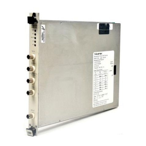
Wavetek
Wavetek 182A User manual