Wavetek ANT-20 User manual


Please direct all enquiries to your
local Wavetek Wandel Goltermann sales
company. The addresses are given at the
end of this handbook.
Copyrights
This product orparts of it are based upon
Recommendations and/or Standards of the
Standardization Sector of the International
Telecommunication Union- ITU-T and/or of the
European Telecommunications Standards Institute -
ETSI. These Recommendations and Standards are
subject to copyrights of these organizations. Without
written permission of the ITU-T and/or ETSI it isnot
permitted to copy ITU-T Recommendations or ETSI
standards or parts thereof and/or make them available
to third parties.
Wavetek Wandel Goltermann
Eningen GmbH & Co.
Mühleweg 5, 72800 Eningen u. A.
© 2000
Author: MDD/TD
Translator: JohnNutley
Order no.: 3035/98.36
Edition: 05/00.07(V 7.20)
Previous Edition:
04/00.04(V7.1)
Subject to change without notice.
Our normal guarantee and delivery
terms apply.
Printed in Germany

ANT-20/ANT-20E Concatenation Options
i
Contents
Introduction
1 Concatenation options. . . . . . . . . . . . . . . . . . . . . . . . . . . . . . . . . . . . .I-1
1.1 OC-12c/STM-4c options . . . . . . . . . . . . . . . . . . . . . . . . . . . . .I-1
1.2 OC-48c/STM-16c options . . . . . . . . . . . . . . . . . . . . . . . . . . . .I-2
2 Applications . . . . . . . . . . . . . . . . . . . . . . . . . . . . . . . . . . . . . . . . . . . . .I-3
2.1 OC-12c/STM-4c . . . . . . . . . . . . . . . . . . . . . . . . . . . . . . . . . . .I-3
2.1.1 OC-12c/STM-4c TEST ERROR (BULK);
(Contiguous Concatenation Mapping). . . . . . . . . . . . . . . . . . .I-4
2.1.2 OC-12c/STM-4c ATM TESTING
(Contiguous Concatenation Mapping). . . . . . . . . . . . . . . . . . .I-5
2.1.3 OC-12v/STM-4v VIRTUAL CONCATENATION
(Virtual Concatenation Mapping). . . . . . . . . . . . . . . . . . . . . . .I-5
2.2 OC-48c/STM-16c . . . . . . . . . . . . . . . . . . . . . . . . . . . . . . . . . .I-6
2.2.1 OC-48c/STM-16c ERROR TEST (BULK);
(Contiguous Concatenation Mapping). . . . . . . . . . . . . . . . . . .I-8
2.2.2 OC-12c/STM-4c ERROR TEST (BULK);
(Contiguous Concatenation Mapping). . . . . . . . . . . . . . . . . . .I-8
2.2.3 OC-12c/STM-4c ATM TESTING
(Contiguous Concatenation Mapping). . . . . . . . . . . . . . . . . . .I-9
3 Operation. . . . . . . . . . . . . . . . . . . . . . . . . . . . . . . . . . . . . . . . . . . . . . .I-10
Specifications OC-12c/STM-4c
1 Generator section. . . . . . . . . . . . . . . . . . . . . . . . . . . . . . . . . . . . . . . .S-1
1.1 Digital signal output. . . . . . . . . . . . . . . . . . . . . . . . . . . . . . . .S-1
1.1.1 Signal output [18], optical . . . . . . . . . . . . . . . . . . . . . . . . . . .S-1
1.2 Clock generation and bit rates. . . . . . . . . . . . . . . . . . . . . . . .S-2
1.2.1 Clock generation . . . . . . . . . . . . . . . . . . . . . . . . . . . . . . . . . .S-2
1.2.2 Bit rate. . . . . . . . . . . . . . . . . . . . . . . . . . . . . . . . . . . . . . . . . .S-2
1.3 SDH and SONET Tx signals. . . . . . . . . . . . . . . . . . . . . . . . .S-2
1.3.1 OC-12c/STM-4c Tx signal. . . . . . . . . . . . . . . . . . . . . . . . . . .S-2
1.3.2 Scrambling . . . . . . . . . . . . . . . . . . . . . . . . . . . . . . . . . . . . . .S-2
1.3.3 Overhead generation. . . . . . . . . . . . . . . . . . . . . . . . . . . . . . .S-3
1.3.3.1 Section overhead (SOH), Transport overhead (TOH). . . . . .S-3

Concatenation Options ANT-20/ANT-20E
ii
1.3.4 VC-4c path overhead (POH), high-order . . . . . . . . . . . . . . . S-4
1.3.4.1 Contiguous concatenation (VC-4-4c) . . . . . . . . . . . . . . . . . . S-4
1.3.4.2 Virtual concatenation (VC-4-4v) . . . . . . . . . . . . . . . . . . . . . . S-5
1.3.5 Generation of pointer actions . . . . . . . . . . . . . . . . . . . . . . . . S-5
1.3.5.1 Contiguous concatenation . . . . . . . . . . . . . . . . . . . . . . . . . . S-5
1.3.5.2 Virtual concatenation . . . . . . . . . . . . . . . . . . . . . . . . . . . . . . S-6
1.3.6 OC-12c/STM-4c anomaly insertion. . . . . . . . . . . . . . . . . . . . S-7
1.3.7 OC-12c/STM-4c defect generation. . . . . . . . . . . . . . . . . . . . S-9
1.4 Payload generation. . . . . . . . . . . . . . . . . . . . . . . . . . . . . . . S-10
1.4.1 BULK signal generator . . . . . . . . . . . . . . . . . . . . . . . . . . . . S-10
1.4.1.1 Payload. . . . . . . . . . . . . . . . . . . . . . . . . . . . . . . . . . . . . . . . S-10
1.4.1.2 Bit patterns . . . . . . . . . . . . . . . . . . . . . . . . . . . . . . . . . . . . . S-10
1.4.1.3 Anomaly insertion . . . . . . . . . . . . . . . . . . . . . . . . . . . . . . . . S-10
1.4.2 ATM generator section . . . . . . . . . . . . . . . . . . . . . . . . . . . . S-11
1.4.2.1 Scrambling . . . . . . . . . . . . . . . . . . . . . . . . . . . . . . . . . . . . . S-11
1.4.2.2 Anomaly insertion . . . . . . . . . . . . . . . . . . . . . . . . . . . . . . . . S-11
1.4.2.3 Defect generation . . . . . . . . . . . . . . . . . . . . . . . . . . . . . . . . S-12
1.4.2.4 Test channel . . . . . . . . . . . . . . . . . . . . . . . . . . . . . . . . . . . . S-12
1.4.2.5 Background load. . . . . . . . . . . . . . . . . . . . . . . . . . . . . . . . . S-13
1.4.2.6 Fill cells. . . . . . . . . . . . . . . . . . . . . . . . . . . . . . . . . . . . . . . . S-13
1.4.2.7 AAL-1 segmentation . . . . . . . . . . . . . . . . . . . . . . . . . . . . . . S-13
2 Receiver section. . . . . . . . . . . . . . . . . . . . . . . . . . . . . . . . . . . . . . . . S-14
2.1 Digital signal inputs. . . . . . . . . . . . . . . . . . . . . . . . . . . . . . . S-14
2.1.1 Signal input [17], optical . . . . . . . . . . . . . . . . . . . . . . . . . . . S-14
2.1.2 Signal input [16], electrical . . . . . . . . . . . . . . . . . . . . . . . . . S-15
2.1.3 Clock recovery . . . . . . . . . . . . . . . . . . . . . . . . . . . . . . . . . . S-15
2.2 SDH and SONET Rx signals . . . . . . . . . . . . . . . . . . . . . . . S-15
2.2.1 OC-12c/STM-4c Rx signal . . . . . . . . . . . . . . . . . . . . . . . . . S-15
2.2.2 Descrambling . . . . . . . . . . . . . . . . . . . . . . . . . . . . . . . . . . . S-15
2.3 Measurement modes . . . . . . . . . . . . . . . . . . . . . . . . . . . . . S-16
2.3.1 Evaluation of section overhead (SOH),
transport overhead (TOH). . . . . . . . . . . . . . . . . . . . . . . . . . S-16
2.3.2 Evaluation of path overhead (POH) . . . . . . . . . . . . . . . . . . S-16
2.3.2.1 Contiguous concatenation . . . . . . . . . . . . . . . . . . . . . . . . . S-16
2.3.2.2 Virtual concatenation . . . . . . . . . . . . . . . . . . . . . . . . . . . . . S-17
2.3.3 Measurement of AU pointer actions . . . . . . . . . . . . . . . . . . S-17
2.3.4 Anomaly measurements. . . . . . . . . . . . . . . . . . . . . . . . . . . S-18

ANT-20/ANT-20E Concatenation Options
iii
2.3.5 Defect detection . . . . . . . . . . . . . . . . . . . . . . . . . . . . . . . . . S-19
2.4 Payload . . . . . . . . . . . . . . . . . . . . . . . . . . . . . . . . . . . . . . . .S-21
2.4.1 BULK signal receiver. . . . . . . . . . . . . . . . . . . . . . . . . . . . . .S-21
2.4.1.1 Bit pattern payloads. . . . . . . . . . . . . . . . . . . . . . . . . . . . . . .S-21
2.4.1.2 Anomaly measurements . . . . . . . . . . . . . . . . . . . . . . . . . . .S-21
2.4.1.3 Defect detection . . . . . . . . . . . . . . . . . . . . . . . . . . . . . . . . .S-21
2.4.2 ATM receiver section. . . . . . . . . . . . . . . . . . . . . . . . . . . . . .S-21
2.4.2.1 Descrambling . . . . . . . . . . . . . . . . . . . . . . . . . . . . . . . . . . .S-21
2.4.2.2 Measurement modes. . . . . . . . . . . . . . . . . . . . . . . . . . . . . .S-22
2.4.2.3 Anomaly measurements . . . . . . . . . . . . . . . . . . . . . . . . . . .S-22
2.4.2.4 Defect detection . . . . . . . . . . . . . . . . . . . . . . . . . . . . . . . . .S-22
2.4.2.5 ATM performance measurements. . . . . . . . . . . . . . . . . . . .S-23
2.4.3 User channel analysis and load measurement . . . . . . . . . .S-23
2.4.3.1 AAL-1 reassembly. . . . . . . . . . . . . . . . . . . . . . . . . . . . . . . .S-25
Specifications OC-48c/STM-16c
1 Generator section. . . . . . . . . . . . . . . . . . . . . . . . . . . . . . . . . . . . . . . S-27
1.1 Digital signal output. . . . . . . . . . . . . . . . . . . . . . . . . . . . . . .S-27
1.1.1 Signal output [47], optical . . . . . . . . . . . . . . . . . . . . . . . . . .S-27
1.1.2 Signal output [46], electrical . . . . . . . . . . . . . . . . . . . . . . . .S-28
1.2 Clock generator and bit rates . . . . . . . . . . . . . . . . . . . . . . .S-28
1.2.1 Clock generation internal. . . . . . . . . . . . . . . . . . . . . . . . . . .S-28
1.2.2 Clock generation external [45]. . . . . . . . . . . . . . . . . . . . . . .S-28
1.2.3 Bit rate. . . . . . . . . . . . . . . . . . . . . . . . . . . . . . . . . . . . . . . . .S-28
1.3 SDH and SONET TX signals. . . . . . . . . . . . . . . . . . . . . . . .S-29
1.3.1 OC-48c/STM-16c TX signals. . . . . . . . . . . . . . . . . . . . . . . .S-29
1.3.2 Scrambling . . . . . . . . . . . . . . . . . . . . . . . . . . . . . . . . . . . . .S-29
1.3.3 Overhead generator . . . . . . . . . . . . . . . . . . . . . . . . . . . . . .S-30
1.3.3.1 Section overhead (SOH), Transport overhead (TOH). . . . .S-30
1.3.4 Path overhead (POH), high-order . . . . . . . . . . . . . . . . . . . . S-32
1.3.4.1 Contiguous concatenation. . . . . . . . . . . . . . . . . . . . . . . . . .S-32
1.3.5 Generation of pointer actions . . . . . . . . . . . . . . . . . . . . . . .S-33
1.3.5.1 Contiguous concatenation. . . . . . . . . . . . . . . . . . . . . . . . . .S-33
1.3.6 OC-48c/STM-16c anomaly insertion. . . . . . . . . . . . . . . . . .S-33
1.3.7 OC-48c/STM-16c defect generation . . . . . . . . . . . . . . . . . .S-34

Concatenation Options ANT-20/ANT-20E
iv
1.4 Payload generation. . . . . . . . . . . . . . . . . . . . . . . . . . . . . . . S-35
1.4.1 BULK signal generator . . . . . . . . . . . . . . . . . . . . . . . . . . . . S-35
1.4.1.1 Payload. . . . . . . . . . . . . . . . . . . . . . . . . . . . . . . . . . . . . . . . S-35
1.4.1.2 Bit patterns . . . . . . . . . . . . . . . . . . . . . . . . . . . . . . . . . . . . . S-35
1.4.1.3 Anomaly insertion . . . . . . . . . . . . . . . . . . . . . . . . . . . . . . . . S-35
1.4.2 ATM generator for STS-12c SPE/VC-4-4c container . . . . . S-36
1.4.2.1 Scrambling . . . . . . . . . . . . . . . . . . . . . . . . . . . . . . . . . . . . . S-36
1.4.2.2 Anomaly insertion . . . . . . . . . . . . . . . . . . . . . . . . . . . . . . . . S-36
1.4.2.3 Defect generation . . . . . . . . . . . . . . . . . . . . . . . . . . . . . . . . S-37
1.4.2.4 Test channel . . . . . . . . . . . . . . . . . . . . . . . . . . . . . . . . . . . . S-37
1.4.2.5 Background load. . . . . . . . . . . . . . . . . . . . . . . . . . . . . . . . . S-38
1.4.2.6 Fill cells. . . . . . . . . . . . . . . . . . . . . . . . . . . . . . . . . . . . . . . . S-38
1.4.2.7 AAL-1 segmentation . . . . . . . . . . . . . . . . . . . . . . . . . . . . . . S-38
2 Receiver section. . . . . . . . . . . . . . . . . . . . . . . . . . . . . . . . . . . . . . . . S-39
2.1 Digital signal inputs. . . . . . . . . . . . . . . . . . . . . . . . . . . . . . . S-39
2.1.1 Signal input [44], optical . . . . . . . . . . . . . . . . . . . . . . . . . . . S-39
2.1.2 Signal input [43], electrical . . . . . . . . . . . . . . . . . . . . . . . . . S-40
2.1.3 Clock output [42]. . . . . . . . . . . . . . . . . . . . . . . . . . . . . . . . . S-40
2.1.4 Clock recovery . . . . . . . . . . . . . . . . . . . . . . . . . . . . . . . . . . S-40
2.2 SDH and SONET RX signals . . . . . . . . . . . . . . . . . . . . . . . S-41
2.2.1 OC-48c/STM-16c RX signal . . . . . . . . . . . . . . . . . . . . . . . . S-41
2.2.2 Descrambling . . . . . . . . . . . . . . . . . . . . . . . . . . . . . . . . . . . S-41
2.3 Measurement modes . . . . . . . . . . . . . . . . . . . . . . . . . . . . . S-41
2.3.1 Evaluation of section overhead (SOH),
transport overhead (TOH). . . . . . . . . . . . . . . . . . . . . . . . . . S-41
2.3.2 Evaluation of path overhead (POH) . . . . . . . . . . . . . . . . . . S-42
2.3.2.1 Contiguous concatenation . . . . . . . . . . . . . . . . . . . . . . . . . S-42
2.3.3 Measurement of AU pointer actions . . . . . . . . . . . . . . . . . . S-43
2.3.4 Anomaly measurements. . . . . . . . . . . . . . . . . . . . . . . . . . . S-44
2.3.5 Defect detection . . . . . . . . . . . . . . . . . . . . . . . . . . . . . . . . . S-45
2.4 Payload. . . . . . . . . . . . . . . . . . . . . . . . . . . . . . . . . . . . . . . . S-46
2.4.1 BULK signal receiver . . . . . . . . . . . . . . . . . . . . . . . . . . . . . S-46
2.4.1.1 Bit pattern payloads . . . . . . . . . . . . . . . . . . . . . . . . . . . . . . S-46
2.4.1.2 Anomaly measurements. . . . . . . . . . . . . . . . . . . . . . . . . . . S-46
2.4.1.3 Defect detection . . . . . . . . . . . . . . . . . . . . . . . . . . . . . . . . . S-46

ANT-20/ANT-20E Concatenation Options
v
2.4.2 ATM receiver section. . . . . . . . . . . . . . . . . . . . . . . . . . . . . .S-46
2.4.2.1 Descrambling . . . . . . . . . . . . . . . . . . . . . . . . . . . . . . . . . . .S-46
2.4.2.2 Measurement modes. . . . . . . . . . . . . . . . . . . . . . . . . . . . . .S-47
2.4.2.3 Anomaly measurements . . . . . . . . . . . . . . . . . . . . . . . . . . .S-47
2.4.2.4 Defect detection . . . . . . . . . . . . . . . . . . . . . . . . . . . . . . . . .S-47
2.4.2.5 ATM performance measurements. . . . . . . . . . . . . . . . . . . .S-48
2.4.3 User channel analysis and load measurement . . . . . . . . . .S-48
2.4.3.1 AAL-1 reassembly. . . . . . . . . . . . . . . . . . . . . . . . . . . . . . . .S-50

Concatenation Options ANT-20/ANT-20E
vi
Notes:

ANT-20/ANT-20E Concatenation Options
Introduction I-1
Introduction
1 Concatenation options
1.1 OC-12c/STM-4c options
Modern bandwidth capacity requirements (e.g. Internet) have led to the setting up of networks
with transmission capacities of up to 600 Mbit/s. These networks use concatenated containers
from the SDH and SONET signal structures. The two methods of concatenation used are known
as contiguous concatenation and virtual concatenation. One of the main applications for
OC-12c or STM-4c signals is ATM. More and more OC-12c or STM-4c interfaces are being
used in ATM exchange switches.
The “OC-12c/STM-4c” options for the ANT-20 allow you to test backbones, single connections
or network elements. The options extend the main applications and instruments of the ANT-20
to cover these signal structures.
The following options are available:
•OC-12c/STM-4c ERROR TEST (BULK) (BN 3035/90.90)
•OC-12c/STM-4c ATM TESTING (BN 3035/90.91)
•OC-12v/STM-4v VIRTUAL CONCATENATION (BN 3035/90.92)
The “OC-12c/STM-4c ERROR TEST (BULK)” option can be used to test the performance of
transmission paths. All of the ANT-20 analyzers can be used at the same time. Overhead
Analyzer, Pointer Analyzer, Anomaly/Defect Analyzer, Jitter Analyzer and Performance
Analysis allow correlation of the measurement results.
The “OC-12c/STM-4c ATM TESTING” option extends the applications of the ATM Module,
BN 3035/90.70.
These two options are used to test the paths and network elements used for contiguous
concatenation.
The “OC-12v/STM-4v VIRTUAL CONCATENATION” option extends the ANT-20 to cover this
multiplexing and transmission method, which can be used by telecoms service providers to
transmit concatenated VC-4 containers over existing SDH networks.

Concatenation Options ANT-20/ANT-20E
I-2 Introduction
1.2 OC-48c/STM-16c options
Modern bandwidth capacity requirements (e.g. Internet) have led to the setting up of networks
with transmission capacities of up to 2400 Mbit/s. These networks use concatenated containers
from the SDH and SONET signal structures. One main application for OC-48c or STM-16c
signals is for mapping STS-12c SPE or VC-4-4c containers that are filled with ATM signals. The
use of OC-12c or STM-4c interfaces in ATM switches and the transmission of signals via
OC-48 or STM-16 is becoming more common.
The “OC-48c/STM-16c” options for the ANT-20 allow you to test backbones, single connections
or network elements. The options extend the main applications and instruments of the ANT-20
to cover these signal structures.
The following options are available:
•OC-12c/STM-4c ERROR TEST (BULK) (BN 3035/90.90)
•OC-12c/STM-4c ATM TESTING (BN 3035/90.91)
•OC-48c/STM-16v ERROR TEST (BULK) (BN 3035/90.93)
The “OC-12c/STM-4c ERROR TEST (BULK)” option and the “OC-48c/STM-16c ERROR TEST
(BULK)” option can be used to test the performance of transmission paths. All of the ANT-20
analyzers can be used at the same time. Overhead Analyzer, Pointer Analyzer, Anomaly/Defect
Analyzer, Jitter Analyzer and Performance Analysis allow correlation of the measurement
results.
The “OC-12c/STM-4c ATM TESTING” option extends the applications of the ATM Module,
BN 3035/90.70.
These three options are used to test the paths and network elements used for contiguous
concatenation.
ANT-20/ANT-20E Concatenation Options
Introduction I-3
2 Applications
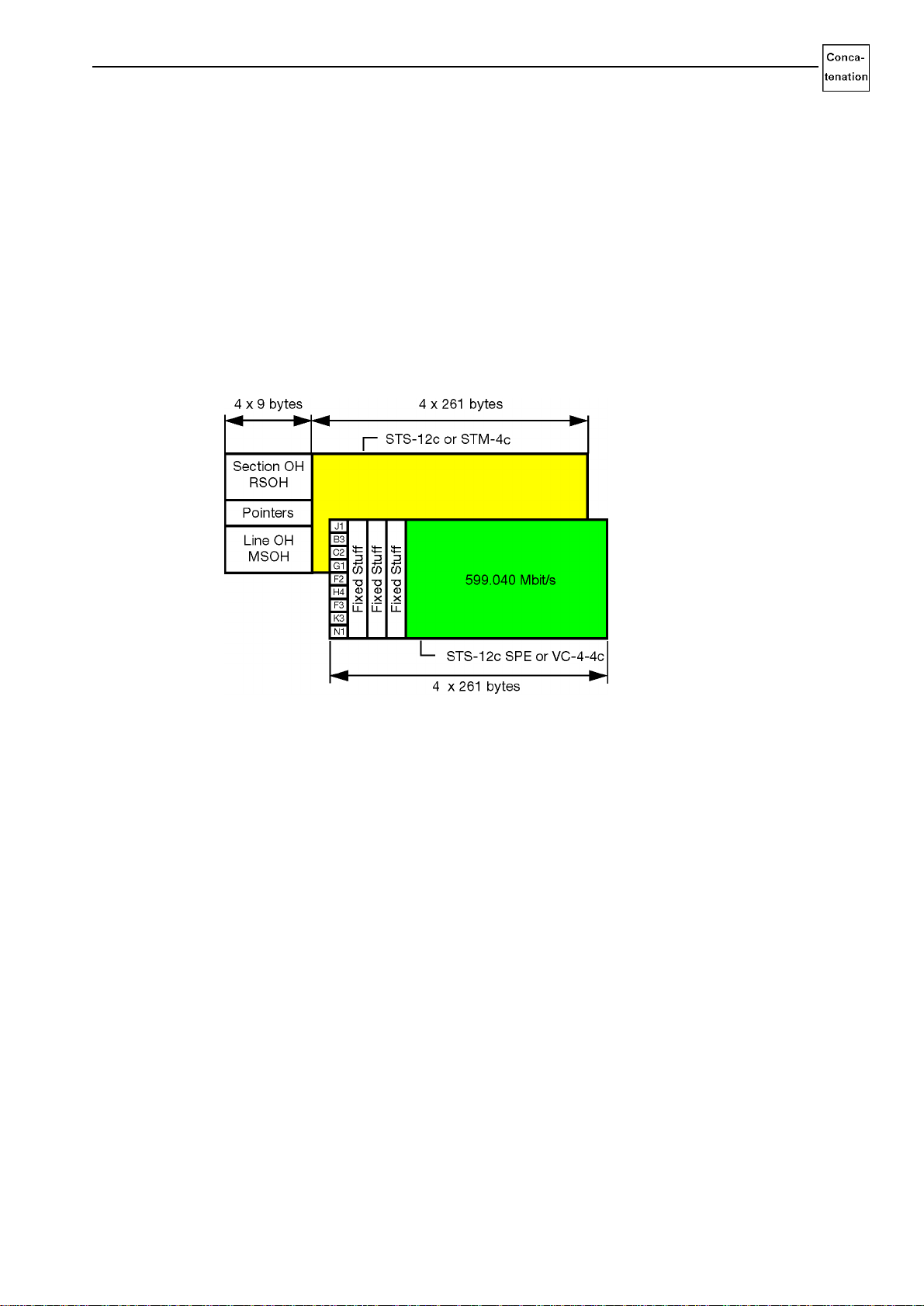
2.1 OC-12c/STM-4c
The “OC-12c/STM-4c” options expand the applications of the virtual instruments (VI) of the
ANT-20 to include the following signal structures:
These signals have a payload bit rate of 599.040 Mbit/s.
Fig. I-1 Contiguous concatenation, OC-12c/STM-4c
The “Signal Structure” VI can be used to set the appropriate mapping for concatenated
containers for the transmitter (Tx) and receiver (Rx).
The following VIs can be used for tests after the settings are made:
•Performance Analyzer
•Anomaly/Defect Analyzer
•Anomaly/Defect Insertion
•Overhead Analyzer
•Overhead Generator
•Pointer Analyzer
•Pointer Generator
•Jitter Generator/Analyzer
•ATM Signal Structure
•ATM Traffic Analyzer
•ATM Background Load Generator
The “OC-12c/STM-4c ERROR TEST (BULK)” and “OC-12c/STM-4c ATM TESTING” options
provide test functions for contiguous concatenation mapping.
With the “OC-12c/STM-4c ERROR TEST (BULK)” option, a bulk signal is mapped into the
concatenated containers. With the “OC-12c/STM-4c ATM TESTING” option, cells are mapped
into the containers.
•STS-12c SPE Contiguous Concatenation
•STS-12v SPE Virtual Concatenation
•VC-4-4c Contiguous Concatenation
•VC-4-4v Virtual Concatenation

Concatenation Options ANT-20/ANT-20E
I-4 Introduction
The “OC-12v/STM-4v VIRTUAL CONCATENATION” option expands all test functions for bulk
signal and cell mapping.
By combining the “OC-12c/STM-4c ATM TESTING” option with the ATM module and the “Jitter
Generator/Analyzer 622 Mbit/s”, it is possible to demonstrate the conformance of ATM network
elements to the jitter requirements of ITU-T, Bellcore and ANSI.
2.1.1 OC-12c/STM-4c TEST ERROR (BULK); (Contiguous Concatenation Mapping)
The “OC-12c/STM-4c ERROR TEST (BULK)” option is used to additionally analyze the bit error
ratio for concatenated containers in accordance with ITU-T O.150. A selectable pseudo-random
bit sequence is mapped into the concatenated container for this measurement.
Fig. I-2 Contiguous concatenation, OC-12c/STM-4c TEST ERROR (BULK)
ANT-20/ANT-20E Concatenation Options
Introduction I-5
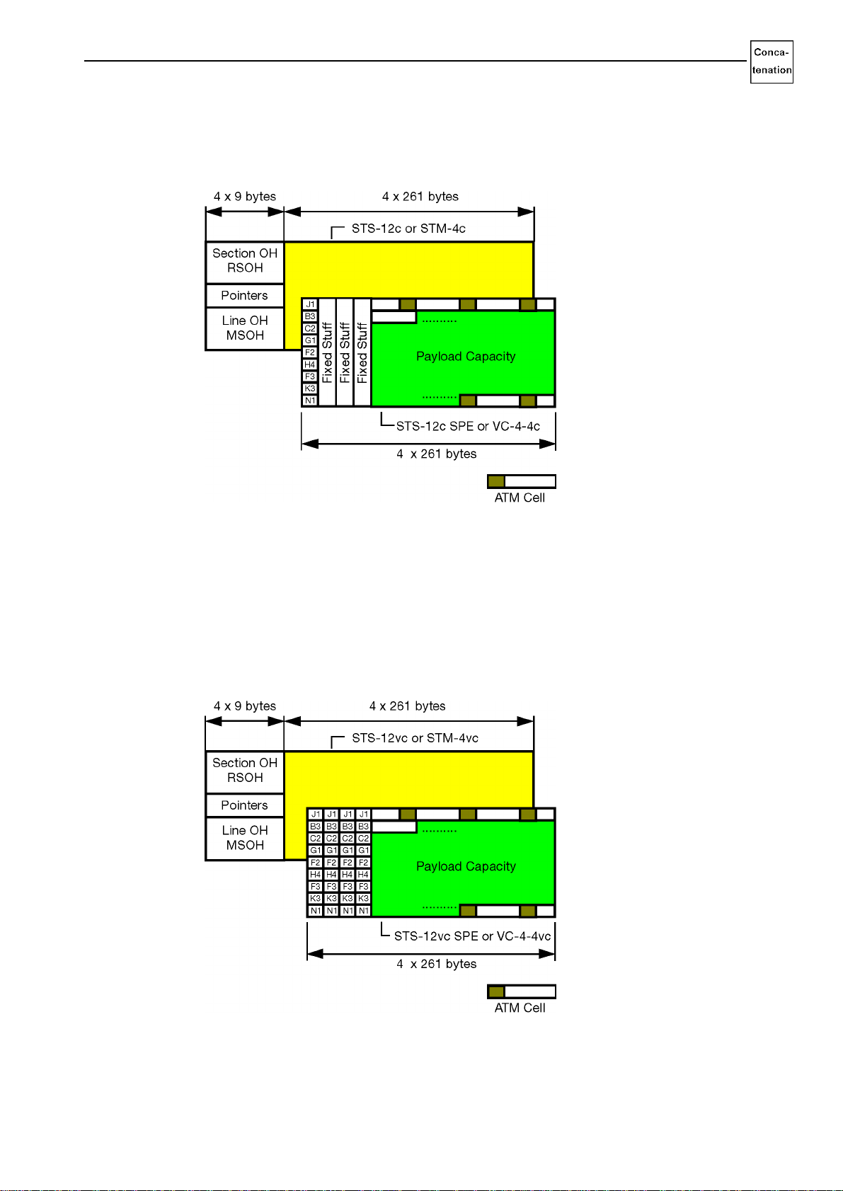
2.1.2 OC-12c/STM-4c ATM TESTING (Contiguous Concatenation Mapping)
The “OC-12c/STM-4c ATM TESTING” option expands the “ATM Module” option (BN 3035/
90.70) for the ANT-20 to allow ATM tests at 622 Mbit/s.
Fig. I-3 Contiguous concatenation, OC-12c/STM-4c ATM TESTING
2.1.3 OC-12v/STM-4v VIRTUAL CONCATENATION (Virtual Concatenation Mapping)
The “OC-12v/STM-4v VIRTUAL CONCATENATION” option provides additional test functions
for this special mapping method.
OC-12vc/STM-4vc virtual concatenation signals have four AU-4-4 pointers instead of one
AU-4-4 pointer.
Fig. I-4 Virtual concatenation, OC-12v/STM-4v VIRTUAL CONCATENATION
Concatenation Options ANT-20/ANT-20E
I-6 Introduction
This allows the VC-4-4v signal to be split into sub-VC-4 signals. The individual sub-VC-4 signals
can be transmitted via different paths, resulting in different propagation delays for the
containers. On termination in the receiver of the ANT-20, the individual VC-4s are recombined
into a single signal.
The main application for the “OC-12v/STM-4v VIRTUAL CONCATENATION” option is in
measuring the propagation delays of individual sub-VC-4s over the different transmission paths.
The delay differences for the individual VC-4 containers can be measured if the Pointer
Analyzer is also used. The delay differences for all four concatenated containers are displayed
versus time, allowing you to assess the suitability of the selected paths for transmission.
Delta pointer actions can be directly set in the ANT-20 Pointer Generator to offset all four
pointers of the concatenated container. In this way, termination in the interface modules of
network elements can be tested. Such modules must be equipped with adequate buffers in
order to equalize out possible differences in delay times.
The Overhead Generator and Overhead Analyzer can be used to manipulate, analyze and
interpret the overhead bytes (SOH, POH or TOH).
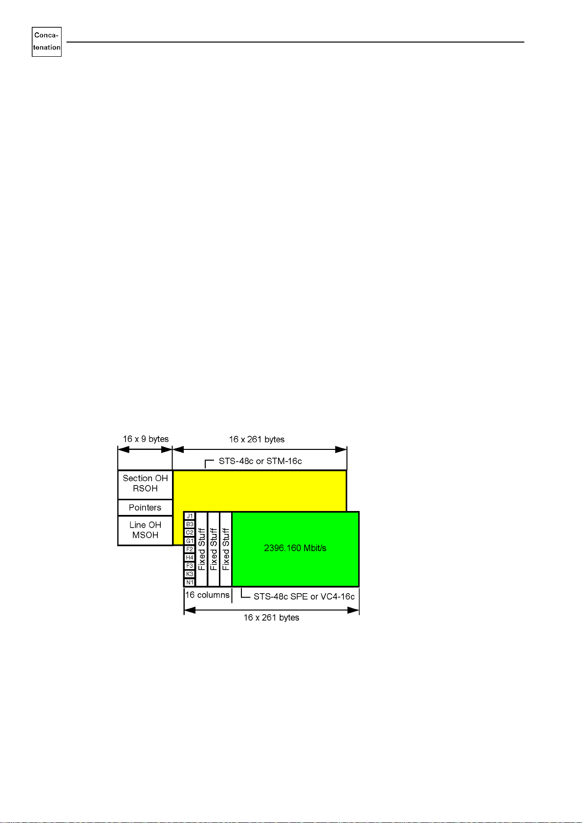
2.2 OC-48c/STM-16c
The “OC-48c/STM-16c” options expand the applications of the virtual instruments (VI) of the
ANT-20 to include the following signal structures:
These signals have a payload bit rate of 2396.160 Mbit/s or 599.040 Mbit/s.
Fig. I-5 Contiguous concatenation, OC-48c/STM-16c
•STS-48c SPE Contiguous Concatenation
•VC-4-16c Contiguous Concatenation
•STS-12c SPE Contiguous Concatenation
•VC-4-4c Contiguous Concatenation
ANT-20/ANT-20E Concatenation Options
Introduction I-7
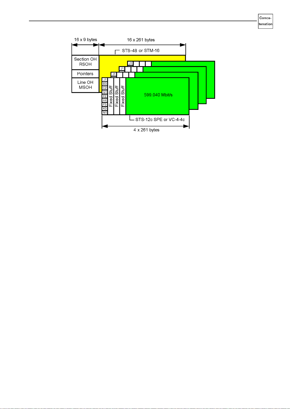
Fig. I-6 Contiguous concatenation, STS-12c SPE or VC-4-4c in OC-48c or STM-16c
The “Signal Structure” VI can be used to set the appropriate mapping for concatenated
containers for the transmitter (Tx) and receiver (Rx).
The following VIs can be used for tests after the settings are made:
•Performance Analyzer
•Anomaly/Defect Analyzer
•Anomaly/Defect Insertion
•Overhead Analyzer
•Overhead Generator
•Pointer Analyzer
•Pointer Generator
•Jitter Generator/Analyzer
•ATM Signal Structure
•ATM Traffic Analyzer
•ATM Background Load Generator
The “OC-48c/STM-16c ERROR TEST (BULK)”, “OC-12c/STM-4c ERROR TEST (BULK)” and
“OC-12c/STM-4c ATM TESTING” options provide test functions for contiguous concatenation
mapping.
With the “OC-48c/STM-16c ERROR TEST (BULK)” and “OC-12c/STM-4c ERROR TEST
(BULK)”options, a bulk signal is mapped into the concatenated containers. With the “OC-12c/
STM-4c ATM TESTING” option, cells are mapped into the containers.
By combining the “OC-12c/STM-4c ATM TESTING” option with the ATM module and the “Jitter
Generator/Analyzer 622 Mbit/s”, it is possible to demonstrate the conformance of ATM network
elements to the jitter requirements of ITU-T, Bellcore and ANSI.
Concatenation Options ANT-20/ANT-20E
I-8 Introduction
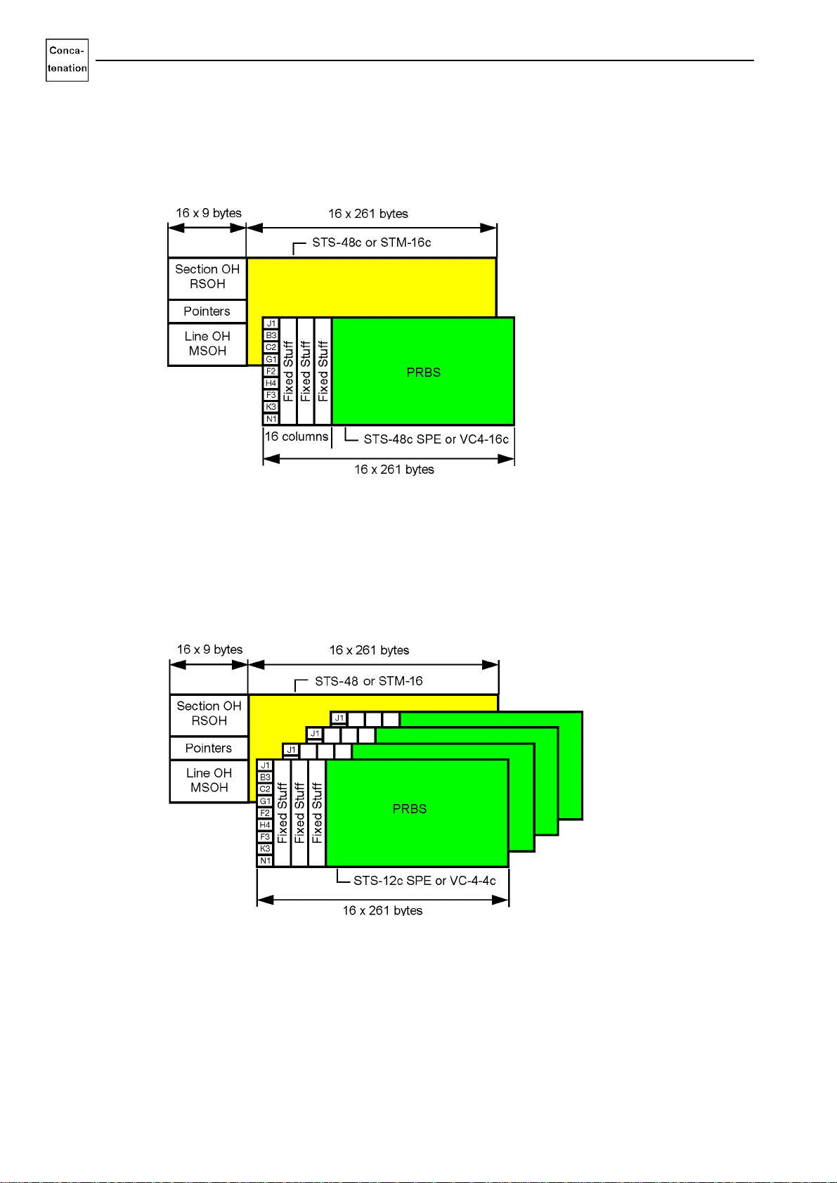
2.2.1 OC-48c/STM-16c ERROR TEST (BULK); (Contiguous Concatenation Mapping)
The “OC-48c/STM-16c ERROR TEST (BULK)” option is used to additionally analyze the bit
error ratio for concatenated containers in accordance with ITU-T O.150. A selectable pseudo-
random bit sequence is mapped into the concatenated container for this measurement.
Fig. I-7 Contiguous concatenation, OC-48c/STM-16c ERROR TEST (BULK)
2.2.2 OC-12c/STM-4c ERROR TEST (BULK); (Contiguous Concatenation Mapping)
The “OC-12c/STM-4c ERROR TEST (BULK)” option is used to additionally analyze the bit error
ratio for concatenated containers in accordance with ITU-T O.150. A selectable pseudo-random
bit sequence is mapped into the concatenated container for this measurement.
Fig. I-8 Contiguous concatenation, STS-12c SPE or VC-4-4c in OC-48c or STM-16c
ANT-20/ANT-20E Concatenation Options
Introduction I-9
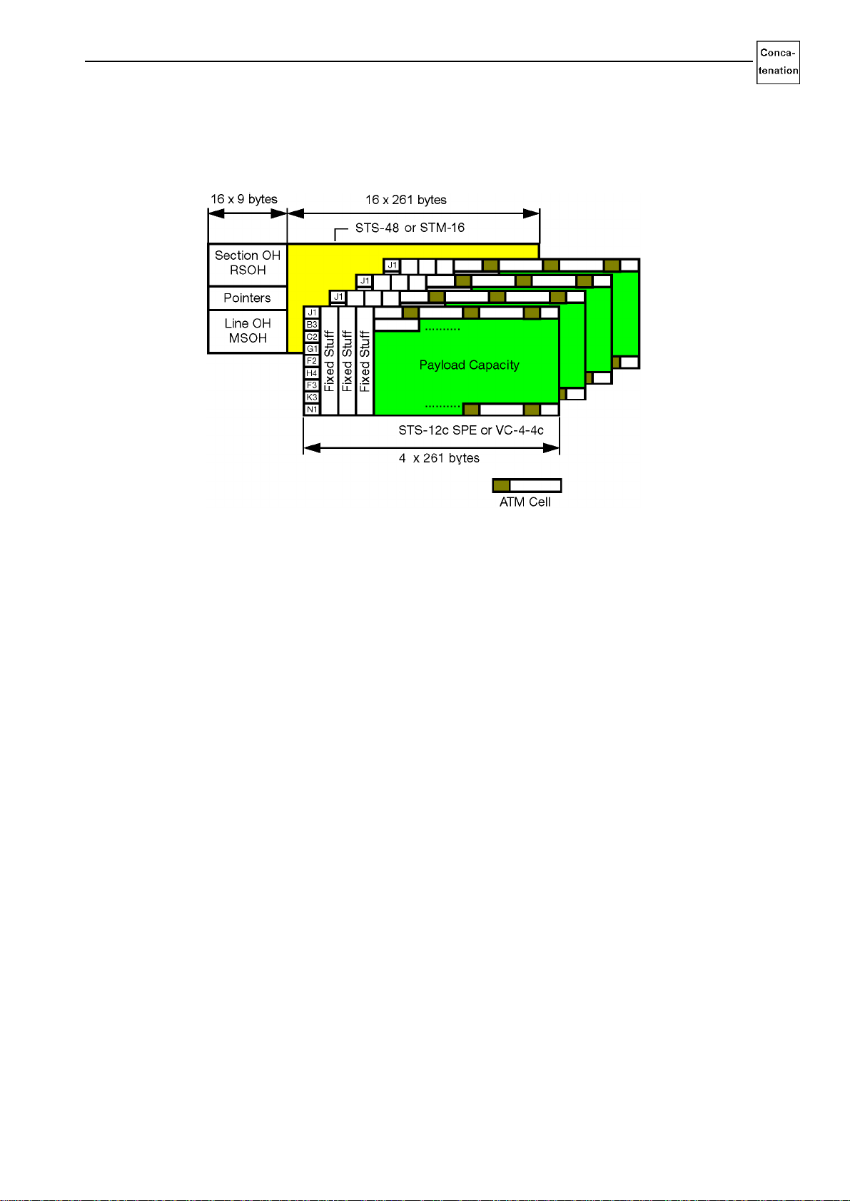
2.2.3 OC-12c/STM-4c ATM TESTING (Contiguous Concatenation Mapping)
The “OC-12c/STM-4c ATM TESTING” option expands the “ATM Module” option (BN 3035/
90.70) for the ANT-20 to allow ATM tests at 622 Mbit/s.
Fig. I-9 Contiguous concatenation and ATM tests, STS-12c/VC-4c in OC-48c or STM-16c

Concatenation Options ANT-20/ANT-20E
I-10 Introduction
3 Operation
The “OC-12c/STM-4c” and “OC-48c/STM-16c” options do not alter the basic operating
procedures for the virtual instruments. Signal structures for these options are set in the “Signal
Structure” VI by means of the “CONCAT.” button.
Other additions are found in the Operating Manual for the Mainframe Instrument under the
descriptions of the various virtual instruments in file section 4:
•Pointer Analyzer
•Pointer Generator
•Overhead Analyzer
•Overhead Generator
•Signal Structure
For ATM applications, additions are found in file section 8 of the ANT-20 Options File.

ANT-20/ANT-20E Concatenation Options
Specifications OC-12c/STM-4c S-1
Specifications OC-12c/STM-4c
These specifications apply to the following options:
OC-12c/STM-4c mapping
The numbers in square brackets […] against the measurement connections correspond to the
numbers printed on the instrument.
Calibrated specifications are marked ***.
1 Generator section
1.1 Digital signal output
1.1.1 Signal output [18], optical
The generator meets the requirements of ITU-T G.957 classes L1.1, L1.2, L1.3, L4.1, L4.2,
L4.3.
Classes S1.1, S1.2 as well as S4.1 and S4.2 can be achieved by inserting an optical attenuator
or the Optical Power Splitter BN 3035/90.49.
LASER ON status display
LED is on when the laser source is active.
OC-12c/STM-4c ERROR TEST (BULK). . . . . . . . . . . . . . . . . . . . . . . . . . . . . . . .BN 3035/90.90
OC-12c/STM-4c ATM TESTING. . . . . . . . . . . . . . . . . . . . . . . . . . . . . . . . . . . . . .BN 3035/90.91
OC-12v/STM-4v VIRTUAL CONCATENATION . . . . . . . . . . . . . . . . . . . . . . . . . .BN 3035/90.92
Connector. . . . . . . . . . . . . . . . . . . . . . . . . . . . . . . . . . . . . . . . . . . . . . . . . . . . . . . . 2.5 mm (PC)
“Fiber to fiber” test adapter for connecting various
2.5 mm plug connectors. . . . . . . . . . . . . . . . . . . . . . . . . . . . . . . . . . . . . . see list of accessories
Output level ***. . . . . . . . . . . . . . . . . . . . . . . . . . . . . . . . . . . . . . . . . . . . . . . . 0 dBm +2/-3 dBm
Reduction in output level
for dual wavelength version . . . . . . . . . . . . . . . . . . . . . . . . . . . . . . . . . . . . . . . . . . . . < 0.5 dBm
Output signal pulse shape . . . . . . . . . . . . . . . . . . . . . . . . . . . . . . . . . . . . . . . . . .to ITU-T G.957
Wavelength (switchable, depending on option) . . . . . . . . . . . . . . .1310 nm (1280 to 1330 nm),
1550 nm (1480 to 1580 nm)
Laser safety class as per EN 60825-1:1994 . . . . . . . . . . . . . . . . . . . . . . . . . . . . . . . . . . . . . . .1

Concatenation Options ANT-20/ANT-20E
S-2 Specifications OC-12c/STM-4c
1.2 Clock generation and bit rates
1.2.1 Clock generation
See “Specifications” for the mainframe instrument.
1.2.2 Bit rate
1.3 SDH and SONET Tx signals
•OC-12c signal generated as per Bellcore GR-253 Standard.
•STM-4c signal generated as per ITU-T Recommendation G.707.
1.3.1 OC-12c/STM-4c Tx signal
OC-12c/STM-4c signal formation:
•Signal generated internally, payload contains bulk signal or ATM cells.
•Complete signal taken from receiver.
1.3.2 Scrambling
Scrambling is as per ITU-T Recommendation G.707.
Scrambling can be activated or deactivated.
OC-12c/STM-4c. . . . . . . . . . . . . . . . . . . . . . . . . . . . . . . . . . . . . . . . . . . . . . . . . . . 622.08 Mbit/s
Other manuals for ANT-20
8
This manual suits for next models
1
Table of contents
Other Wavetek Test Equipment manuals

Wavetek
Wavetek ANT-20 User manual

Wavetek
Wavetek ANT-20 User manual

Wavetek
Wavetek SF10 User manual

Wavetek
Wavetek ANT-20 User manual

Wavetek
Wavetek ANT-20 User manual

Wavetek
Wavetek ANT-20 User manual

Wavetek
Wavetek ANT-20 User manual

Wavetek
Wavetek ANT-20 User manual

Wavetek
Wavetek 147 User manual

Wavetek
Wavetek ANT-20 User manual


