Wavetek ANT-20 User manual

BN 3035/98.35
ANT-20, ANT-20E
Advanced Network Tester
for BN 3035/90.70
and BN 3035/90.80
ATM Mappings
BN 3035/90.71 to 90.77
Software Version 7.20
Operating Manual
8

Please direct all enquiries to your
local W avetek Wandel Goltermann sales
company. The addresse s are given at the
end of this handbook.
Copyrig hts
This produc t orparts of it are based upon
Recommendations and/or Standards o f the
Standardization Sector o f the International
Telecommunication Un ion- ITU-T and/or o f the
European Te lecommunicat ions Standards Institut e -
ETSI. These Recom mendations an d Standards are
subject to copyrights of thes e organizations. Witho ut
written permission of the ITU -T and/or ETSI it isnot
permitted to copy ITU-T Reco mmendations o r ETSI
standa rds or parts thereof and/or make them avai lable
to third parties.
Wavetek Wandel Golterm ann
Ening en GmbH & Co.
Mühleweg 5, 72800 Eningen u. A.
© 2000
Author: MDD/TD
Translator: JohnNutley
Order no.: BN 3035/98.35
Edition: 06/00.07(V 7.20)
Previous edition:
05/00.04(V 7.1)
Subject to change without notice
Our normal guarantee and delivery
terms apply
Printed in Germany

i
ANT-20/ANT-20E ATM Mappings
Contents
Specifications
1 STM-1 C4, ATM in 155.52 Mbit/s mapping . . . . . . . . . . . . . . . . . . . .S-1
2 STS-3c, ATM in 155.52 Mbit/s mapping . . . . . . . . . . . . . . . . . . . . . .S-2
3 STS-1, ATM in 51.840 Mbit/s mapping . . . . . . . . . . . . . . . . . . . . . . . S-3
4 E4, ATM in 139.264 Mbit/s mapping . . . . . . . . . . . . . . . . . . . . . . . . .S-4
4.1 Overhead. . . . . . . . . . . . . . . . . . . . . . . . . . . . . . . . . . . . . . . .S-4
4.2 Alarm generation (defects) . . . . . . . . . . . . . . . . . . . . . . . . . .S-4
4.3 Error insertion (anomalies) . . . . . . . . . . . . . . . . . . . . . . . . . .S-5
4.4 Error measurement (anomalies) . . . . . . . . . . . . . . . . . . . . . .S-5
4.5 Alarm detection (defects) . . . . . . . . . . . . . . . . . . . . . . . . . . .S-5
5 E3, ATM in 34.368 Mbit/s mapping . . . . . . . . . . . . . . . . . . . . . . . . . . S-6
5.1 Overhead. . . . . . . . . . . . . . . . . . . . . . . . . . . . . . . . . . . . . . . .S-6
5.2 Alarm generation (defects) . . . . . . . . . . . . . . . . . . . . . . . . . .S-6
5.3 Error insertion (anomalies) . . . . . . . . . . . . . . . . . . . . . . . . . .S-7
5.4 Error measurement (anomalies) . . . . . . . . . . . . . . . . . . . . . .S-7
5.5 Alarm detection (defects) . . . . . . . . . . . . . . . . . . . . . . . . . . .S-7
6 E1, ATM in 2.048 Mbit/s mapping . . . . . . . . . . . . . . . . . . . . . . . . . . .S-8
7 DS3, ATM in 44.736 Mbit/s mapping (PLCP, HEC based) . . . . . . . . S-9
7.1 PLCP-based Mapping. . . . . . . . . . . . . . . . . . . . . . . . . . . . . .S-9
7.1.1 Overhead. . . . . . . . . . . . . . . . . . . . . . . . . . . . . . . . . . . . . . . .S-9
7.1.2 Alarm generation (defects) . . . . . . . . . . . . . . . . . . . . . . . . .S-10
7.1.3 Error insertion (anomalies) . . . . . . . . . . . . . . . . . . . . . . . . .S-10
7.1.4 Error measurement (anomalies) . . . . . . . . . . . . . . . . . . . . .S-11
7.1.5 Alarm detection (defects) . . . . . . . . . . . . . . . . . . . . . . . . . .S-11
7.2 HEC-based Mapping. . . . . . . . . . . . . . . . . . . . . . . . . . . . . . S-12
7.2.1 Alarm generation (defects) . . . . . . . . . . . . . . . . . . . . . . . . .S-12
7.2.2 Error insertion (anomalies) . . . . . . . . . . . . . . . . . . . . . . . . .S-12
7.2.3 Error measurement (anomalies) . . . . . . . . . . . . . . . . . . . . .S-12
7.2.4 Alarm detection (defects) . . . . . . . . . . . . . . . . . . . . . . . . . .S-13

ii
ATM Mappings ANT-20/ANT-20E
8 DS1, ATM in 1.544 Mbit/s mapping. . . . . . . . . . . . . . . . . . . . . . . . . S-14
8.1 Alarm generation (defects) . . . . . . . . . . . . . . . . . . . . . . . . . S-14
8.2 Error insertion (anomalies) . . . . . . . . . . . . . . . . . . . . . . . . . S-14
8.3 Error measurement (anomalies). . . . . . . . . . . . . . . . . . . . . S-14
8.4 Alarm detection (defects) . . . . . . . . . . . . . . . . . . . . . . . . . . S-15
9 STM-1 C3, ATM in 155.52 Mbit/s mapping . . . . . . . . . . . . . . . . . . . S-16
10 STS-1 SPE, ATM in 44.736 Mbit/s mapping . . . . . . . . . . . . . . . . . . S-17
11 VC3, ATM in 44.736 Mbit/s mapping. . . . . . . . . . . . . . . . . . . . . . . . S-17
ANT-20/ANT-20E ATM Mappings
Specifications S-1
Specifications
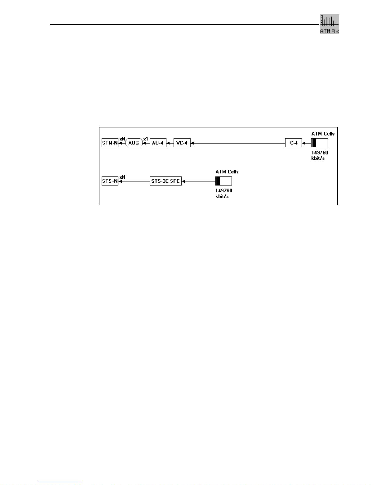
1 STM-1 C4, ATM in 155.52 Mbit/s mapping
This mapping structure is included in the following instrument versions and options:
•ATM Module, BN 3035/90.70
•Broadband Analyzer/Generator, BN 3035/90.80
Fig. S-1 150 Mbit/s in STM-1/STS-3c ATM cell stream mapping structure
For the following topics please refer to the specifications of the “STM-1 Mappings” file:
•Overhead
•Alarm generation (defects)
•Error insertion (anomalies)
•Overhead evaluation
•Error measurement (anomalies)
•Alarm detection (defects)

ATM Mappings ANT-20/ANT-20E
S-2 Specifications
2 STS-3c, ATM in 155.52 Mbit/s mapping
This mapping structure is included in the following instrument versions and options:
•ATM Module, BN 3035/90.70
•Broadband Analyzer/Generator, BN 3035/90.80
For the following topics please refer to the specifications of the “STS-1 Mapping” file (section
“STS-3c Mapping”:
•Overhead
•Alarm generation (defects)
•Error insertion (anomalies)
•Overhead evaluation
•Error measurement (anomalies)
•Alarm detection (defects)
ANT-20/ANT-20E ATM Mappings
Specifications S-3
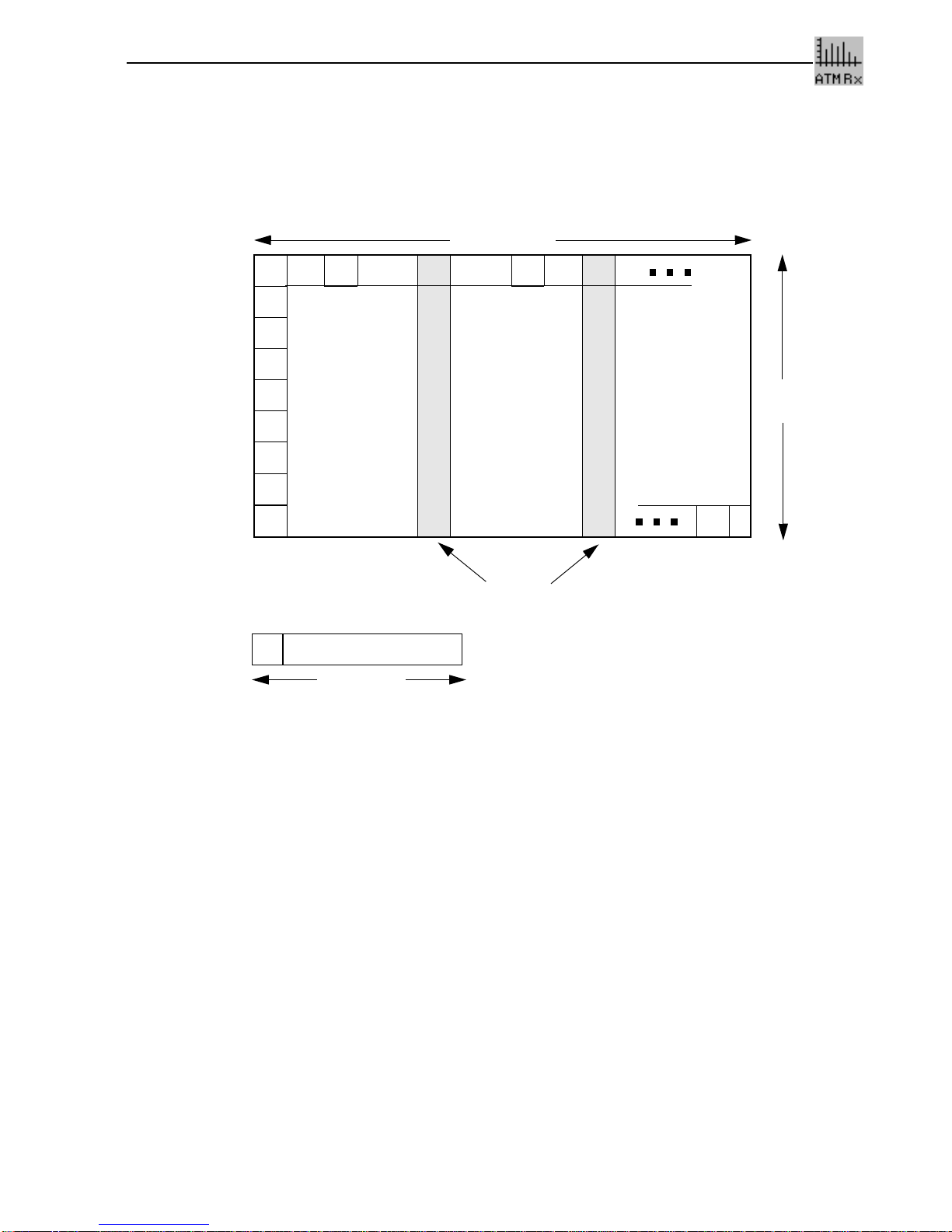
3 STS-1, ATM in 51.840 Mbit/s mapping
Option 3035/90.71
•Includes the ATM mapping for STS-1 in accordance with ITU-T G.707 and ANSI Draft
T1.105.02-199X.
Fig. S-2 ATM mapping for STS-1 (51.840 Mbit/s)
For the following topics please refer to the specifications of the “STS-1 Mapping” file:
•Overhead
•Alarm generation (defects)
•Error insertion (anomalies)
•Overhead evaluation
•Error measurement (anomalies)
•Alarm detection (defects)
87 octets
J1
B3
C2
G1
F2
H4
Z3
Z4
Z5
HH
H
H
53 octets
STS-1 POH fixed
ATM cell
stuffing
9 rows

ATM Mappings ANT-20/ANT-20E
S-4 Specifications
4 E4, ATM in 139.264 Mbit/s mapping
Option 3035/90.72
•Frames to G.832.
•ATM mapping to G.804.
4.1 Overhead
Table S-1 Overhead contents
4.2 Alarm generation (defects)
The following alarm types (defects) can be generated:
Table S-2 Available alarm types (defects)
Overhead byte Option 3035/90.72
FA1(hex) “F6”
FA2 (hex) “28”
EM (hex) Inserted via parity formation
TR (ASCII) “WG E4-TRACE”
MA (hex) “10”
NR (hex) “00”
GC (hex) “00”
P1 (hex) “00”
P2 (hex) “00”
Defect Sensor function test Sensor thresholds
On/Off M in N
AIS Yes -
LOF Yes M = 1 to N-1;
N = 1 to 8001
RDI Yes M = 1 to N-1;
N = 1 to 8001
UNEQ Yes M = 1 to N-1;
N = 1 to 8001
PLM Yes M = 1 to N-1;
N = 1 to 8001
TIM ja -

ANT-20/ANT-20E ATM Mappings
Specifications S-5
4.3 Error insertion (anomalies)
Table S-3 Available error types (anomalies) and trigger modes
4.4 Error measurement (anomalies)
The following anomalies can be evaluated and displayed in addition to those described in the
Mainframe “Specifications”.
Table S-4 LED indication of possible anomalies
4.5 Alarm detection (defects)
The following defects can be evaluated and displayed in addition to the alarm types described
in the Mainframe “Specifications”.
Table S-5 LED indication of possible defects
Trigger modes . . . . . . . . . . . . . . . . . . . . . . . . . . . . . . . . . . . . . . . . . . . . . . . . . . . Single or Rate
Error type, anomaly Single Rate
FAS Yes 2E-3 to 1E-8
EM (BIP-8) Yes 2E-3 to 1E-10
REI Yes 5E-5 to 1E-10
Anomaly LED
FAS FAS
EM (BIP-8) B1/B2
REI -
Defect LED
AIS AIS
LOF LOF/OOF
RDI RDI
UNEQ HP-UNEQ
PLM HP-PLM
TIM -

ATM Mappings ANT-20/ANT-20E
S-6 Specifications
5 E3, ATM in 34.368 Mbit/s mapping
Option 3035/90.74
•Frames to G.832.
•ATM mapping to G.804
5.1 Overhead
Table S-6 Overhead contents
5.2 Alarm generation (defects)
The following alarm types (defects) can be generated:
Table S-7 Available alarm types (defects)
Overhead byte Option 3035/90.74
FA1(hex) “F6”
FA2 (hex) “28”
EM (hex) Inserted via parity formation
TR (ASCII) “WG E3-TRACE
MA (hex) “10”
NR (hex) “00”
GC (hex) “00”
Defect Sensor function test Sensor thresholds
On / Off M in N
AIS Yes -
LOF Yes M = 1 to N-1;
N = 1 to 8001
RDI Yes M = 1 to N-1;
N = 1 to 8001
UNEQ Yes M = 1 to N-1;
N = 1 to 8001
PLM Yes M = 1 to N-1;
N = 1 to 8001
TIM Yes -

ANT-20/ANT-20E ATM Mappings
Specifications S-7
5.3 Error insertion (anomalies)
Table S-8 Available error types (anomalies) and trigger modes
5.4 Error measurement (anomalies)
The following anomalies can be evaluated and displayed in addition to the error types available
in the Mainframe.
Table S-9 LED indication of possible anomalies
5.5 Alarm detection (defects)
The following defects can be evaluated and displayed in addition to the alarm types available in
the Mainframe.
Table S-10 LED indication of possible defects
Trigger modes . . . . . . . . . . . . . . . . . . . . . . . . . . . . . . . . . . . . . . . . . . . . . . . . . . . Single or Rate
Error type, anomaly Single Rate
FAS Yes 2E-3 to 1E-8
EM (BIP-8) Yes 2E-3 to 1E-10
REI Yes 2E-4 to 1E-10
Anomaly LED
FAS FAS
EM (BIP-8) B1/B2
REI -
Defect LED
AIS AIS
LOF LOF/OOF
RDI RDI
UNEQ HP-UNEQ
PLM HP-PLM
TIM -
ATM Mappings ANT-20/ANT-20E
S-8 Specifications
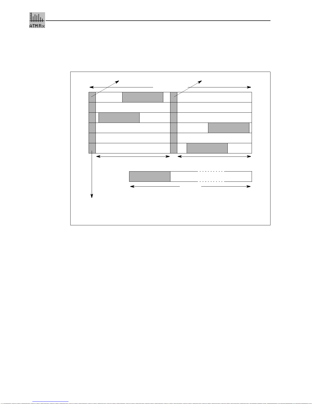
6 E1, ATM in 2.048 Mbit/s mapping
Option 3035/90.75
•ATM mapping according to ITU-T G.804.
Fig. S-3 ATM mapping for E1 (2048 kbit/s)
For the following topics please refer to the specifications of the “STM-1-Mapping” file:
•Alarm generation (defects)
•Error insertion (anomalies)
•Error measurement (anomalies)
•Alarm detection (defects)
Header
Header
Header
Header
Header
53 octets
256 bits/125 µs
TS0 TS16: signalling
Mapping section for ATM cells: 30 octets (TS1 to TS15 and TS17 to TS31)
Supports F3 OAM functions:
– Detection of loss of frame alignment
– Performance monitoring (CRC-4)
– Transmission of FERF and LCD
– Performance reporting

ANT-20/ANT-20E ATM Mappings
Specifications S-9
7 DS3, ATM in 44.736 Mbit/s mapping (PLCP, HEC based)
Option 3035/90.73
7.1 PLCP-based Mapping
The ATM cells are firs mapped into PLCP frames (Physical Layer Convergence Protocol) as per
G.804. The PLCP frame slips bit-synchronously (Nibble-aligned floating-4 bit) into DS3 C Parity
frames as per G.804 (G.704). For more information refer to the specifications of the “STM-1-
Mapping” file (section “DS3 Mapping”):
7.1.1 Overhead
DS3: PLCP based ATM mapping
All values are hexadecimal.
B1 is formed from the POH and ATM cells of the 12 rows of the previous frame.
O H
1 2 3
(POI) 4
(POH) 5 6
1A1
F6 A2
28 P11
2C Z6
00 ATM Cell
2A1
F6 A2
28 P10
29 Z5
00 ATM Cell
3A1
F6 A2
28 P09
25 Z4
00 ATM Cell
4A1
F6 A2
28 P08
20 Z3
00 ATM Cell
5A1
F6 A2
28 P0
1C Z2
00 ATM Cell
6A1
F6 A2
28 P06
19 Z1
00 ATM Cell
7A1
F6 A2
28 P05
15 X
00 ATM Cell
8A1
F6 A2
28 P04
10 B1 ATM Cell
9A1
F6 A2
28 P03
0D G1
00 ATM Cell
10 A1
F6 A2
28 P02
08 X
00 ATM Cell
11 A1
F6 A2
28 P01
04 X
00 ATM Cell
12 A1
F6 A2
28 P00
01 C1 ATM Cell Trailer
C

ATM Mappings ANT-20/ANT-20E
S-10 Specifications
7.1.2 Alarm generation (defects)
The following alarm types (defects) can be generated:
Table S-11 Available alarm types (defects)
7.1.3 Error insertion (anomalies)
Table S-12 Available error types (anomalies) and trigger types
Defect Sensor function test Sensor thresholds
on/off M in N
AIS_DS3 yes -
IDLE_DS3 yes -
LOF_DS3 yes -
YELLOW_DS3 (RDI) yes -
PLCP_LOF yes M = 1 to N-1;
N = 1 to 8000
PLCP_RAI yes
Trigger types . . . . . . . . . . . . . . . . . . . . . . . . . . . . . . . . . . . . . . . . . . . . . . Single error, error rate
Error type, anomaly Single Rate
FE_DS3 yes -
Parity_DS3 yes -
FEBE_DS3 yes -
PLCP_FAS yes 1E-3 to 1E-7
PLCP_B1 yes 1E-3 to 1E-8
PLCP_REI(FEBE) yes 1E-3 to 1E-8

ANT-20/ANT-20E ATM Mappings
Specifications S-11
7.1.4 Error measurement (anomalies)
The following error types can be displayed and evaluated in addition to the error types provided
by the Mainframe.
Table S-13 LED display of possible anomalies
7.1.5 Alarm detection (defects)
The following alarms can be displayed and evaluated in addition to the defects provided by the
Mainframe.
Table S-14 LED display of possible defects
Anomaly LED
FE_DS3, MFE_DS3 FAS/CRC
P_DS3, CP_DS3 -
FEBE_DS3 -
PLCP_FAS FAS/CRC
PLCP_B1 B1/B2
PLCP_REI (FEBE) -
Defect LED
AIS_DS3 AIS
LOF_DS3, OOF_DS3 LOF/LCD
YELLOW_DS3 RDI
IDLE_DS3 -
PLCP_LOF LOF/LCD
PLCP_RAI -

ATM Mappings ANT-20/ANT-20E
S-12 Specifications
7.2 HEC-based Mapping
The G.704 multiframe is used for HEC-based mapping of ATM cells into 44.736 Mbit/s as per
G.804.
7.2.1 Alarm generation (defects)
Table S-15 Alarm generation (defects): Available alarm types
7.2.2 Error insertion (anomalies)
Table S-16 Error insertion (anomalies): Available error types and trigger types
7.2.3 Error measurement (anomalies)
Table S-17 Error measurement (anomalies): LED display of possible anomalies
Defect Sensor
function test
on/off
AIS_DS3 yes
IDLE_DS3 yes
LOF_DS3 yes
YELLOW_DS3 (RDI) yes
Error type, anomaly Single
FE_DS3 yes
Parity_DS3 yes
FEBE_DS3 yes
Anomaly LED
FE_DS3, MFE_DS3 FAS/CRC
P_DS3, CP_DS3 -
FEBE_DS3 -

ANT-20/ANT-20E ATM Mappings
Specifications S-13
7.2.4 Alarm detection (defects)
Table S-18 Alarm detection (defects): LED display of possible defects
Defect LED
AIS AIS
LOF_DS3, OOF_DS3 LOF/LCD
YELLOW_DS3 RDI
IDLE_DS3 -

ATM Mappings ANT-20/ANT-20E
S-14 Specifications
8 DS1, ATM in 1.544 Mbit/s mapping
Option 3035/90.76
8.1 Alarm generation (defects)
Table S-19 Alarm generation (defects): Available defects
8.2 Error insertion (anomalies)
Table S-20 Error insertion (anomalies): Available anomalies and trigger mode
8.3 Error measurement (anomalies)
The following error types can be displayed and evaluated in addition to the error types provided
by the Mainframe.
Table S-21 Error measurement (anomalies): LED display of available anomalies
Defect Sensor function test
on/off
AIS_DS1 yes
LOF_DS1 yes
YELLOW_DS1 yes
Trigger types . . . . . . . . . . . . . . . . . . . . . . . . . . . . . . . . . . . . . . . . . . . . . . . . . . . . . . .Single error
Anomaly Single
FE_DS1 yes
CRC6 yes
Anomaly LED
FE_DS1 FAS/CRC
CRC6 FAS/CRC

ANT-20/ANT-20E ATM Mappings
Specifications S-15
8.4 Alarm detection (defects)
The following alarms can be displayed and evaluated in addition to the defects provided by the
Mainframe.
Table S-22 Alarm detection (defects): LED display of available defects
Defect LED
AIS_DS1 AIS
LOF_DS1, OOF_DS1 LOF/LCD
YELLOW_DS1 RDI
ATM Mappings ANT-20/ANT-20E
S-16 Specifications
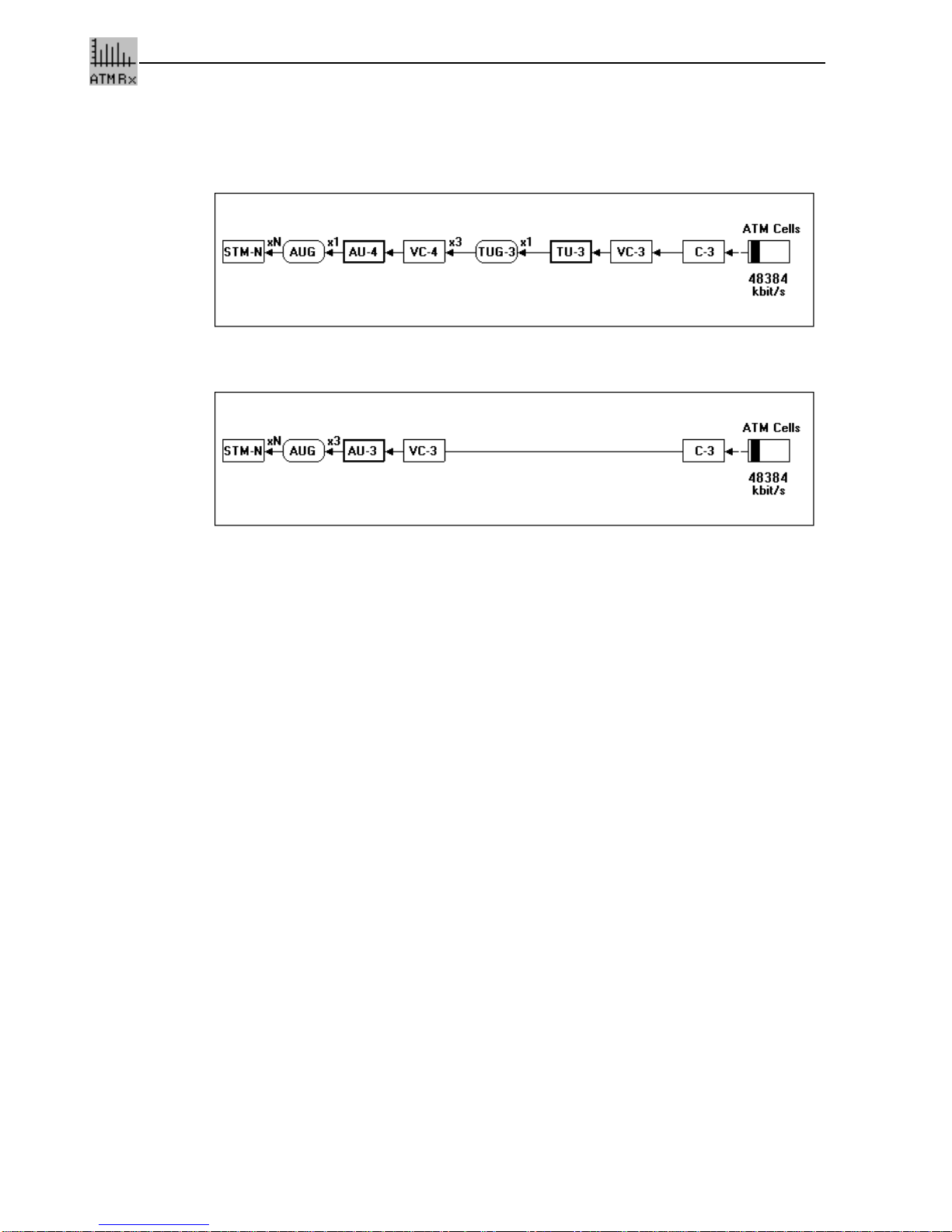
9 STM-1 C3, ATM in 155.52 Mbit/s mapping
Option 3035/90.77
Fig. S-4 Mapping structure AU-4: ATM “→” C-3 “→” AU-4“→” STM-1
Fig. S-5 Mapping structure AU-3: ATM “→” C-3 “→” AU-3“→” STM-1
For the following topics please refer to the specifications of the “STM-1Mapping” file:
•Overhead
•Alarm generation (defects)
•Error insertion (anomalies)
•Overhead evaluation
•Error measurement (anomalies)
•Alarm detection (defects)
Other manuals for ANT-20
8
This manual suits for next models
1
Table of contents
Other Wavetek Test Equipment manuals

Wavetek
Wavetek ANT-20 User manual

Wavetek
Wavetek 147 User manual

Wavetek
Wavetek ANT-20 User manual

Wavetek
Wavetek ANT-20 User manual

Wavetek
Wavetek ANT-20 User manual

Wavetek
Wavetek ANT-20 User manual

Wavetek
Wavetek SF10 User manual

Wavetek
Wavetek ANT-20 User manual

Wavetek
Wavetek ANT-20 User manual

Wavetek
Wavetek ANT-20 User manual


