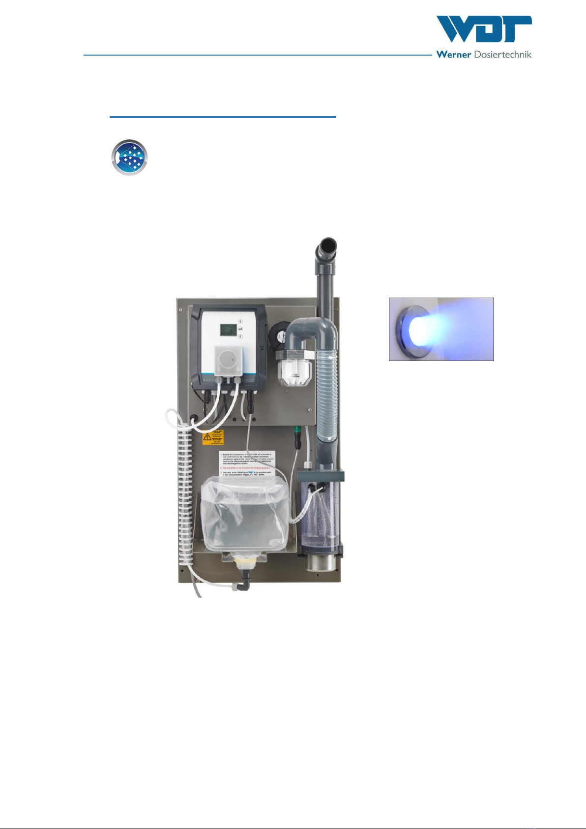
Brine Fogging System Type SOLFOG V3
Index: 02 Change date: 19/09/2023 OI No.: BA DW 042-02 Solfog V3 CB36 EN.docx Page 3 of 65
Table of contents
1About these instructions / general....................................................................................... 5
1.1 Scope of applicability ........................................................................................................5
1.2 Target group......................................................................................................................5
1.3 Symbols used ....................................................................................................................5
1.4 Further means of representation......................................................................................7
1.5 Warranty ...........................................................................................................................7
1.5.1 General terms and conditions of warranty.......................................................................7
1.6 Additional information......................................................................................................8
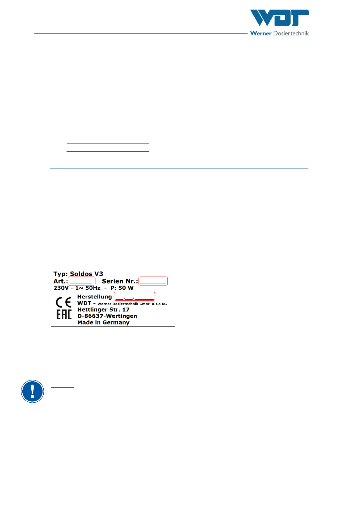
1.7 Information regarding support queries/ identification plate ...........................................8
2Safety notices ..................................................................................................................... 9
2.1 Intended use .....................................................................................................................9
2.2 Personnel ..........................................................................................................................9
2.3 Electrical system..............................................................................................................10
2.4 Operation of the device ..................................................................................................10
3Scope of delivery / accessories / functional description...................................................... 12
3.1 Scope of delivery / accessories .......................................................................................12
3.2 Structure of the overall system.......................................................................................12
3.3 Functional description.....................................................................................................13
3.4 Description of components.............................................................................................13
3.4.1 Control unit .....................................................................................................................13
3.4.2 Brine dosing ....................................................................................................................13
3.4.3 Ultrasonic fog maker.......................................................................................................14
3.4.4 Dosing unit for the scenting............................................................................................14
3.4.5 Button plate (option) ......................................................................................................14
3.4.6 Lighting system for fog outlet (option)...........................................................................15
3.5 Technical data .................................................................................................................15
4Transport and storage....................................................................................................... 16
4.1 General safety notices ....................................................................................................16
4.2 Packaging ........................................................................................................................16
4.3 Temporary storage of the device....................................................................................16
4.4 Storage of fragrance oil concentrates / brine.................................................................16
5Mechanical installation ..................................................................................................... 17
5.1 General safety notices ....................................................................................................17
5.2 Select the installation site...............................................................................................17
5.3 Installation notices..........................................................................................................17
5.4 Install SOLFOG V3............................................................................................................18
5.5 Fog maker pipe connection.............................................................................................18
5.5.1 Install the piping..............................................................................................................18
6Electrical installation......................................................................................................... 22
6.1 Safety notices..................................................................................................................22
6.2 Electrical connection.......................................................................................................22
6.3 Additional connection options........................................................................................22
7Commissioning.................................................................................................................. 23
7.1 General safety notices ....................................................................................................23
7.2 General remarks..............................................................................................................23
7.3 Commissioning steps.......................................................................................................23
7.4 Display and controls........................................................................................................24
7.5 Insert the roller carrier at the fragrance pump...............................................................24
7.6 Disassembling the roller carrier......................................................................................26
7.7 Switching on the device ..................................................................................................26
7.7.1 Start query / initial start of the device............................................................................26
7.7.2 Reactivating the device...................................................................................................27
7.8 Carry out disinfection with politainer change.................................................................27
7.8.1 General information regarding disinfection ...................................................................27
7.8.2 Disinfection procedure....................................................................................................28


