Weber Ultrasonics SONIC DIGITAL HS MD User manual

Operating manual - part no.: M21201WUGB
Date of operating manual: 19.01.2015
Version of operating manual: 005
Operating manual EN
Ultrasonic DIN rail generator
SONIC DIGITAL HS
Versions MD/MFD
MULTI PURPOSE

All rights reserved. This documentation is protected by copyright. WEBER Ultrasonics reserves all
rights not expressly granted. This documentation may not be duplicated, distributed or made pub-
licly available in any other way without prior written consent or in legally permitted cases.
We reserve the right to make changes without giving prior notice. The original document was published in
German (the official language of the manufacturer). All translations are copies of the original document.
Copyright 2015 by WEBER Ultrasonics, Karlsbad-Ittersbach (D)
Production, sales and service:
WEBER Ultrasonics GmbH Phone: +49 (0)72 48 / 92 07-0
Im Hinteracker 7 Fax: +49 (0)72 48 / 92 07-11
Germany www.weber-ultrasonics.de

I
Table of contents
1Introduction....................................................................................................................................1
1.1 About WEBER Ultrasonics.........................................................................................................1
Success through customer-oriented ultrasonic solutions .....................................................1
1.2 About the device ........................................................................................................................2
1.3 Purpose of the ultrasonic welding generator..............................................................................2
1.4 Validity of the operating manual.................................................................................................3
1.4.1 Type HS MD/MFD ................................................................................................................3
1.5 About this document ..................................................................................................................5
1.5.1 Purpose ................................................................................................................................5
1.5.2 Target groups .......................................................................................................................5
1.5.3 General structure..................................................................................................................5
1.5.4 Abbreviations used...............................................................................................................6
1.5.5 Signal words used ................................................................................................................6
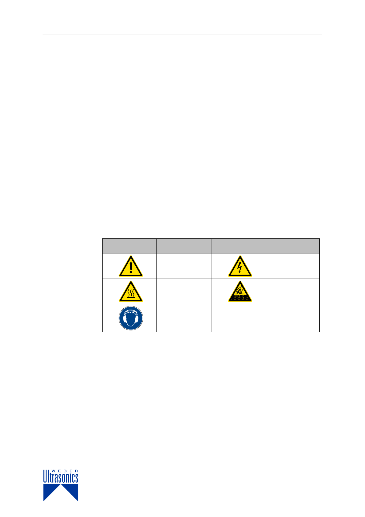
1.5.6 Pictograms and safety instructions.......................................................................................6
2Safety.............................................................................................................................................. 7
2.1 Personnel requirements.............................................................................................................7
2.2Operating conditions..................................................................................................................8
2.3 Safety concept of the manufacturer ...........................................................................................8
2.3.1 Conversions or modifications................................................................................................8
2.4 Responsibilities of the operator..................................................................................................9
2.5 Responsibilities of operating personnel ...................................................................................10
2.6 Environmental protection and emissions .................................................................................11
3Warranty.......................................................................................................................................12
3.1 Exclusion of warranty...............................................................................................................12
4EU Declaration of Conformity ....................................................................................................13
5Generator description.................................................................................................................14
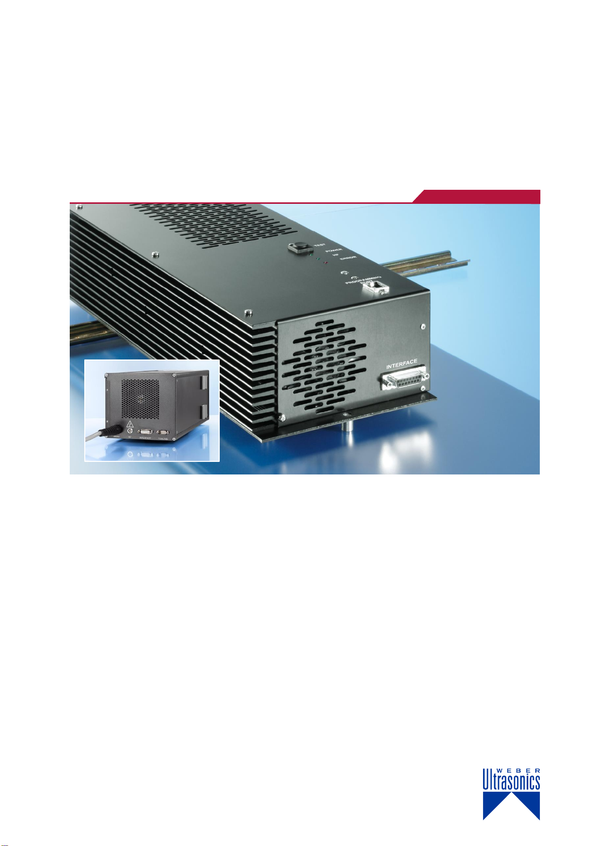
5.1 Housing....................................................................................................................................15
5.1.1 Housing of the HS MD / MFD .............................................................................................15
5.2 Connectors...............................................................................................................................16
5.2.1 Model HS MD / MFD...........................................................................................................16
5.2.2 PIN assignment, mains connection ....................................................................................17
5.2.3 PIN assignment, converter connection...............................................................................17
5.2.4 Assignment of the 15-pole interface socket........................................................................18
5.2.5 PIN assignment, hardware tooling interface.......................................................................21
5.2.6 RS-485 Interface (optional).................................................................................................23
6Installation and connection........................................................................................................24
6.1 Installation................................................................................................................................25
6.2 Installation with angled adapter................................................................................................26
6.3 Mains connection.....................................................................................................................27
6.3.1 Supply ratings.....................................................................................................................27
6.3.2 Cable quality and cable routing ..........................................................................................27
7Operation....................................................................................................................................... 28
7.1 Control and display elements...................................................................................................28
7.1.1 Generator HS MD / MFD....................................................................................................28
7.2 Switching on.............................................................................................................................29
7.3 Switching off.............................................................................................................................30
7.4 Setting up, programming and controlling the ultrasonic generator...........................................30

II
8Specifications..............................................................................................................................31
8.1 Generator HS MD /MFD...........................................................................................................31
8.1.1Rating plate.........................................................................................................................31
9Troubleshooting ..........................................................................................................................32
9.1 Resetting malfunctions.............................................................................................................32
9.2 Eliminating malfunctions ..........................................................................................................32
10 Quality assurance........................................................................................................................ 36
11 General maintenance instructions............................................................................................. 37
11.1 Safety.......................................................................................................................................37
11.2 Care and maintenance.............................................................................................................37
11.3 Maintenance and inspection list...............................................................................................38
11.4 Maintenance.............................................................................................................................39
11.5 Repair work..............................................................................................................................39
12 Life cycle......................................................................................................................................40
12.1 Transport..................................................................................................................................40
12.1.1 Safety..................................................................................................................................40
12.1.2 Packaging...........................................................................................................................40
12.2 Positioning and installing..........................................................................................................41
12.2.1 Unpacking and cleaning .....................................................................................................41
12.2.2 Checking the delivery for completeness.............................................................................41
12.2.3 Place of installation.............................................................................................................42
12.2.4 Installing and assembling ...................................................................................................43
12.3 Supply and installation.............................................................................................................44
12.3.1 Mains connections..............................................................................................................44
12.3.2 Ultrasound supply...............................................................................................................44
12.3.3 Control cables.....................................................................................................................44
12.4 Commissioning.........................................................................................................................44
12.5 Temporary non-use..................................................................................................................45
12.6 Decommissioning.....................................................................................................................45
12.7 Disposal ...................................................................................................................................46
12.7.1 Dismantling.........................................................................................................................46
SERVICE.......................................................................................................................................................47

SONIC DIGITAL HS MD/MFD Introduction
1
1 Introduction
This chapter provides information on the manufacturer, the equipment and these
operating manual.
1.1 About WEBER Ultrasonics
Success through customer-oriented ultrasonic solutions
The WEBER Ultrasonics brand sets new standards in the development and manu-
facture of high-quality ultrasonic components. The company was founded in 1998
by Dieter Weber and stands for innovation, high quality and customer proximity.
Thanks to our innovative portfolio of high-grade products for ultrasonic cleaning, ul-
trasonic welding and special applications, we have become one of the world's tech-
nological leaders in the space of just a few years.
We offer our customers new technical solutions that make economic sense. With
our products and services, as well as our knowledge and experience, we create
competitive advantages for you that can help you achieve market success.
Made by WEBER Ultrasonics –quality you should never go without.
Fig. 1: WEBER Ultrasonics in Karlsbad-Ittersbach, Germany

Introduction SONIC DIGITAL HS MD/MFD
2
1.2 About the device
The ultrasonic generators have been designed to perform flexible tasks in the fields
of:
Thermal forming
Separating and cutting
Gluing, riveting and welding
The ultrasonic generators offer the following benefits:
Space-saving design
High efficiency at low heat build-up rates
Easy operation, power output steplessly adjustable
between 50% and 100%
Application-based frequency selection
Control via an external control unit
Interface for monitoring and controlling
process-relevant functions
Overload protection for the power electronics and intelligent cooling system
LEDs as status displays
Service-friendly connections and assembly
A high degree of process stability, consistent welding quality and cutting
performance thanks to electronic amplitude control and optimised software.
1.3 Purpose of the ultrasonic welding
generator
The ultrasonic generator generates and regulates the energy required to operate
piezoceramic ultrasonic transducers (converters). The control system allows various
processing sequences to be defined. The corresponding ultrasonic transducers
generate the ultrasound.
The ultrasonic generator is used in connection with an ultrasonic transducer in a
transducer system and, where required, an ultrasonic welding device for thermal
processing of thermoplastic workpieces by means of
thermal forming
Separating and cutting
gluing, riveting and welding
Alongside applications in the field of welding technology, special applications such
as screening, dispersing or atomising are also possible.

SONIC DIGITAL HS MD/MFD Introduction
3
NOTE
§
Only those transducer systems and ultrasonic welding devices
intended for this use in terms of their frequency, power output and
dimensions may be operated on the generator.
The operator bears sole responsibility for any damage caused by not
using the equipment in accordance with its intended use!
WEBER Ultrasonics accepts no liability for material damage and
bodily injury caused by improper use of the equipment.
1.4 Validity of the operating manual
NOTE
§
This operating manual refers exclusively to the specific product(s)
with which it was supplied.
No claims of any kind with regard to other products purchased may
be derived from it or its contents.
These operating instructions are valid for
Type HS MD/MFD
1.4.1 Type HS MD/MFD
The Sonic Digital HS MD is an ultrasonic generator for device-specific piezoelectric
ultrasonic transducers.
Suitable for DIN rail installation
Supply voltage 230 V AC +/- 10%
Switching power supply and integrated mains filter
Microcontroller control
Electronic amplitude control
Matched to the transducer-based welding frequency
Intelligent fan control
Protection against short-circuit, no-load operation and overload
Control via an external control unit with graphical display
Interface for control and monitoring
LED status display
All connectors pluggable

Introduction SONIC DIGITAL HS MD/MFD
4
With the following power outputs:
400 to 2000 Watt
With the following options:
20, 30, 35, 36 and 40 kHz
Standard software (MD) or
SONIC FULL DIGITAL software, welding version (MFD)

SONIC DIGITAL HS MD/MFD Introduction
5
1.5 About this document
1.5.1 Purpose
This operating manual provides a basic introduction to the design, method of func-
tioning and intended operation of the equipment supplied. You can also find im-
portant notes on safe handling and proper maintenance.
In the interests of its customers, WEBER Ultrasonics continually develops and re-
fines its equipment. For this reason, WEBER Ultrasonics reserves the right to make
technical modifications without prior notice that may deviate from the information
stated in this operating manual.
1.5.2 Target groups
This operating manual is aimed at:
Assembly staff
Operating staff
Maintenance staff
NOTE
§
Read the safety instructions and the entire operating manual before
assembling and commissioning the equipment!
Please store the operating manual in a place where it is accessible to
all users at any time.
The operating manual must be complete and kept in a perfectly read-
able state at all times.
1.5.3 General structure
The instructions comprise:
Objective
Prerequisites, if applicable
1. Step 1
2. Step 2
3. Further steps
Interim result, if applicable.
4. Further steps
Result of steps performed
Instructions

Introduction SONIC DIGITAL HS MD/MFD
6
1.5.4 Abbreviations used
HF = high frequency, operating frequency of the generator
HF connection = transducer connection, transducer system connection
US = ultrasound/ultrasonic
1.5.5 Signal words used
Immediate danger of serious injury or death.
Potentially dangerous situation with the risk of serious injury or death.
Potential risk resulting in minor injuries.
Risk of material damage to equipment and products, as well as harm to the
environment.
Important information, failure to comply results in loss of warranty or guarantee.
Additional information to aid understanding.
1.5.6 Pictograms and safety instructions
Please observe all safety instructions on the equipment itself and all safety instruc-
tions in this document.
Warning sign
Meaning
Warning sign
Meaning
General warning re-
garding a hazardous
location or situation
Danger from
electric current
Warning regarding
hot surfaces or heat
Warning regarding
hot liquids
Wear ear protection
Table 1: Pictograms used for identifying hazards
DANGER!
WARNING!
CAUTION!
ATTENTION!
PLEASE NOTE!
INFO
Safety instructions

SONIC DIGITAL HS MD/MFD Safety
7
2 Safety
This chapter provides information on the safe assembly, commissioning and opera-
tion of the equipment. It also includes information on the intended use and condi-
tions of use.
2.1 Personnel requirements
NOTE
§
Prior to using and commissioning the unit, these operating
instructions must be read and understood.
Trained and instructed fitters for installation of the ultrasonic generator in large-scale
systems: Installation personnel carry out all installations and adjustments to the con-
trol according to the parameters of the large-scale system as described in these op-
erating instructions.
Personnel trained to operate the ultrasonic generator at the end user: operating
personnel are responsible for correct operation of the unit.
Trained and instructed maintenance personnel at the end user: installation person-
nel carry out all installations and adjustments to the control during setting up opera-
tions, troubleshooting and fault clearance as well as maintenance as described in
these operating instructions.
Specially trained employees of WEBER Ultrasonics.
NOTE
§
Only authorised specialists may
open the ultrasonic generator
and change components or control factory settings.
DANGER!
The sonotrodes activated by the ultrasonic generators can exceed
a sound level of 75 dB(A) at full load. There is a risk of hearing loss.
In this case, the operator must ensure that personnel wear
hearing protection.
Installation personnel
Operating personnel
Maintenance
personnel
Service personnel
Personal protective
equipment

Safety SONIC DIGITAL HS MD/MFD
8
2.2 Operating conditions
All ultrasonic welding units are designed for indoor use in a closed and dry hall.
2.3 Safety concept of the manufacturer
The unit has been designed and built based on a risk analysis and in accordance
with applicable harmonised EU directives, standards and further technical specifica-
tions. The unit is state of the art and offers the highest level of safety and reliable
operation.
NOTE
§
Observe the warnings attached to the ultrasonic generator!
Prior to assembly/disassembly of the ultrasonic generator or changing
a fuse, de-energise or disconnect the ultrasonic generator and switch
off the ultrasonic supply.
2.3.1 Conversions or modifications
NOTE
§
Any modifications of the generator are prohibited!
The mechanical and electrical behaviour of the generator can be im-
paired by additions or modifications of any type.
No modifications or additions to the mechanical, electrical/electronic
components, safety components and changes to the programming
are permitted without the express written permission of the manufac-
turer.

SONIC DIGITAL HS MD/MFD Safety
9
2.4 Responsibilities of the operator
The unit can only be used safely when all necessary measures are taken. It is the
duty of the operator to plan these measures and monitor their implementation.
The operator is responsible for the assignment, qualification and duties of operating
personnel.
The operator is responsible for:
Selection of the site of installation
Personnel safety measures
Selection of suitable workpieces in particular with regard to possible chemi-
cal processes, associated explosion and fire hazards, toxic vapours and
appropriate protective measures (e.g. extraction, respiratory protection)
Choosing ultrasonic frequencies
Choosing the equipment: generators etc. with regard to power output,
frequency and material
Programming of processing sequences appropriate to the workpiece
Workflow
The customer must have the necessary knowledge of specific operations and their
potential hazards.
The customer is responsible for ensuring accident-free operation and fast first-aid
assistance in the event of an emergency.
The power supply must comply with protection class I. The relevant DIN EN/VDE
regulations or country-specific regulations must be observed.
The operator is responsible for the coordination and provision of
maintenance.
The respective regulations and technical rules must be observed.
Operating personnel
Operating instructions
Accident prevention
and first aid
Electrical connection
Care, maintenance
and repair

Safety SONIC DIGITAL HS MD/MFD
10
2.5 Responsibilities of operating personnel
The safety of operating personnel and other persons as well as trouble-free opera-
tion depends mainly on the correct actions of operating and maintenance personnel.
Personnel are obliged to:
Read and observe the general occupational health and safety regulations
and accident prevention regulations before starting work.
Read and observe in full the manufacturer’s documentation as well as the
safety information, checks and procedures.
Always avoid any working methods that could affect health and safety.
Use the ultrasonic generator only for the intended purpose.
Use personal protective equipment and devices (safety shoes, hearing pro-
tection, safety goggles, protective gloves and cotton clothing) when working
on ultrasonic welding units.
Stay within the workplaces for which they are responsible.
Refrain from consuming alcohol, taking drugs, medication and other agents
liable to affect reactions and cause disorientation.
Inform the operator about necessary maintenance routines or repairs.
Immediately report faults or irregularities that occur during operation to the
person in charge and have them rectified.

SONIC DIGITAL HS MD/MFD Safety
11
2.6 Environmental protection and
emissions
During normal operation, emissions may occur. The operator and operating staff are
responsible for compliance with the decreed operational protective measures.
Emission
Cause
Technical-
constructive
protection
Personal
protective
equipment
Noise
The transducers
activated by the ultra-
sonic genera-tors may
exceed a sound level
of 75dB(A) when
operated at full load.
Soundproofing
Hearing protection
Vapours
For certain materials,
a build-up of vapours
may occur during the
welding process.
Air extraction
equipment
Breathing
protection
Heat
The processed materi-
als can become hot.
Cooling tank,
cooling blowers,
mechanical
removal and
loading
Gloves
Table 2: Emissions and personal protective equipment

Warranty SONIC DIGITAL HS MD/MFD
12
3 Warranty
The period and scope of the warranty are defined in the terms of delivery as part of
the general terms and conditions (valid at the time of purchase) or in the sales con-
tract / order confirmation, should any special agreements have been made.
3.1 Exclusion of warranty
NOTE
§
The following cases are not covered by warranty:
damage caused by improper operation,
use of the equipment other than the purpose for which it
was designed,
improper alterations or modifications made without prior
authorisation from the manufacturer,
damage caused by extreme influences such as jolts, falls,
moisture and dirt,
inadequately qualified operating staff,
failure to comply with the applicable safety and accident pre-
vention regulations,
damage resulting from modifications made to the operating
instructions,
damage resulting from unauthorised access to areas
only accessible to administrators (service staff of
WEBER Ultrasonics).

SONIC DIGITAL HS MD/MFD EU declaration of conformity
13
4 EU Declaration of Conformity
in the sense of EU Directive 2014/35/EU "Low Voltage Directive"
dated February 26, 2014.
We hereby declare that the electrical equipment described below complies with the
provisions of the above-mentioned EU Directive in its design and construction and
in the configuration in which we placed it on the market. However, this declaration
will become null and void if any alterations are made to the equipment without our
express approval.
Manufacturer
WEBER Ultrasonics
Im Hinteracker 7
76307 Karlsbad-Ittersbach
Germany
Product
Ultrasonic generators
Type
HS MD / MFD
Authorised person for
documentation
Ralf Seidl
Conformity with other directives:
2014/30/EU of February 26, 2014
EMC guideline
Applied harmonised standards:
EN 61010-1:2010
Safety requirements for electrical equipment
for measurement, control and laboratory use
Part 1: General requirements
EN 61000-6-2:2005
Electromagnetic compatibility (EMC)
Part 6-2: Generic standards –
Immunity for industrial environments
EN 61000-6-4:2011-09
Electromagnetic compatibility (EMC)
Part 6-4: Generic standards –
Emission standard for industrial environments
Date of CE award
12
The test reports are stored by WEBER Ultrasonics for ten years.
Location
76307 Karlsbad-Ittersbach, Germany
Date
30.10.2012
Name and function
of signatory
Markus Weber
CEO / Technical Director

Description SONIC DIGITAL HS MD/MFD
14
5 Generator description
This chapter providesinformation on the design and functional principle of the generator, as
wellasgeneral technical information.
Depending on its intended use, an ultrasonic system comprises at least one genera-
tor, an accompanying ultrasonic transducer, supply cables and the ultrasonic tool.
The device generates a steady-frequency electrical voltage and controls the electri-
cal energy required to operate piezoceramic ultrasonic transducers (converters).
The corresponding transducers generate the ultrasonic waves.
The intensity, frequency, duration and amplitude can all be controlled.
The oscillation amplitude can also be matched to the intended application through
the use of boosters.
NOTE
§
Only those transducer systems and ultrasonic welding devices
intended for this use in terms of their frequency, power output
and dimensions may be operated on the generator.
The operator bears sole responsibility for any damage caused by not
using the equipment in accordance with its intended use.
WEBER Ultrasonics accepts no liability for material damage and
bodily injury caused by unlawful use of the equipment.
Type description
Type HS MD/MFD
Please refer to chapter 8 "Specifications"

SONIC DIGITAL HS MD/MFD Description
15
5.1 Housing
5.1.1 Housing of the HS MD / MFD
The Sonic Digital HS generator is supplied in a metal housing (protection
class I). The housing is suitable for installation on type 35/7 and 35/15 DIN rails.
Two installation positions are generally possible. All connection cables on the
generator are pluggable.
Fig. 2: Housing front panel, generator HS MD
1) Ventilation openings
2) Control and display elements
3) Socket for MCU external control unit
1
1
3
2

Description SONIC DIGITAL HS MD/MFD
16
5.2 Connectors
5.2.1 Model HS MD / MFD
Fig. 3: Housing top panel, generator HS
1) Ventilation openings
2. Mains connection
3) Converter connection
Fig. 4: Housing bottom panel, generator HS
1) 15-pole interface socket
2) 9-pole interface for hardware tooling
3) Ventilation openings
1
23
6
1
2
3
Other manuals for SONIC DIGITAL HS MD
1
This manual suits for next models
1
Table of contents
Other Weber Ultrasonics Portable Generator manuals
Popular Portable Generator manuals by other brands

Chicago Pneumatic
Chicago Pneumatic CPG 90-120 JD instruction manual

Fischer Panda
Fischer Panda Panda 15000i PVMV-N manual

Ward-Beck Systems
Ward-Beck Systems POD33 manual

Golden engineering
Golden engineering XRS4 Operator's manual

Lion Energy
Lion Energy SAFARI LT user manual

Toyama
Toyama ATS owner's manual

Champion Global Power Equipment
Champion Global Power Equipment 100592 quick start guide

Casals
Casals GEN7000 Original instructions

MKS
MKS SG 524 manual

NB
NB GEN4065 instruction manual

Champion
Champion 75551i Owner's manual & operating instructions

Rheem Manufacturing
Rheem Manufacturing GEN12AD Operator's manual