Sensors GmbH · Strohdeich 32 · D-25377 Kollmar Tel.: +49 4128-591
Irrtum und technische Änderungen · vorbehalten Rev. AG / 06.05.20
Installation and Adjustment Instruction
vent-captor 3202.12/.13 S300
Please read carefully: No liability can be accepted for damage
caused by improper use of the vent-captor.
1.0 Installation:
Mounting by enclosed flange.
1.1 Installation depth:
Depends on pipe/duct diameter – min. 15 mm.
1.2 Positioning:
See „Positioning“ in „Technical Information“
2.0 Electrical connection:
See „Connection diagramm“ in „Technical
Information“
3.0 Switching characteristics
3.1 Starting override time
The thermal time delay applies to a cold
unit.
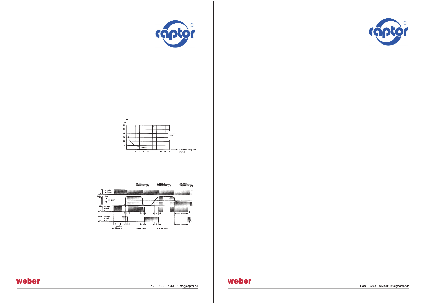
3.2 Switching delay
The time delay of the vent-captor is defined by the rate of change of flow
speed relative to the set-point. This time delay is not constant, the faster
the change, the shorter the
time delay.
Depending upon adjustment it
varies from approx. 3s to
more than 30s.
4.0 Set-point adjustment
For general applications,
vent-captors are set at the
factory to a switching flow
rate of less than 4 m/s and are
therefore directly ready for operation without further adjustment.
4.1 Changing set-point:
Stable operating conditon reached 5 minutes after electrical connection.
4.11 Decrease sensitivity = higher set-point, turn pot. clockwise
4.12 Increase sensitivity = lower set-point, turn pot. counter clockwise
Installation and Adjustment Instruction
vent-captor 3202.12/.13 S300
Please read carefully: No liability can be accepted
for damage caused by improper use of the vent-captor.
Sensors GmbH · Strohdeich 32 · D-25377 Kollmar Tel.: +49 4128-591
Irrtum und technische Änderungen · vorbehalten Rev. AG / 06.05.20
The following instruction refer to the output .12 n.c.
4.2 With no air flow turn adjustment pot.counter clockwise until LED „red“
This position sets switch-point to zero flow. Slowly turn adjustment pot.
clockwise until LED „green“ = most sensitive setting. Further adjustment,
max. 18 turns results in least sensitivity.
Attention: 18 turn potentiometer without mechanical end point.
5.0 Monitoring air flow failure ( air flow below set-point)
5.1 After 5 minutes with no air flow, turn pot. counter clockwise until LED „red“
5.2 Turn on normal air flow, wait 3 minutes, adjust pot. clockwise (counting the
turns) until LED „green“
5.3 Turn back half the number of turns at 5.2 = optimum setting,
tr = tf (s. page 1/3 )
6.0 Monitoring lower flow limit
6.1 Reduce flow to the min. rate at which a signal is required.
6.2 After 5 minutes slowly turn pot. until LED „green“
6.3 Increase flow to normal rate, wait 3 minutes, if LED „red“, setting is correct.
6.4 If LED stays „green“ the flow rate difference is too small. In this case turn
slowly counter clockwise until LED „red“.
7.0 Monitoring upper flow limit
7.1 Increase flow to rate at which a signal is required.
7.2 Turn pot. clockwise until LED „green“
7.3 Wait 5 minutes turn pot. slowly counter clockwise until LED „red“
7.4 Decrease flow to normal rate. Wait 3 minutes, if LED „green“ setting is
correct.
7.5 If LED stays „red“ the flow rate difference is too small.
In this case turn pot. clockwise until LED „green“.


