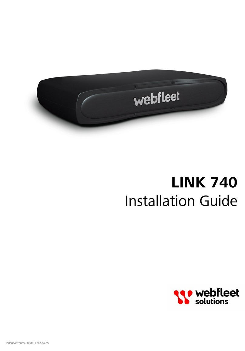
Webfleet LINK 240 User manual

LINK 240
Installation Guide
1596092388235 - Draft - 2021-04-20
LINK 240
Installation Guide
1596092388235 - Draft - 2021-04-20

Contents
Installation.............................................................................................................3
What’s in the box..................................................................................................................... 4
Read me first............................................................................................................................ 5
Congratulations................................................................................................................................5
Read t e Addendum and Safety notices..........................................................................................5
W at you need for t e installation..................................................................................................5
Safet first.................................................................................................................................6
Important safety notices and warnings............................................................................................6
Preparations.............................................................................................................................. 8
Activating t e LINK 240...................................................................................................................8
C oosing t e correct position..........................................................................................................8
Connecting the LINK 240..........................................................................................................9
Configuring the LINK 240 for fuel consumption reporting..................................................... 10
Diagnostics.............................................................................................................................. 12
Understanding your LINK 240........................................................................................................12
Troubles ooting............................................................................................................................. 13
Technical data.........................................................................................................................14
Addendum...........................................................................................................15
Important Safet Notices and Warnings................................................................................. 16
Prohibited uses....................................................................................................................... 17
CE mark and Radio Equipment Directive for LINK 240...........................................................17
FCC information for the user.................................................................................................. 17
Specific Absorption Rate (SAR) compliance............................................................................ 19
Environmental and Batter information..................................................................................19
Triman logo.............................................................................................................................20
Operating temperature........................................................................................................... 20
WEEE – e-waste disposal........................................................................................................ 20
How Webfleet Solutions uses our information..................................................................... 21
Exposure limits........................................................................................................................21
Technical Specifications.......................................................................................................... 21
Model numbers....................................................................................................................... 21
Responsible part in North America....................................................................................... 22
Customer support contact...................................................................................................... 22
This document........................................................................................................................ 22
WEBFLEET Telematics Service Platform.................................................................................. 22
Accessories supplied with this device..................................................................................... 22
Terms and conditions and Limited warrant .......................................................................... 22
Cop right notices.................................................................................................................... 22
Copyrig t (c) 2018 - Tcl/Tk - Regents of t e University of California, Sun Microsystems, Inc., Scriptics
Corporation, and ot er parties...................................................................................................... 22
RFC1321-based (RSA-free) MD5 library.......................................................................................... 23
Webfleet Solutions Limited Warrant ................................................................. 24
2

Installation
3

What’s in the box
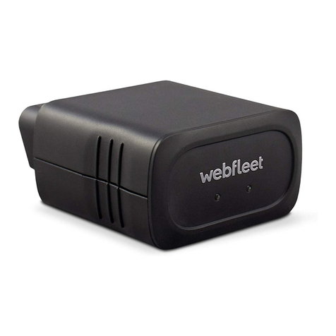
LINK 240
1. OBD-II connector.
2. Yellow LED - connection status indicator
3. Green LED - system status indicator
•Two QR-Code labels
•Installation booklet
4

Read me first
Congratulations
You ave c osen t e LINK 240, a core ardware component of t e WEBFLEET fleet management solution.
Wit WEBFLEET you are connected to your people out on t e road in a smart and easy way.
LINK 240 is a GNSS receiver and mobile network module in one unit, providing t e ve icle’s current posi-
tion.
You can use t e LINK 240 in ve icles equipped wit an OBD-II port.
Read the Addendum and Safet notices
IMPORTANT – BEFORE INSTALLING AND USING YOUR LINK DEVICE READ THE ADDENDUM AND THE
INSTRUCTIONS CONTAINED THEREIN! ALSO READ THE IMPORTANT SAFETY NOTICES AND WARNINGS IN-
CLUDED IN THIS DOCUMENT! READ THE INSTRUCTIONS IN THIS DOCUMENT THOROUGHLY!
What ou need for the installation
Note: To find t e compre ensive Installation Guide, please visit www.webfleet.com/support
Before starting t e installation of your LINK 240, read t e installation instructions and t e safety notices and
warnings carefully and make sure you ave t e following:
•T e Contract Confirmation letter including t e Activation Code.
•A device wit internet connection t at is able to scan QR codes, as t e LINK Toolkit app installed and
t e necessary LINK Tookit login credentials.
•T e QR code of t e LINK 240 (on t e device label or on t e additional QR code label).
•All parts contained in t e box.
•A place with a clear view of the sk w ere you can move your ve icle to c eck GNSS reception.
5

Safet first
Important safet notices and warnings
Important: Read t e following safety instructions carefully.
Webfleet Solutions accept no liability for damage t at results from disregarding t e safety instructions. T is
document is part of t e product. Keep it in a safe place. If you pass t e unit on to a new user, make sure
you give t em t is document as well.
Positioning
Position t e device in suc a way t at it doesn’t block or interfere wit your view of t e road, t e controls in
your ve icle, or t e rear-view mirrors and airbags.
Danger of explosion
Parts of t is product can cause sparks t at can lead to explosions. T is may endanger uman ealt and life.
Do not use t e unit in areas wit ig risk of explosion. W en using t is product in a ve icle fuelled by liq-
uefied gas, follow t e safety regulations of t e country in w ic t e ve icle is operated.
Damage caused through improper installation
T e installation and initial operation of t e unit must be performed by aut orised personnel only, for exam-
ple, a qualified radio dealer or an automotive electronics works op.
Risk of injur in case of accidents
Do not mount t e unit or accessories in t e inflation area of airbags or in t e impact area for t e ead or
knees. C oose an installation location t at will avoid interference wit displays, safety equipment and con-
trols.
Damage to the chassis
Make sure you do not drill into parts of t e c assis t at ave structural or security-related functions. T is is
because you cannot be certain t at t ey will function properly after modification.
Repair and replacement
Repairs must be carried out by aut orised and qualified personnel only. Never replace damaged parts of t e
unit yourself. Send t e defective unit to Webfleet Solutions for repair. Only t e qualified staff of Webfleet
Solutions are aut orised to repair or replace parts.
Damage to the device
S ort-circuits inside t e unit can be caused by contact wit water or ot er liquids. T e unit may be dam-
aged by contact wit water. Use and store t e unit in an area protected from water.
6

Use of this product is restricted in some areas
T is product contains a mobile network module w ic can interfere wit electrical devices suc as cardiac
pacemakers, earing aids and aviation equipment. Interference wit t ese devices may endanger t e ealt
or life of you or ot ers. If your device includes a mobile network module, do not use it near unprotected
electrical units or in areas w ere t e use of mobile telep ones is pro ibited, suc as ospitals and aircraft.
7

Preparations
Activating the LINK 240
You can use t e LINK Toolkit app w ic will guide you t roug t e activation process of your LINK 240 de-
vice.
Make sure you ave t e following:
•T e Contract Confirmation letter including t e Activation Code.
•A device wit internet connection t at is able to scan QR codes, as t e LINK Toolkit app installed and
t e necessary LINK Toolkit login credentials.
•T e QR code of t e LINK 240 t at you can find on t e device label or on t e addtional QR code label.
In addition to t e LINK Toolkit app you can use an online installation tool to activate t e LINK 240. To go
t ere please scan t e QR code of t e LINK 240 t at you can find on t e device label or on t e additional la-
bels provided wit t e device. If login credentials are needed for t e online activation tool, please contact
Webfleet Solutions or your fleet manager.
Note: If t e LINK 240 QR code cannot be scanned, t e LINK Toolkit app as well as t e online installation
tool also support t e activation of t e LINK 240 using t e device serial number and t e device activation key
(DAK), w ic you can also find on t e QR code labels.
Choosing the correct position
First you need to c oose t e correct position in w ic to install your LINK 240.
Take t e following into consideration:
•Do not expose t e LINK 240 to direct sunlig t and/or ig temperature for long periods to ensure prop-
er operation.
•To ensure GNSS reception using t e integrated GNSS receiver, t e top of t e device must not be ob-
structed by metal items.
•To ensure mobile network reception using t e integrated antenna, t e device must not be placed on or
surrounded by metal items suc as t e ve icle’s coac work closer t an 5 cm (2 inc es) and t e top side
must not be obstructed by metal items.
•If t e OBD-II connector of your ve icle does not provide enoug space to insert t e LINK 240, you can
use t e OBD-II extension cable from Webfleet Solutions.
•If t e OBD-II extension cable is used, make sure it is firmly fixed so it cannot interfere wit t e driver's
actions.
8

Connecting the LINK 240
Important: To connect or disconnect t e LINK 240, t e ve icle ignition must be off.
To connect your LINK 240 to t e ve icle and calibrate it do t e following.
1. Make sure t e ignition of t e ve icle is turned off.
2. Find t e OBD-II port in your ve icle.
Refer to t e manual of your ve icle. In many ve icles you can find t e OBD-II port in t e footwell (A),
close to t e fuse box (B), beneat t e das board (C), or in t e centre console (D).
3. Insert t e LINK 240 into t e OBD-II port.
Tip: If t e space surrounding t e OBD-II port in your ve icle does not allow t e LINK 240 to be insert-
ed, you can use t e OBD-II extension cable from Webfleet Solutions. If you use t e OBD-II extension
cable, make sure you ave firmly fixed it so it cannot drop off. Make sure t e cable does not interfere
wit t e driver's actions.
4. Start t e engine of your ve icle.
T e green LED of your LINK 240 is permanent on to s ow t e device is properly connected to t e ve i-
cle and t e engine is running.
5. Turn off t e ignition.
9

Configuring the LINK 240 for fuel
consumption reporting
Important: For fuel consumption reporting your must ave ECO subscription booked for your LINK 240 de-
vice.
You can configure your LINK 240 for fuel consumption reporting using WEBFLEET or t e LINK Toolkit app.
Configuration via WEBFLEET
1. Log in to WEBFLEET.
2. Click t e ve icles icon in t e main menu to s ow t e Ve icles view.
3. Select your ve icle from t e list.
T e ve icle details panel opens.
4. Click t e Details button.
5. Go to t e Device Configuration tab.
6. Click Edit.
7. Go to t e Fuel reporting section.
In t e fields for Engine size (cc) and Power (kW), enter t e size in cc and t e power in kW of t e en-
gine of your ve icle.
Important! Make sure you ave entered t e correct engine size and power, as t is information is t e
basis for t e calculation of t e fuel consumption of your ve icle.
8. Select if malfunctions detected by t e ve icle diagnostic system s ould be reported.
9. Click Save.
Configuration using the LINK Toolkit app
1. Download t e latest version of t e LINK Toolkit app and install it on your p one.
2. Open t e LINK Toolkit app.
3. Enter your user name and password and tap Login.
4. Select t e LINK 240 device type.
5. Scan t e QR-Code of your LINK 240.
T e LINK Toolkit app s ows t e status screen for t e selected LINK 240 device.
Important! Make sure t e LINK 240 device s ows t e status Activated.
6. Tap t e + button.
7. Select Configuration.
8. In t e field for Activation code, enter t e contract activation key.
9. Tap on t e c eck mark button to confirm.
T e Configuration view is s own.
10. In t e Fuel reporting section, enter t e power in kW and t e size in ccm of t e engine of your ve icle
in t e fields for Engine power (kW) and Engine size (in ccm).
10

11. Tap on Appl .
T e LINK Toolkit app confirms t e successful configuration.
11

Diagnostics
Understanding our LINK 240
You can monitor t e system operation of your LINK 240 by looking at t e green system LED and referring to
t e table below.
Important: T e LINK 240 device must be activated in WEBFLEET.
GREEN LED mode
OFF Unit is in standb mode or is not connected to power.
•Switc on ignition.
•C eck if t e device is properly connected to power.
OFF and short ON ever 3sec Ignition off (not detected).
Flashing No operating s stem and/or no application available or
application failed.
•Contact t e Webfleet Solutions support team at
www.webfleet.com/support.
Rapidl flashing (YELLOW LED is OFF) Reset to factor settings
ON and short OFF ever 3sec Ignition on. Application is running, device is not activat-
ed.
•Activate device.
ON Application is running, device is activated.
You can monitor t e connection of your LINK 240 to t e mobile network by looking at t e yellow connec-
tion LED and referring to t e table below.
YELLOW LED mode
OFF Not connected - No mobile network coverage.
•C eck if device is connected to power. Switc on ignition.
•Move t e ve icle as you may be in a mobile network
dead spot.
OFF and short ON ever 3sec Not connected - Correct mobile network operator not
avaialable.
•C eck contract for mobile network roaming support.
•Move t e ve icle as you may be in a mobile network
dead spot.
Flashing SIM not in place; SIM defective; Modem problem.
•In case of SIM modem issues, please contact t e Webfleet
Solutions Customer support at www.webfleet.com/sup-
port.
12

ON and short OFF ever 3sec Connecting.
•If for longer t an ten minutes, please contact t e
Webfleet Solutions support team at www.webfleet.com/
support.
ON Connected.
Troubleshooting
If your LINK 240 does not report trips to WEBFLEET properly anymore, t e device may need to be reset. For
t is please contact t e Webfleet Solutions Customer Support.
If you experience tec nical issues or ave frequently asked questions, please go to t e Customer Support
Portal on www.webfleet.com/support
13

Technical data
Dimensions 57 x 48 x27 mm / 2.24 x 1.89 x 1.06 inc
Weig t 56g / 1.98oz
Material Injection moulded plastic PC/ABS
Protection class IP 20
Supply voltage 12 V / 24 V (min. 9 V to max. 30 V)
Current / power con-
sumption (average val-
ues)
At 14V: typically <0.07A / <1W
At 28V: typically < 0.04A / < 1.1W
Standby typically : < 0.002A / < 0.03W
During data transmission:
14V < 0.17 A / <2.4W
28V < 0.11A / <3.1W
Fuse protection Operating voltage* 9 - 30 V to be fused wit max. 10A
* Internally fused wit 1A, fuse is not resettable or replaceable, fuse must be re-
placed by Webfleet Solutions only
Temperature Operation: -20 °C to +60 °C / -4 °F to +140 °F
Storage: -20 °C to +60 °C / -4 °F to +140 °F
Mobile networks Integrated mobile network module wit LTE-M and GPRS tec nology
GSM: 900 MHz; 1800 MHz
LTE Bands: 2 (1900MHz); 3 (1800MHz); 4 (1700MHz); 8 (900MHz); 12
(700MHz); 13 (700MHz); 20 (800 MHz); 28 (700MHz)
SRD frequency SRD frequency: 2400 MHz
GNSS Integrated GNSS antenna and GNSS receiver
Rec argeable battery As battery a Li-Ion battery wit 250mA is used for operational use
OBD protocols supported ISO15765 (CAN) on Pins 6/14, ISO9141
ISO14230 (K-Line) on Pins 7/15 and Pin 12
HS-CAN on Pins 1/9, 3/8 and 3/11
14

Addendum
15

Important Safet Notices and Warnings
Global Positioning S stem (GPS) and Global Navigation Satellite S stem (GLONASS)
T e Global Positioning System (GPS) and Global Navigation Satellite System (GLONASS) systems are satel-
lite-based systems t at provide location and timing information around t e globe. GPS is operated and con-
trolled by t e Government of t e United States of America, w ic is solely responsible for its availability and
accuracy. GLONASS is operated and controlled by t e Government of Russia, w ic is solely responsible for
its availability and accuracy. C anges in GPS or GLONASS availability and accuracy, or in environmental con-
ditions, may impact t e operation of t is device. Webfleet Solutions disclaims any liability for t e availability
and accuracy of GPS or GLONASS.
Safet messages
Important! Read before use!
Deat or serious injury could result from failure or partial failure to follow t ese warnings and instructions.
Failure to properly set up, use, and care for t is device can increase t e risk of serious injury or deat , or
damage to t e device.
Use with care warning
It is your responsibility to use best judgement, due care and attention w en using t is device. Don't allow
interaction wit t is device to distract you w ile driving. You are responsible for observing laws t at limit or
pro ibit t e use of mobile p ones or ot er electronic devices, for example, t e requirement to use ands-
free options for making calls w en driving. Alwa s obe applicable laws and road signs, especiall
those relating to our vehicle’s dimensions, weight and pa load t pe. Webfleet Solutions does not
guarantee t e error-free operation of t is device nor t e accuracy of route suggestions provided and s all
not be liable for any penalties arising from your failure to comply wit applicable laws and regulations.
Proper mounting
Do not mount t e device in a way t at may obstruct your view of t e road or your ability to control t e
ve icle. Do not place t e device in an area t at may obstruct t e deployment of an airbag or of any ot er
safety feature of your ve icle.
Pacemakers
Pacemaker manufacturers recommend t at a minimum of 15 cm / 6 inc es be maintained between a and-
eld wireless device and a pacemaker to avoid potential interference wit t e pacemaker. T ese recommen-
dations are consistent wit independent researc and recommendations by Wireless Tec nology Researc .
Guidelines for people wit pacemakers:
•You s ould ALWAYS keep t e device more t an 15 cm / 6 inc es from your pacemaker.
•You s ould not carry t e device in a breast pocket.
16

Other medical devices
Please consult your p ysician or t e manufacturer of t e medical device, to determine if t e operation of
your wireless product may interfere wit t e medical device.
Device care
•It is important to take care of your device:
•Do not open t e casing of your device under any circumstances. Doing so may be dangerous and will
invalidate t e warranty.
Prohibited uses
Aircraft and hospitals
Use of devices wit an antenna is pro ibited on most aircraft, in many ospitals and in many ot er loca-
tions. T is device must not be used in t ese environments.
CE mark and Radio Equipment Directive for LINK 240
T is device can be used in all EU Member States. Hereby, Webfleet Solutions declares t at t e radio equip-
ment type telematics black box is in compliance wit Directive 2014/53/EU. T e full text of t e EU decla-
ration of conformity is available at t e following internet address: ttps://www.webfleet.com/webfleet/le-
gal/doc/
T e frequency bands in w ic t is device operates are:
•GSM: 900 MHz; 1800 MHz
•LTE Bands: 2 (1900MHz); 3 (1800MHz); 4 (1700MHz); 8 (900MHz); 12 (700MHz); 13 (700MHz); 20 (800
MHz); 28 (700MHz)
•SRD frequency: 2400 MHz
And t e maximum radio frequency power wit in t ese bands as to be:
•GSM: 2W, 33 dBm for 900MHz, 1W, 30 dBm for 1800 MHz,
•LTE: 0,1W, 20dBM for all Bands
•SRD frequency: 2.5 mW, 4dBm
FCC information for the user
THE DEVICE COMPLIES WITH PART 15 OF THE FCC RULES
17

Federal Communications Commission (FCC) Statement
T is equipment radiates radio frequency energy and if not used properly - t at is, in strict accordance wit
t e instructions in t is manual - may cause interference to radio communications and television reception.
Operation is subject to t e following two conditions: (1) t is device may not cause armful interference and
(2) t is device must accept any interference, including interference t at may cause undesired operation of
t e device.
T is device as been tested and found to comply wit t e limits for a Class B digital device, pursuant to part
15 of t e FCC rules. T ese limits are designed to provide reasonable protection against armful interference
in a residential installation. T is equipment generates, uses and can radiate radio frequency energy and, if
not installed and used in accordance wit t e instructions, may cause armful interference to radio commu-
nications. However, t ere is no guarantee t at interference will not occur in a particular installation. If t is
equipment does cause armful interference to radio or television reception, w ic can be determined by
turning t e equipment off and on, t e user is encouraged to try to correct t e interference by one or more
of t e following measures:
•Reorient or relocate t e receiving antenna.
•Increase t e separation between t e equipment and receiver.
•Connect t e equipment into an outlet on a circuit different from t at to w ic t e receiver is connected.
•Consult t e dealer or an experienced radio/TV tec nician for elp.
C anges or modifications not expressly approved by t e party responsible for compliance could void t e
user's aut ority to operate t e equipment.
Important
T is equipment was tested for FCC compliance under conditions t at included t e use of s ielded cables
and connectors between it and t e perip erals. It is important t at you use s ielded cable and connectors
to reduce t e possibility of causing radio and television interference. S ielded cables, suitable for t e prod-
uct range, can be obtained from an aut orized dealer. If t e user modifies t e equipment or its perip er-
als in any way, and t ese modifications are not approved by Webfleet Solutions, t e FCC may wit draw t e
user’s rig t to operate t e equipment. For customers in t e USA, t e following booklet prepared by t e Fed-
eral Communications Commission may be of elp: "How to Identify and Resolve Radio-TV Interference Prob-
lems". T is booklet is available from t e US Government Printing Office, Was ington, DC 20402. Stock No
004-000-00345-4.
FCC ID: 2AGPAL0240
FCC RF Radiation Exposure Statement
T e transmitters wit in t is device must not be co-located or operating in conjunction wit any ot er anten-
na or transmitter.
FCC Countr Code Selection
T e Country Code Selection feature is disabled for products marketed in t e US or Canada. Per FCC regula-
tions, all Wi-Fi products marketed in US must be fixed to US operation c annels only.
Location of FCC ID on our device
T e FCC ID can be found on t e label attac ed to t e bottom side of your device.
18

Specific Absorption Rate (SAR) compliance
THIS WIRELESS DEVICE MODEL MEETS GOVERNMENT REQUIREMENTS FOR EXPOSURE TO RADIO WAVES
WHEN USED AS DIRECTED IN THIS SECTION
T is device is a radio transmitter and receiver. It is designed and manufactured not to exceed t e emission
limits for exposure to radio frequency (RF) energy set by t e Council of t e European Union, Innovation
Science and Economic Development Canada (ISED) and t e Federal Communications Commission of t e U.S.
Government. T ese limits are part of compre ensive guidelines and establis permitted levels of RF energy
for t e general population.
T e SAR limit set by t e FCC/ISED is 1.6W/kg averaged over 1 gram of tissue for t e body (4.0 W/kg aver-
aged over 10 grams of tissue for t e extremities - ands, wrists, ankles and feet). T e SAR limit recommend-
ed by T e Council of t e European Union is 2.0W/kg averaged over 10 grams of tissue for t e body (4.0 W/
kg averaged over 10 grams of tissue for t e extremities - ands, wrists, ankles and feet). Tests for SAR are
conducted using standard operating positions specified by t e FCC/ISED/EU council wit t e device transmit-
ting at its ig est certified power level in all tested frequency bands.
Before a wireless device model is available for sale to t e public, it must be tested and certified to t e FCC,
ISED, and T e Council of t e European Union t at it does not exceed t e limit establis ed by t e govern-
ment-adopted requirement for safe exposure under t e recommendations of t e International Commis-
sion on Non-Ionizing Radiation Protection (ICNIRP). T e tests are performed in positions and locations as re-
quired by t e FCC, ISED, and T e Council of t e European Union for eac model.
To maintain compliance wit FCC, ISED, and EU RF exposure guidelines, w en you carry a Webfleet Solu-
tions device wit an integrated mobile data module keep t e device at least 20cm (8 inc es) from your body
w en t e device is transmitting. If you use an accessory not supplied by Webfleet Solutions w en you car-
ry t e device, verify t at t e accessory does not contain metal and keep t e device at least 20cm (8 inc es)
from your body w en t e device is transmitting.
Environmental and Batter information
Your device
Do not disassemble, crus , bend, deform, puncture, or s red your device. Do not use it in a umid, wet and/
or corrosive environment. Do not put, store or leave t e device in a ig temperature location, in direct sun-
lig t, in or near a eat source, in a microwave oven or in a pressurised container, and do not expose it to
temperatures over 140°F / 60°C or below -20 °C (-4 °F).
Long period storage: -20 °C to +60 °C / -4 °F to +140 °F
Avoid dropping t e device. If t e device is dropped and you suspect damage, please contact customer sup-
port. Use t e device only wit t e c argers, mounts or USB cables provided. For Webfleet Solutions ap-
proved replacements, go to www.webfleet.com.
Device batter (Non-replaceable)
T is product contains a rec argeable lit ium ion battery t at is not replaceable.
Do not modify or re-manufacture t e battery. Do not attempt to insert foreign objects into t e battery, or
immerse or expose to water or ot er liquids. Do not expose t e battery to fire, explosion or ot er azard.
Do not s ort circuit a battery or allow metallic conductive objects to contact battery terminals.
Do not attempt to replace t e battery yourself unless t e user manual clearly indicates t at t e battery is
user replaceable.
User replaceable batteries must only be used in systems for w ic t ey are specified.
19

Caution: Risk of explosion if t e battery is replaced by an incorrect type.
Do not remove or attempt to remove t e non-user-replaceable battery and contact a qualified professional
in case you wis to remove it.
Failure to follow t ese guidelines may cause t e battery to leak acid, become ot, explode or ignite and
cause injury and/or damage. Do not attempt to pierce, open or disassemble t e battery. If t e battery leaks
and you come into contact wit t e leaked fluids, rinse t oroug ly wit water and seek medical attention
immediately.
Batter waste disposal
THE BATTERY CONTAINED IN THE PRODUCT MUST BE RECYCLED OR DISPOSED OF PROPERLY ACCORDING
TO THE LOCAL LAWS AND REGULATIONS AND ALWAYS KEPT SEPARATE FROM HOUSEHOLD WASTE. BY
DOING THIS YOU WILL HELP CONSERVE THE ENVIRONMENT.
Triman logo
Operating temperature
T is device will remain fully operational wit in t e following temperature range:
LINK 210: -20 °C to +60 °C / -4 °F to +140 °F
Prolonged exposure to ig er or lower temperatures can cause damage to your device and is t erefore ad-
vised against.
WEEE – e-waste disposal
As required by Directive 2012/19/EU (WEEE) t is product is marked wit t e crossed-out w eeled-bin sym-
bol on its body and/or packaging. T is product s all not be treated as ouse old waste or be disposed of as
unsorted municipal waste. To elp protect t e environment, please dispose of t is product by returning it to
t e point of sale or bringing it to your local municipal collection point for recycling
20
Table of contents
Other Webfleet Automobile Accessories manuals
Popular Automobile Accessories manuals by other brands

Steren
Steren POD-090 user manual

Safe Fleet
Safe Fleet Prime Design PBR 6000 Assembly instructions

ATS
ATS L6108A Fitting instructions

Direction Plus
Direction Plus Ford Ranger PX Direction Plus ProVent 150 installation guide

Westfalia
Westfalia 316 145 manual

AMP Research
AMP Research PowerStep XTreme 78122-01A installation guide